Ghani Lawal
-
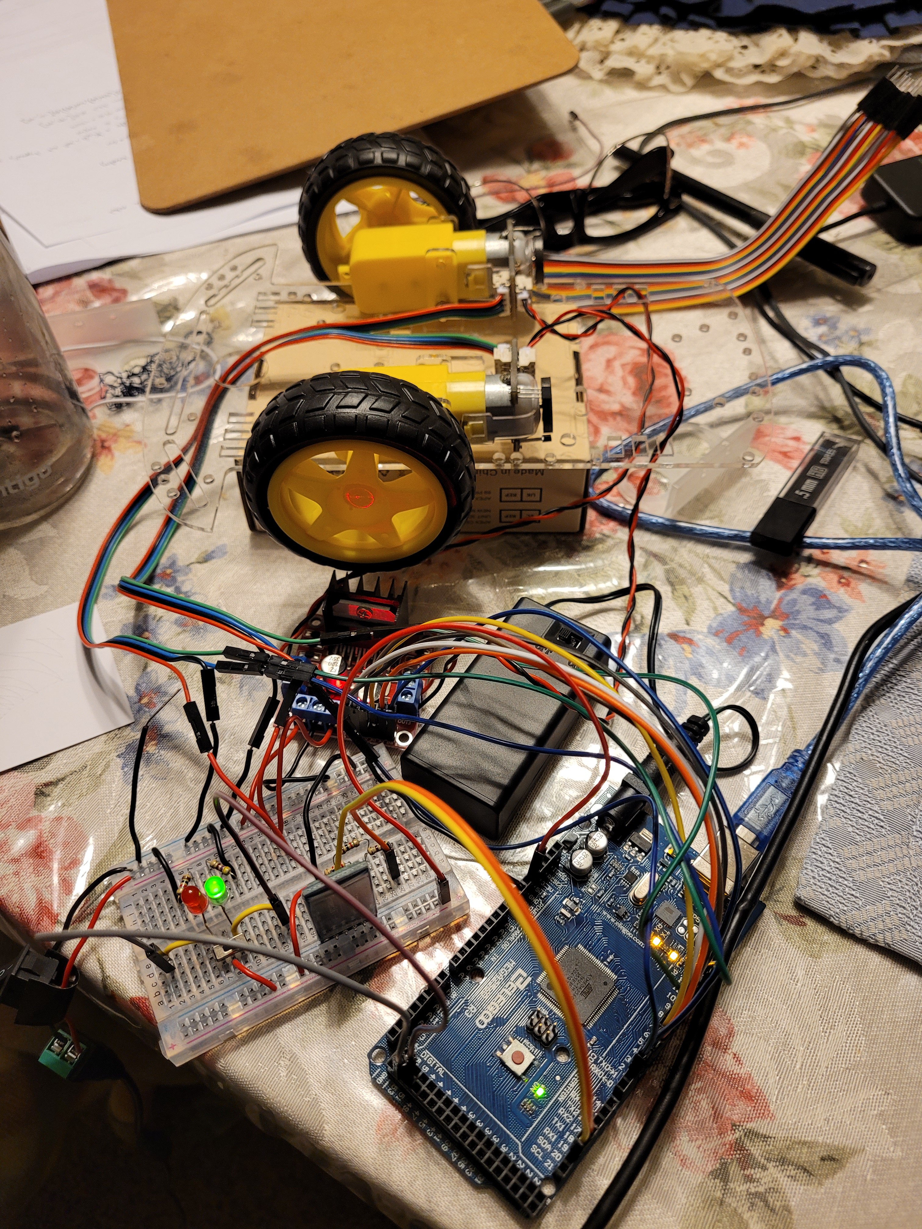
Project Complete
03/17/2022 at 23:00 • 0 commentsAdded images of the current robot build and associated app interface. Uploaded video of me controlling the robot using an app created using MIT App Inventor. The project is now complete!!
-
Excel Files
03/17/2022 at 05:14 • 0 commentsUploaded excel files showing results of step response test, the relationship between the PWM signal sent to the motor vs the supply voltage value and resulting motor speed. Also included cost breakdown of the project i.e. Bill of Materials
-
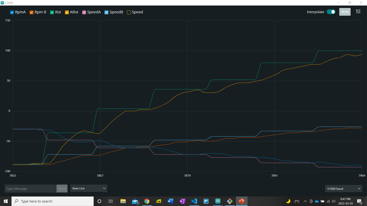
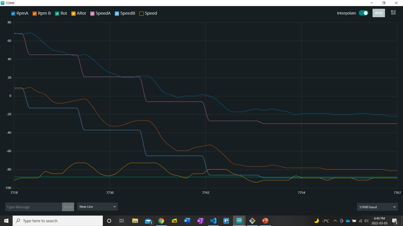
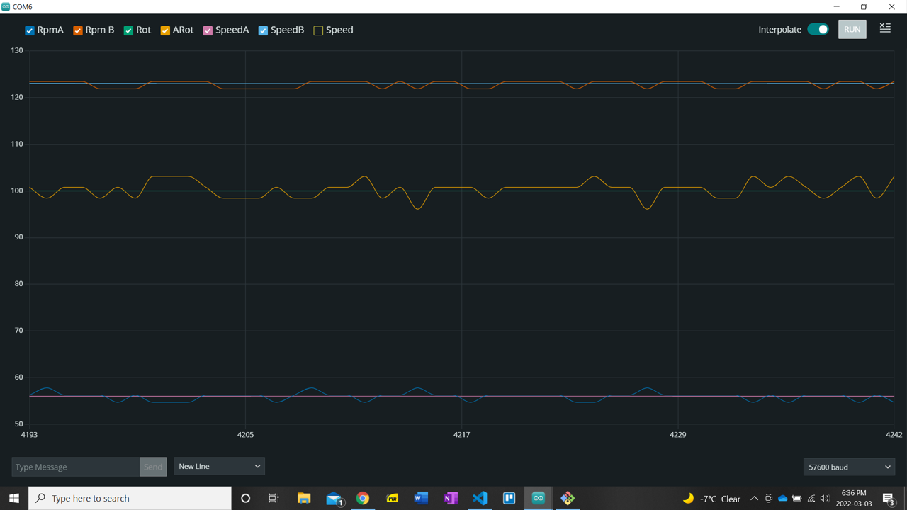
Remote Control of Linear and Angular Velocity
03/03/2022 at 23:52 • 0 commentsCan now control the linear and angular velocity of the robot using the phone app via Bluetooth. In order for the velocity commands to be parsed properly I had to increase app time interval to 100 milliseconds to ensure stable connection and switch which command, linear or angular, was sent at every time interval using a flag.
![]()
![]()
![]()
![]()
-
Control Switch
02/28/2022 at 05:01 • 0 commentsUsing a Baud rate of 9600 is no longer feasible. Kp and Ki values that gave the motor stable operation (6 and 3) are now causing sustained oscillations for certain step inputs.
I was able to change the baud rate of the HC-06 Bluetooth module to 19200, will be using the value to communicate over Bluetooth and USB from now on. May test how increasing baud rate affects stability of the system. Also adjusted to PID constants to give "smoother response".
I have also implemented a switch that will allow me to switch control of the robot from the phone app via Bluetooth and using a Serial port via Bluetooth or serial. For the phone case I am still printing the speed values to the phone and pc so that I can graph the values on the pc.
![]()
-
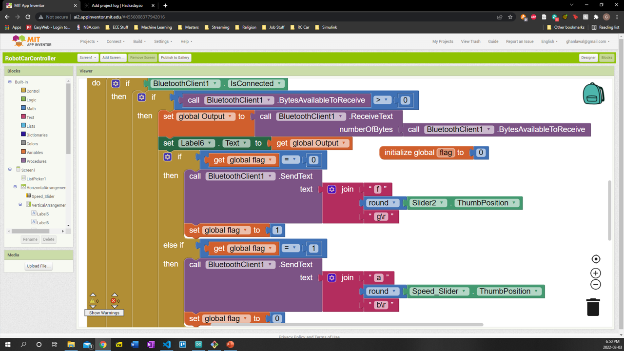
Speed control via Bluetooth and Phone App
02/26/2022 at 22:45 • 0 commentsOriginally intended to send speed command every time the position on the slider changed. This was giving me wildly inaccurate values. According to
as the slider moves "updates occur very rapidly; this has the potential to overflow the Arduino input buffer.
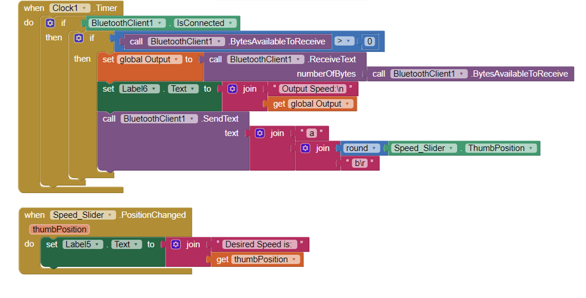
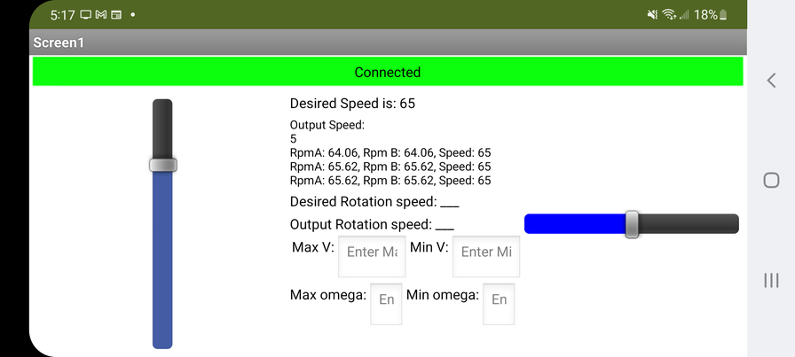
Therefore I decided to use the Clock.timer block to send the speed command at the clock interval, which was either 100 or 50 ms at the time. The data sent was still 'slightly off'; so I rounded the position of the slider to the closest integer and prepended the value with "\r". This worked... for the most part, but pretty often the app would send only a subset of the desired speed to the Arduino. E.g. say Speed = "123" the Arduino would only receive "12" or "23". To solve this last problem I created a added parity bytes to the speed command. "a" was appended to the desired speed and "b" was prepended to the desired speed i.e. Speed = "a123b". If the first byte isn't "a" and the last byte isn't "b" then the desired speed value of the Arduino would not be changed.
![]()
***Now have full, stable and consistent control of the speed of the motors using the app created using MIT app Inventor via Bluetooth,
![]()
-
Communication and Control
02/25/2022 at 23:50 • 0 commentsControl code works over USB at any given baud rate.
Only baud rate of 9600 works over Bluetooth when connected to phone app or computer. There is probably a setting to change the baud rate of the module but that is not priority right now.
At a baud rate of 9600 there were sustained oscillations in both motor when making large downwards steps like say going from 100 rpm to 10 rpm when the Arduino is connected to the computer over USB. I lowered Kp from 8 to 6 and Ki from 5 to 3. Takes a while to reach desired value, but no oscillations.
Will address above issues once phone app is working.
-
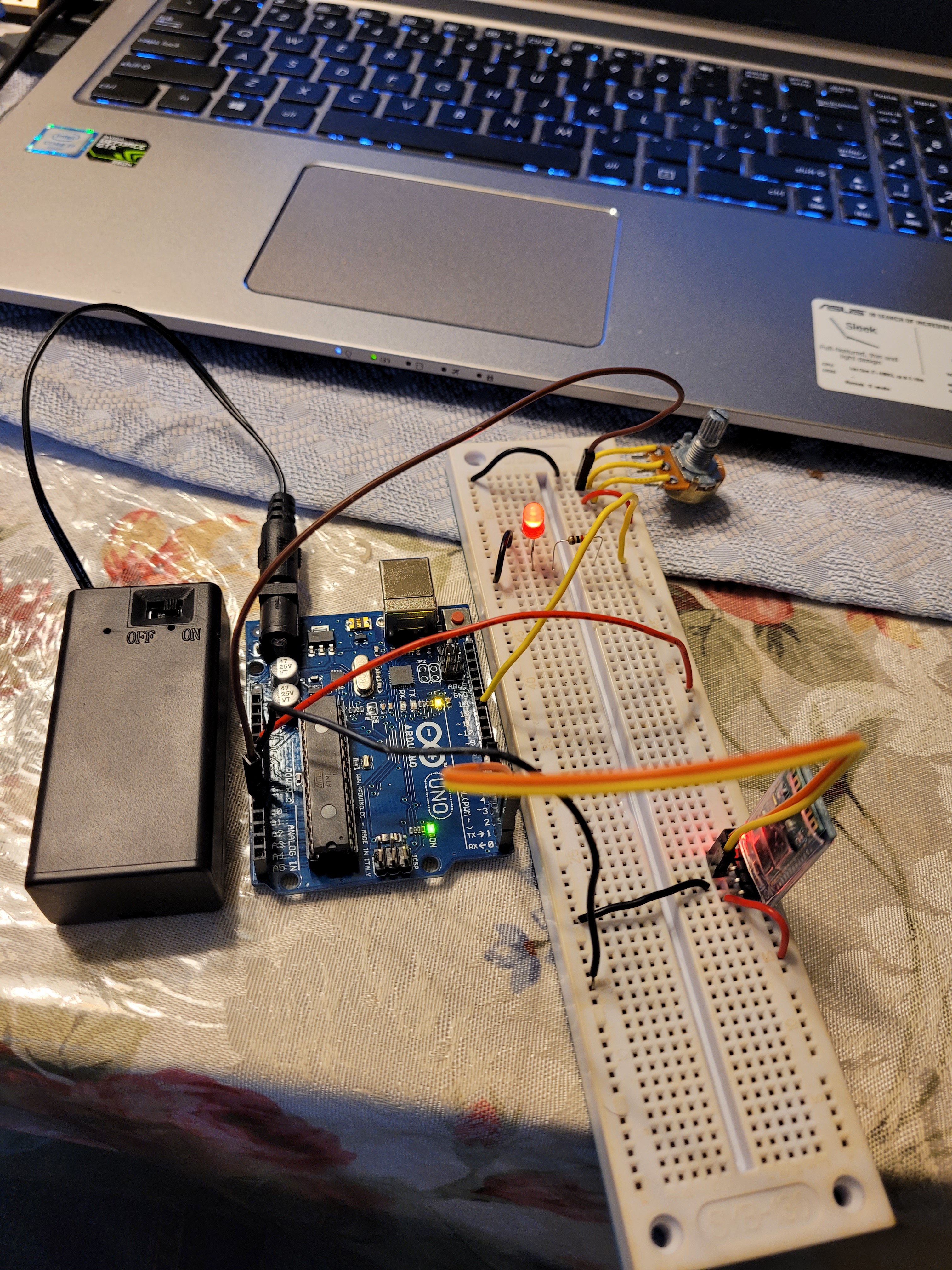
Bluetooth Module Test
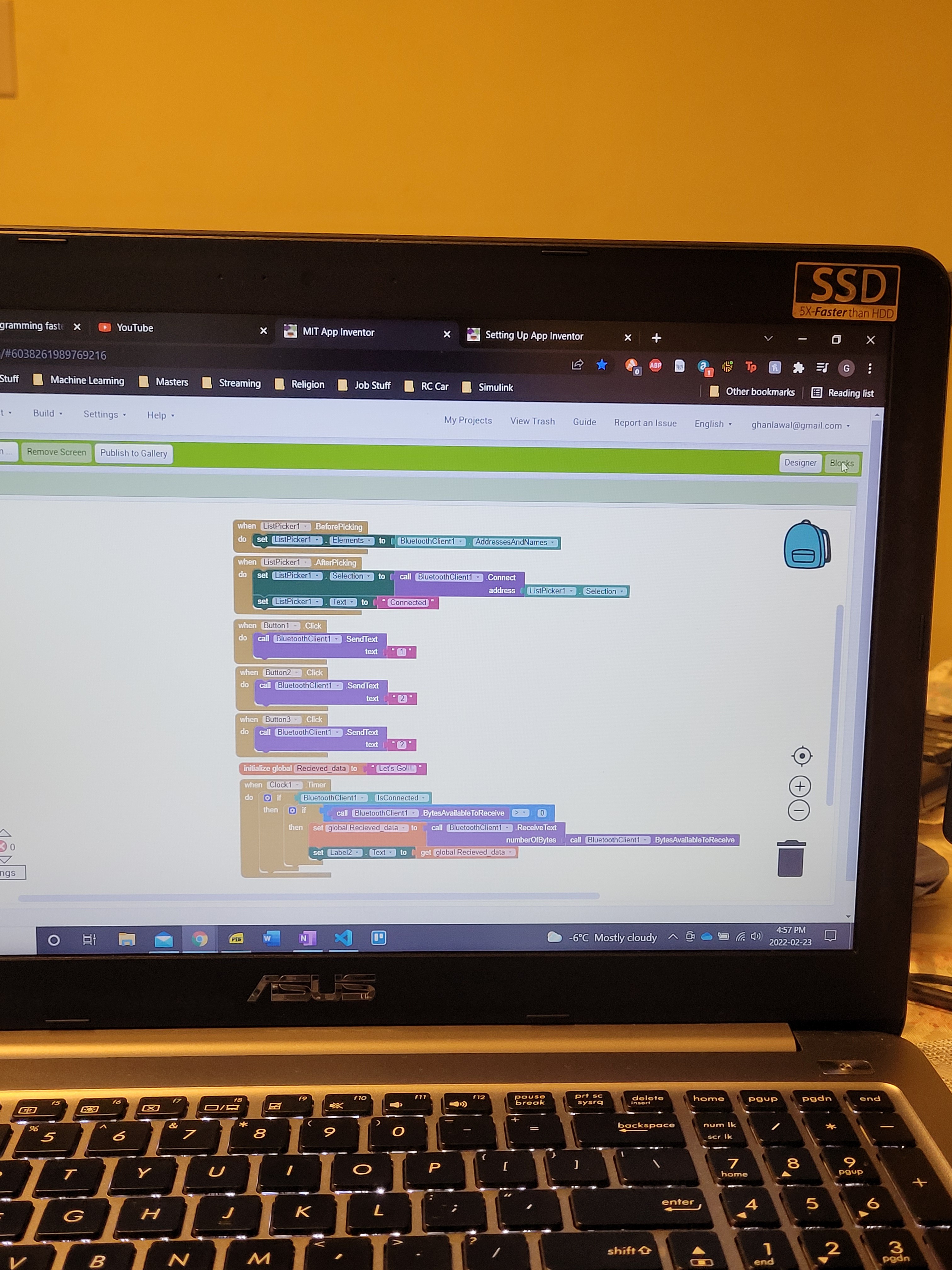
02/23/2022 at 22:01 • 0 commentsUsed an app created from MIT App Inventor to connect to and control an Arduino via Bluetooth.
![]()
![]()
![]()
Used a variation of the classic "Blink LED" sketch to test functionality. Test was successful.
-
Simulink Communication
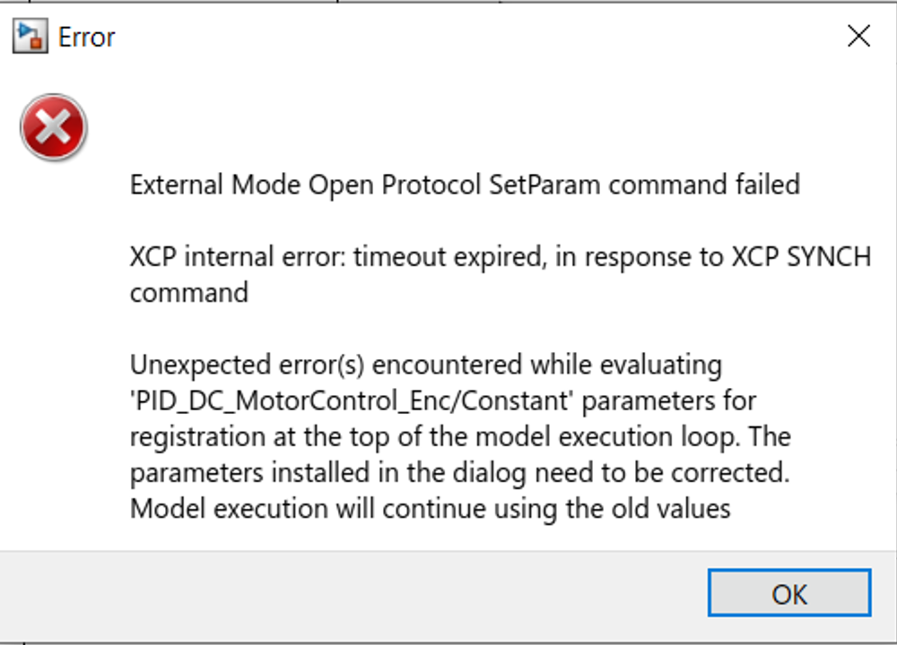
02/22/2022 at 21:04 • 0 commentsThe tachometer block only uses one encoder/interrupt pin, therefore it can't acquire the direction of the wheel. The fastest way to slow down the wheel from say 120 rpm to 0 rpm in the CW direction is to command the motor to spin as fast as possible in the CCW direction. This is how my code works in C/C++ and the motor exhibits an underdamped/critically damped response. However because I can't acquire direction information with the tachometer the system has to command the motor to spin slower, leading to an overdamped response. In order to accurately model and test the dynamics of the motor and control system I tried using the two pin Encoder Arduino Block.
Unfortunately when using the encoder block it was discovered that Simulink can't maintain communication with the Arduino and change values of the parameters at the same time.
![]()
This coupled with the fact that Interrupts only work in "External IO Mode" make testing the control system in Simulink an arduous task. Also, when I tested the systems response to a sinusoidal input it lost connection after 30 seconds.
******Ordinarily I would not bother using Simulink to complete this project. It hasn't added any value in terms of getting better control parameters or acquiring a deeper understanding of the motor dynamics. However a lot of recruiters in the field I want to join want new hires with experience turning Simulink code into C/C++ code and implementing it onto a system
-
Reading Encoders via Simulink
02/18/2022 at 23:12 • 0 commentsTachometer and Encoder Simulink blocks (anything the requires an interrupt) only works in External Mode (Monitor and Tune), the can't be used in Connected I/O Mode
When using a pulses/rotation = 1920 for when the trigger is set to CHANGE, there appears to be aliasing in the calculated speed of the motor when the PWM command rises above 120. i.e PWM=[0:120] -> RPM = [0:100], PWM =[120:200] -> RPM=[0:50]
Therefore, when using Tachometer the trigger will be set to RISING and the pulses/rotation = 960.
Tried using the Encoder block that requires ports of quadrature encoder to be connected to both be connected to interrupt pins. Appears to work.
***It seems that Simulink is unable to maintain communication with the Arduino when it is receiving messages from more than 2 interrupt pins at once.
-
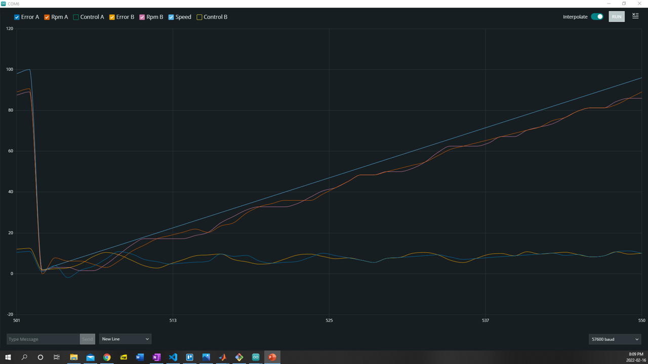
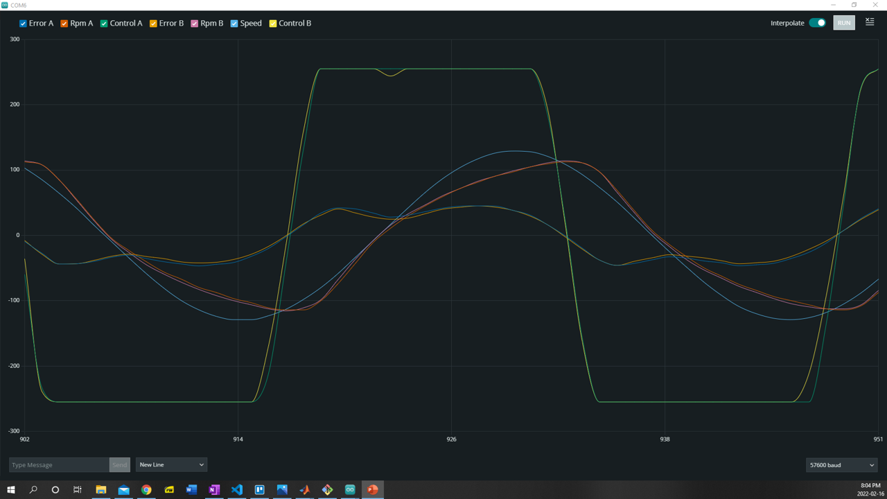
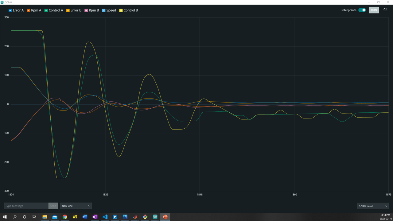
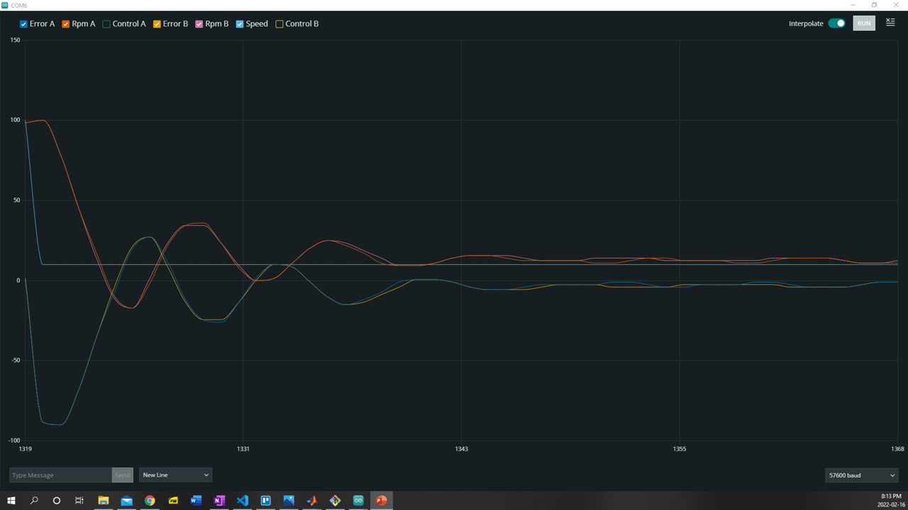
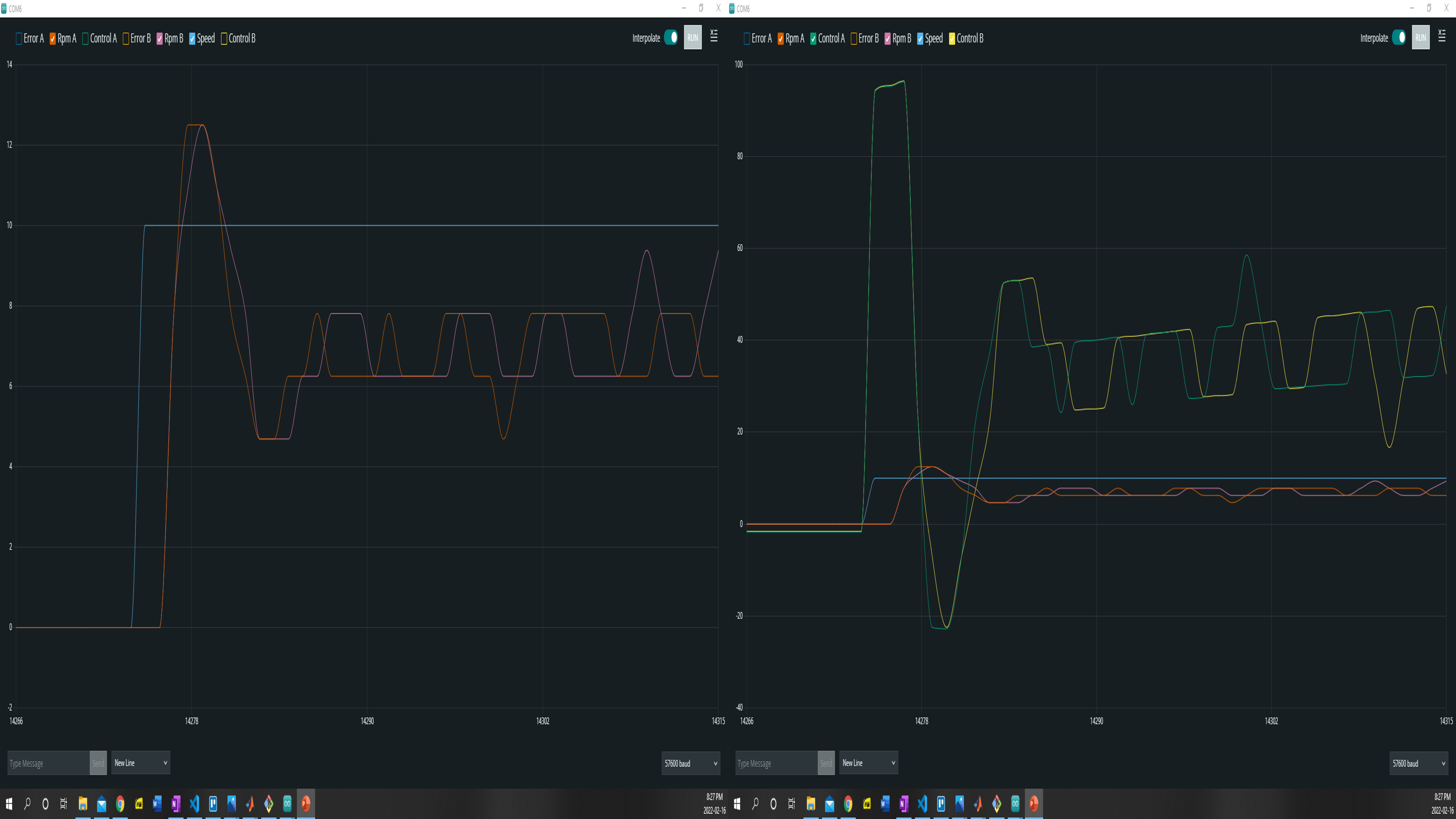
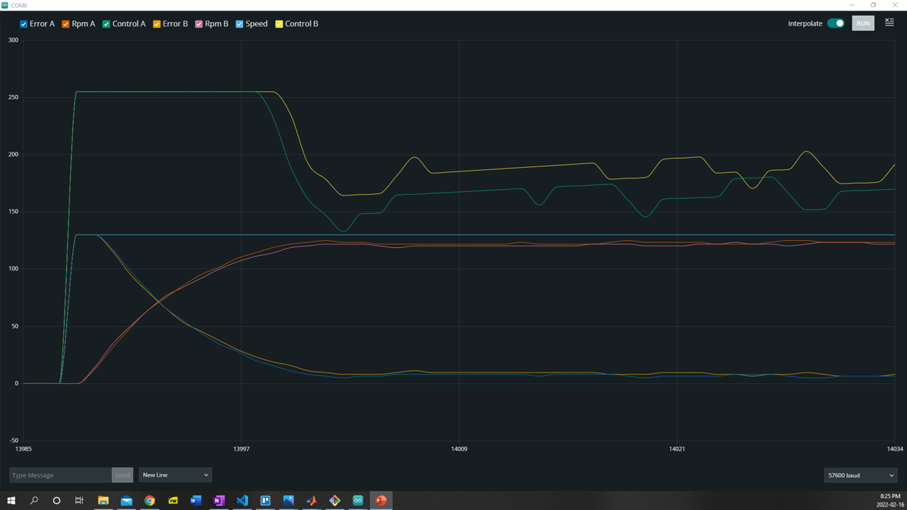
Dynamic Response
02/17/2022 at 02:06 • 0 commentsCompleted surface level investigation into dynamic response of the motors.
For step response to speeds up to 100 the system appears underdamped. Motor A consistently settles to within 90% of its final value quicker than Motor B. Motor A usually has a settling time of less than 0.4 seconds. Motor B usually has a settling time of within 0.8 seconds, thought it can deviate from the desired value 100-300 ms latter, but is definitely is settled within 1.5 seconds of the step input
For step responses to speeds from 110-130 rpm the system appears critically damped. Motor A settles to within 90% of its final value within 0.24 seconds. Motor B settles to within 90% of its final value within 0.26 seconds.
When stepping down by more than 15 rpm from any speed the system appears underdamped. Stepping down by less than 10 rpm system appears critically damped.
Kp= 8.5, Ki = 5, Kd = 0.02; SampleTime = 20 milliseconds. Saved plots for ramp, step and sinusoidal responses
![]()
![]()
![]()
![]()
![]()
![]()
Remote Control Differential Drive Robot Car
A remote control differential drive robot car where the linear & angular velocities of the are controlled using a PID control system.