-
1Step 1
The JeremFuge has several parts that can be built independently : the electronic part (involving welds and electrical connecting), the computer programming (Arduino) and the development of the box.
It is recommended to start with the electronic part or computer programming because they require most of the work and the structure of the box relies on your connections.
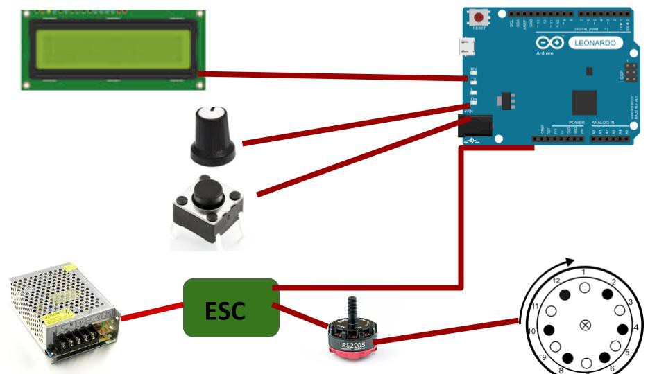
- Electronic part : Here is a pattern of the electrical connecting :
![]()
- Electronic part : Here is a pattern of the electrical connecting :
-
2Step 2
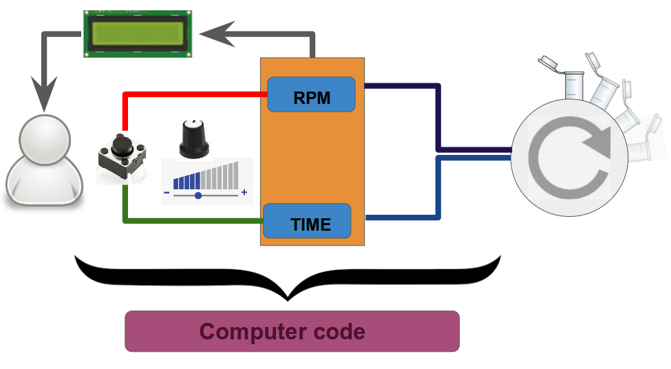
- Arduino program: User choices the RPM and the TIME thanks to two buttons, the first to select between RPM and TIME, the second one to increase or decrease the value. These values are printed on the LCD screen so the user can control it at any time. Then, once he has set correctly his values, he can launch the centrifuge.
![]()
- Arduino program: User choices the RPM and the TIME thanks to two buttons, the first to select between RPM and TIME, the second one to increase or decrease the value. These values are printed on the LCD screen so the user can control it at any time. Then, once he has set correctly his values, he can launch the centrifuge.
-
3Step 3
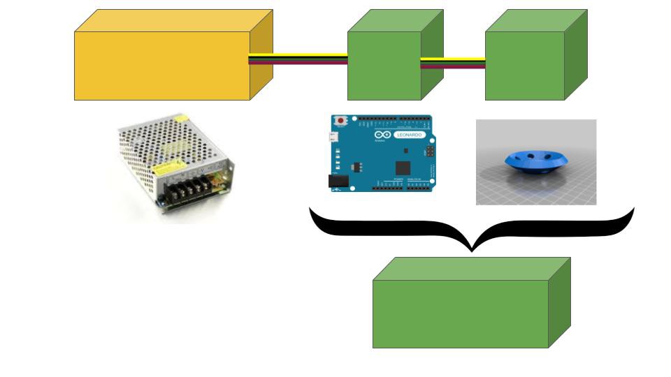
- Box preparation : The box must contain all the components and allow a modularity. It also must take into account the power supply warming and the vibration of the centrifuge.
The files for 3D printing the tube holder are available in the link in the Details section.
The files for laser cutting the boxes are in the Files section.
![]()
-
4Step 4
Here below are all the connections for the JeremFuge. We describe them cable per cable with each time the beginning and the end of the cable.
The breadboard is welded on the Arduino Uno.
Connections Breadboard : Arduino Uno
A : Digital
A2 to A7 : 2 to 7 (3, 5 and 6 are ~)
A9 to A14 : 8 to 13 (9 to 11 are ~)
T : Analog
T3 : A0
T8 : Gnd
T10 : 5V
Cables
Each pair represents a cable (or resistance) with beginning and end (if resistance, in the sense of the resistance)
Code
[letter] + [integer] = position on breadboard
LCD + [string] = position on LCD
R/M/L + [string] = right, middle or left of component (when holding it up and facing all the cables)
+/Gnd = positive or ground
Button1 = settings
Button2 = start
Resistance1 = 473K ohm
Resistance2 = 11K ohm
Are welded together : X6 to X18, H1 to O1, J6 to L6, H5 to H7, N6 and N7, A1 and A2
Connections
A2 – LCDD7
A3 – LCDD6
A4 – LCDD5
A5 - LCDD4
A6 – H6
A7 – K6
A9 – Button1
A10 – ESC+
A12 – LCDE
A13 – LCDRS
A14 – Button2
J1 – LCDVSS
H6 – RRotaryEncoder
K1 – LCDK
K6 – MRotaryEncoder
L1 – LPotentiometer
M1 – ESCGnd
M1 – LCDRW
N6 – Button2Gnd
O1 – T8
S01 – Button1Gnd
T05 – MPotentiometer
X7 – LCDA
X8 – Button1+
X10 – T10
X13 – Button2+
X14 – RPotentiometer
X16 – LRotaryEncoder
X17 – LCDVDD
MPotentiometer – LCDV0
H6 – H1 (Resistance1)
K6 – I1 (Resistance1)
N1 – N6 (Resistance1)
S1 – 01 (Resistance2)
JeremFuge (a.k.a. LC-LE:fuge)
A DIY and cheap, yet efficient, modular and user-friendly centrifuge. Building a genuine lab tool for less than 50€.
 Leon FAURE


Discussions
Become a Hackaday.io Member
Create an account to leave a comment. Already have an account? Log In.