 Swaleh Owais
-
1Find a 3D Printer to Modify
![]()
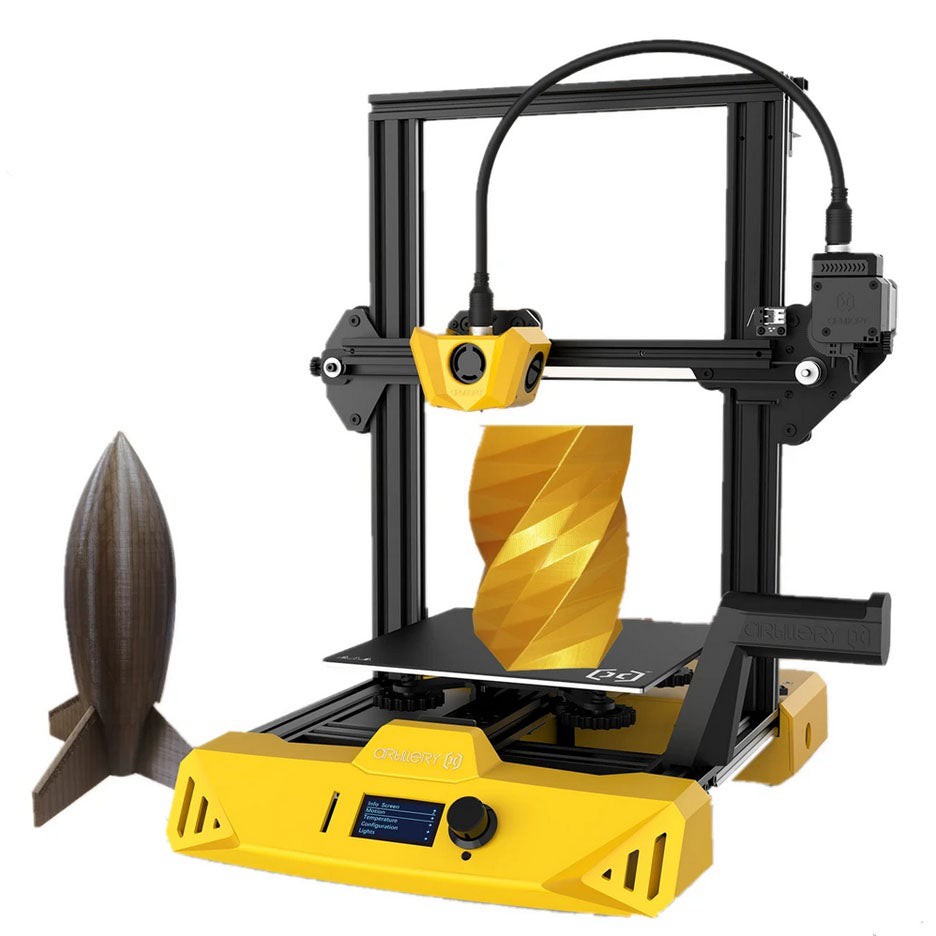
[Figure 1: Artillery3D Hornet - The 3D Printer I will be Modifying]
![]()
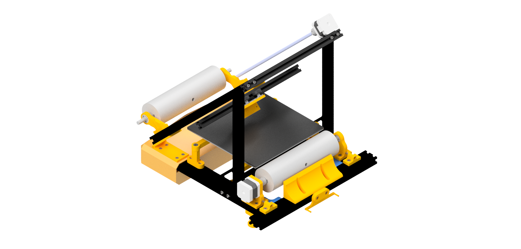
[Figure 2: CAD Render of Artillery3D Hornet after Conversion is Complete]
We could build our 3D printer entirely from scratch, but that would be a lot of work and a total PITA. Instead, it is much easy to take an old shitty 3D printer and reincarnate it as a s3xy conveyor belt 3D printer. I am assuming anyone who is interested in building a conveyor belt 3D on Hackaday already has some 3D printer parts lying around 💪
You can turn almost desktop FDM 3D printer into a conveyor belt 3D printer. In this tutorial, I will be modifying an Artillery3D Hornet 3D Printer. I am modifying this 3D printer because Artillery3D gave me several of them for free. Thanks Arillery3D!
I repeat, you can use pretty much any hobby FDM 3D printer for this project. However, all of 3D models I designed are specifically meant for the Artillery3D Hornet. The easiest way to following this tutorial is by using that exact 3D printer. However however, I have included the CAD for all of these 3D models as well. So you can modify the parts to match other 3D printers (i.e. TronyXY, Ender3, Prusa, etc).
If you do modify the CAD, please let me know! I would love to add your models to the repo (with proper credit of course:)) so that more people can build conveyor belt 3D printers.
-
2Print out the Parts
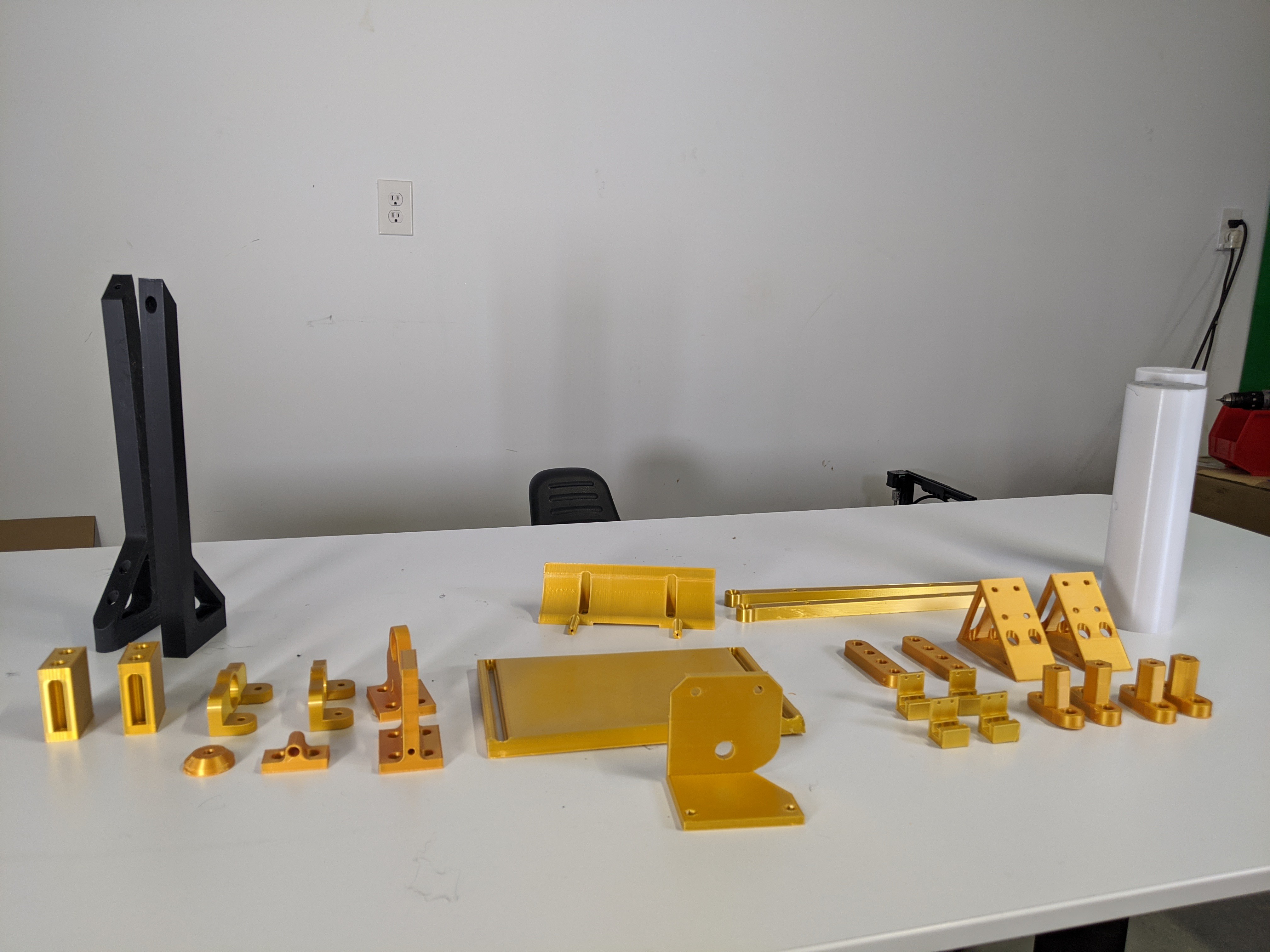
![]() [Figure 3: Parts to be 3D Printed for this Project]
[Figure 3: Parts to be 3D Printed for this Project]All custom parts in this project can be 3D printed. ALL CUSTOM PARTS IN THIS PROJECT CAN BE 3D PRINTED!
A major flaw in my previous conveyor belt 3D printer designs is that some of the parts had to be machined on a lathe, mill, or other expensivew equipment. Obviously, this made the design less accessible to others. Duh!
I want people to be able to build this 3D printer even if they don't have access to their school's machine shop. I want people to be able to build this machine even if they do have access to their school's machine but their faculty is too crusty to let them use it. Therefore, I ensured that all of the mounts, jigs, etc. used in this project can be 3D printed. Once again, the CAD is available in addition to the STL models. So if you want, your more than welcome to machine high quality components out of metal (and if you do let me know!). But 3D printing works just fine.
You can access the CAD repo at this link: https://workbench.grabcad.com/workbench/projects/gcrHAT38NfZQu4oat4sHk3-AmwWRcN0bsbNID3e-RBKutN#/space/gcM1a6sAM3-5xPhVuC2xhwSpQXkVfuiPFueX-V44tka35n
I printed all components at 35% infill and .32 layer height.
Components to Print
Below is the parts lists for the all of the essential components to print. I have also included the CAD files for a few extra unnecessary files in the repo.
[Table 1: Components to Print]
Component Quantity ANGLE_BLOCK 2 BELT_FLATTENER 4 BOTTOM_BRACE 2 BOTTOM_FOOT 2 BOTTOM_LEG 2 BRACE 2 CORNER_BRACE 2 CORNER_BRACE_LONG 2 COUPLER 1 DRUM 2 EXTENSION_BOTTOM 2 EXTENSION_TOP 2 EXTRUDER_BRACE 1 FRONT_BEARING_BLOCK 1 HEATBED_STRUT 2 MOTOR_BLOCK 1 REARING_BEARING_BLOCK 2 SHEAR 1 STANDOFF_MOUNT 4 TENSIONING_BLOCK 2 -
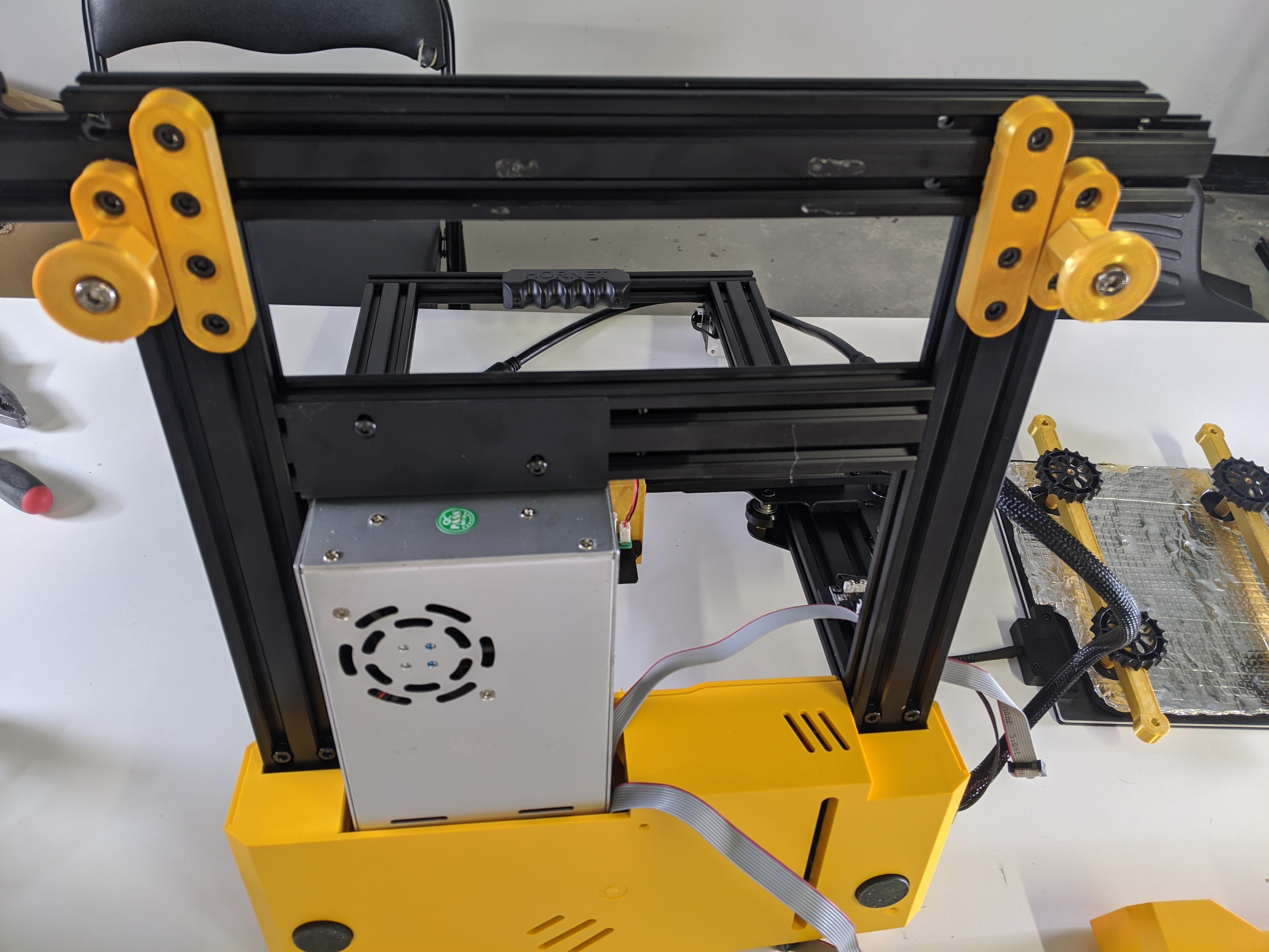
3Remove Y-Axis
![]()
[Figure: Removing Y-Axis]
![]()
[Figure: Salvaging Stepper Motor]
Finally, we can start assembling our 3D printer. And by assembling, I mean disassembling.
My tutorial assumes you are starting this project with a functional fully assembled FDM 3D printer which you want to turn into a conveyor belt 3D printer. I am also assuming your 3D printer has a standard cartesian kinematics system and not some other weird shit (i.e. CoreXY).
The first step we must take is removing the y-axis of the 3D printer. This is the axis that moves the heat bed forwards and backwards. We will be replacing this axis later on with the motion of the conveyor belt.
Unbolt the extrusion that connects the y-axis to the printer and disconnect all of the electronics (heat bed, stepper motor, limit switch) from the main board. Carefully remove the y-axis components and store them in a safe place. Because we are recyclers, we will be reusing all of these components later on in the project.
-
4Assemble Base Extrusion Pieces
![]()
[Figure: Assembling Base Frame]
![]()
[Figure: Base Frame Assembled]
Extrusion is awesome. With t-nuts and an allen key, we can easily mount anything to extrusion; including almost all of the 3D printed components in this project.
The front of the Artillery3D Hornet is a plastic injection molded part. It is not easy to mount things on this part. Therefore, I removed the plastic injection molded piece and replaced it with aluminum extrusion (I reused the extrusion we took out of the y-axis). I connected the aluminum extrusion pieces with the 3D printed "CORNER_BRACE" components.
-
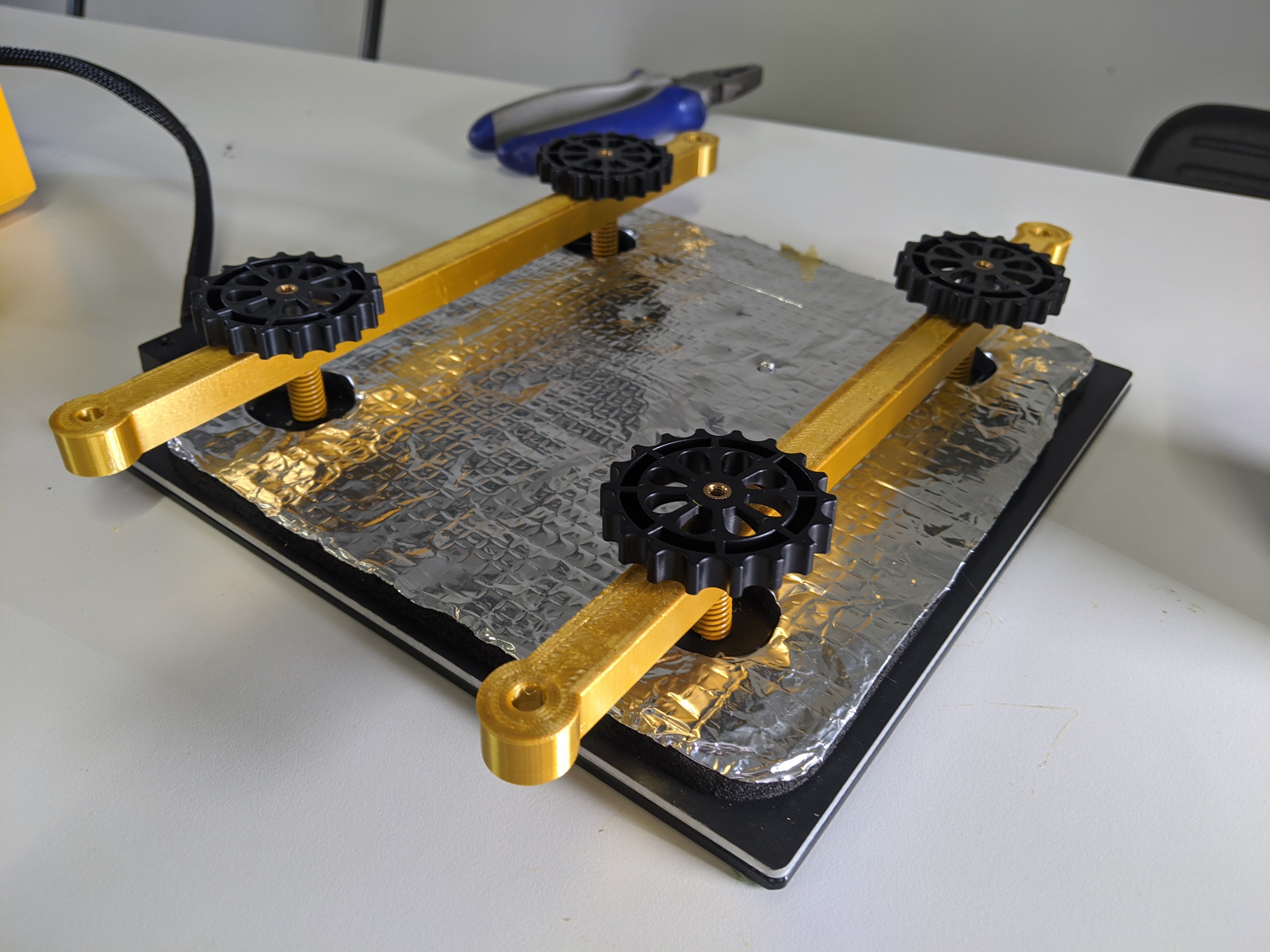
5Mount Heat Bed
![]()
[Figure: HEATBED_STRUT mounted on Heat Bed]
In a conveyor belt 3D printer, the heat bed does not move back and forth along the y-axis. Instead, the heat bed remains fixed in place with the conveyor belt running over it.
Use the "STANDOFF_MOUNT" and "HEATBED_STRUT" pieces to secure the heat bed in place. Your 3D printer likely came with springs to raise and lower the heat bed. Install these springs between the heat bed struts and heat bed for a similar purpose.
-
6Rotate Z-Axis by 45 degrees
![]()
[Figure: Rotating Z-Axis]
With traditional 3D printers, the z-axis is perpendicular to the heat bed. But a conveyor belt 3D printer has the z-axis at a 45 degree angle to the heat bed. This allows the conveyor belt 3D printer to produce infinitely long prints (also the prints have some interesting structural properties).
Unscrew the z-axis from the base of the 3D printer. Use the "ANGLE_BLOCK" and "ANGLE_BRACE" pieces to remount the z-axis at a 45 degree angle to the base.
-
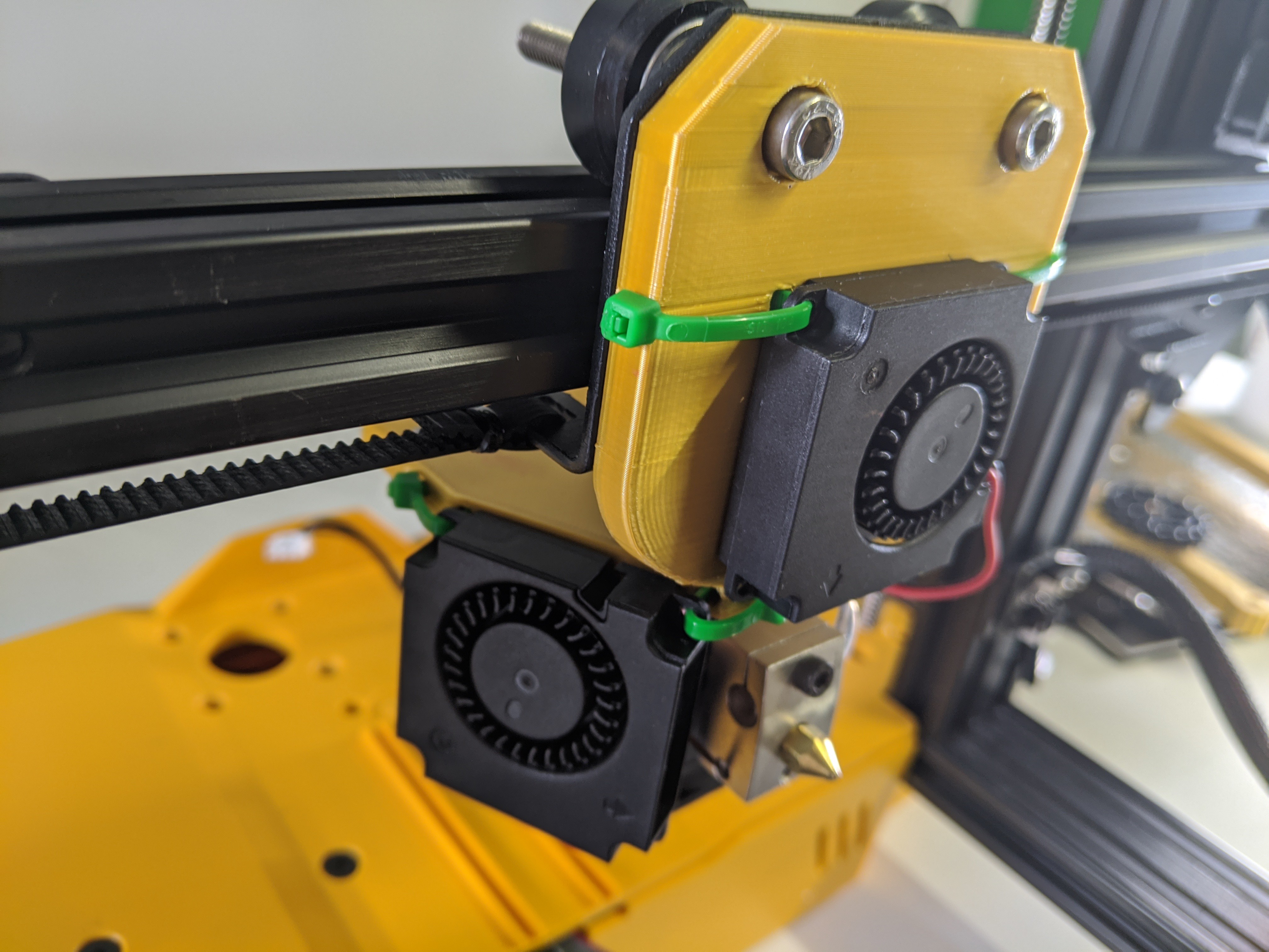
7Rotate Extruder by 90 degrees
![]()
[Figure: Extruder Rotated by 90 deg]
The extruder needs to be rotated as well. Use the "EXTRUDER_BRACE" piece to mount the extruder in a perpendicular position to the z-axis.
-
8Press Bearing into Bearing Holders
![]()
The drums of our conveyor belt must roll on frictionless smooth bearings to function properly. You can salvage such bearings from the y-axis you dismantled earlier on.
Carefully press one of these bearings into each of the bearing blocks. I recommend using a vise or clamp to press the bearings in place.
-
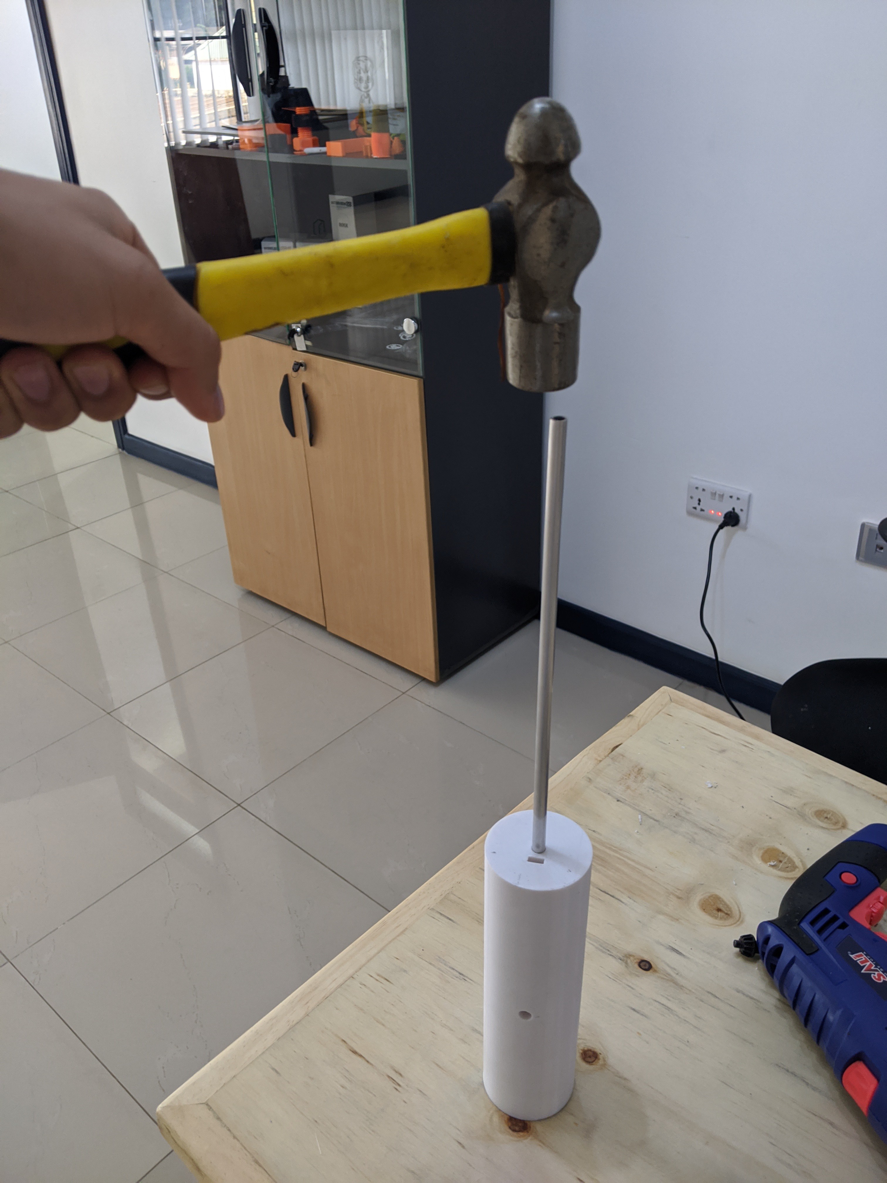
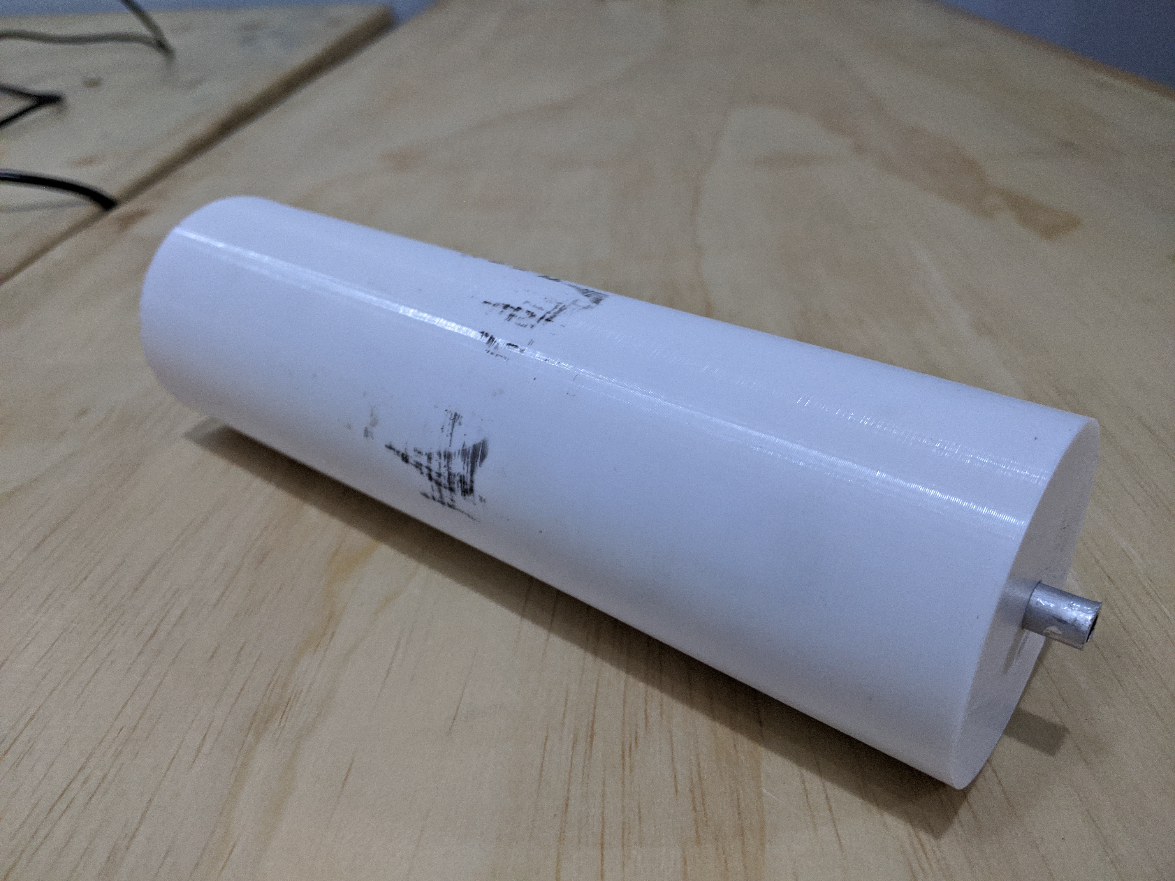
9Hammer axle into drum
![]()
[Figure: Hammering Axle into Drum]
![]()
[Figure: Axle Hammered into Drum]
I lied. Earlier on, I said that all components used in this project could be 3D printed. One component you do need purchase is an 8mm metal axle. Fortunately, it is extremely easy to find this item. Here are a few vendors I found after a 30 second google search: Amazon, Home Depot, Metal Supermarket.
Technically, you can 3D print this component. But I would be afraid of the axle breaking from the shear stress of the conveyor belt.
Once you have obtained a suitable metal axle, cut it into two pieces and hammer each halve into one of the drums. If it is difficult to hammer the metal axle into the drum, I recommend running an 8mm drill bit through the hole of the drum. This ensures there are no 3D printing defects that reduce the hole size.
-
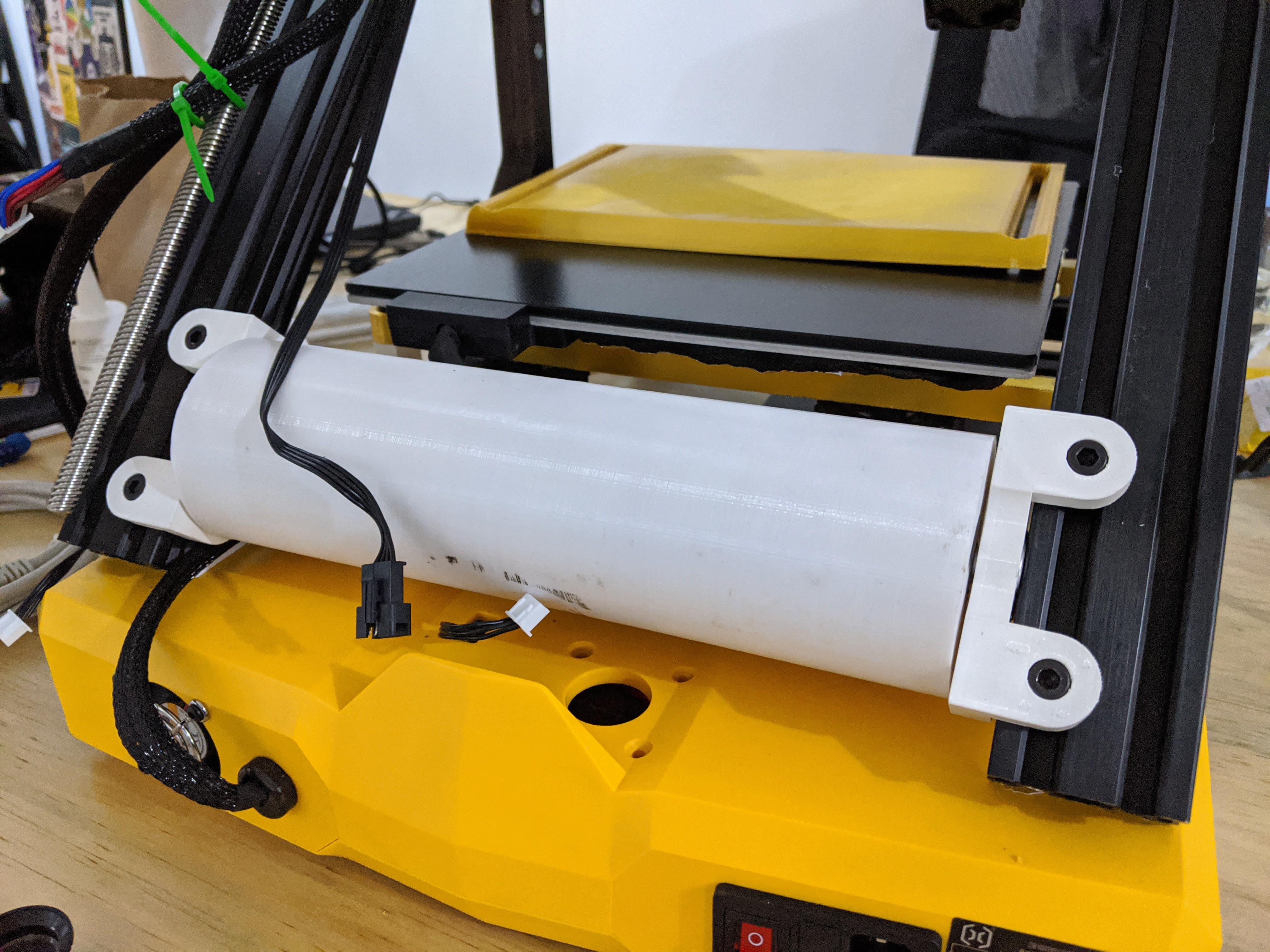
10Mounting Drums
![]()
[Figure: Assembling Motor]
![]()
[Figure: Rear Drum Assembled]
Bolt the y-axis stepper motor to the "MOTOR_BLOCK" components. Than use the respective bearing and motor blocks to mount both drums in place. Use the "MOTOR_COUPLER" component to connect the stepper motor to the drum.
Print HUGE parts with Conveyor Belt 3D Printing
Full tutorial on how to build a conveyor belt 3D printer. I provide completely free and opensource CAD and firmware to build this printer.
 [Figure 3: Parts to be 3D Printed for this Project]
Discussions
Become a Hackaday.io Member
Create an account to leave a comment. Already have an account? Log In.