Tim
Tim-
#007 - TinyDice - Dice on an ASIC
09/03/2022 at 10:24 • 4 commentsDetails
Entry by: Tim
Technology: Skywater 130nm CMOS
Size: 3 DFF, 1 NAND, 1 AND, (1+ AND for clock gating) ~ 10x10µm² on the IC.
This is a submission for tinytapeout that combines 500 very tiny digital designs into a single ASIC to be manufactured by eFabless open shuttle program. The maximum allows space on the die is 100x100µm² and the design can use 8 inputs and 8 outputs. Both, of course, still rediculously oversized for a minimized electronic die!
---------- more ----------
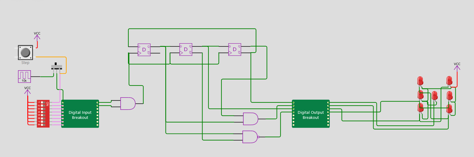
Design entry was done using Wokwi, shown above and linked here. The design is based on the non-inverting johnson counter shown before. Since both positive and negative outputs are available, the decoding logic reduces to a AND and a NAND.
The schematic entry is converted to a verilog source by Wokwi:
 assign io_out[0] = net3;
  assign io_out[1] = net4;
  assign io_out[2] = net5;
  assign io_out[3] = net6;

  and_cell gate1 (
    .a (net9),
    .b (net10),
    .out (net4)
  );
  dff_cell flipflop2 (
    .d (net3),
    .clk (net12),
    .q (net10)
  );
  dff_cell flipflop3 (
    .d (net10),
    .clk (net12),
    .q (net5),
    .notq (net13)
  );
  dff_cell flipflop4 (
    .d (net5),
    .clk (net12),
    .q (net9),
    .notq (net3)
  );
  nand_cell gate7 (
    .a (net10),
    .b (net13),
    .out (net6)
  );
  and_cell gate9 (
    .a (net1),
    .b (net2),
    .out (net12)
  );
endmodule
Then a github action in a github repository fetches this, performs synthesis, placement, routing and layout generation.
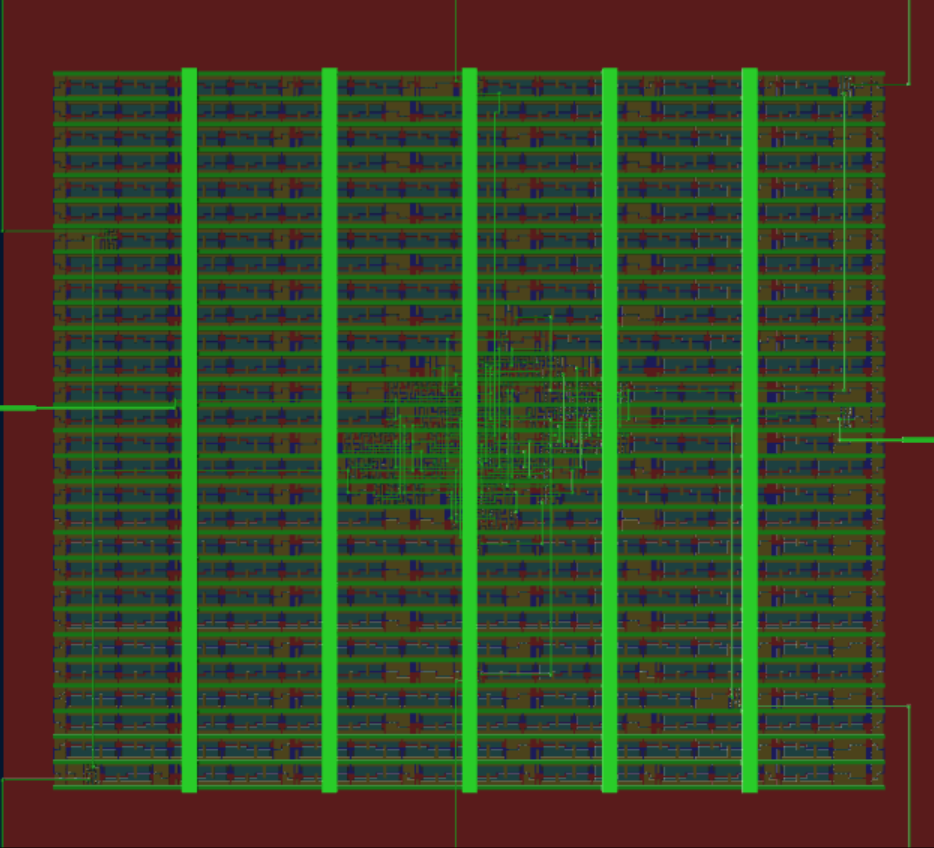
The generated layout is shown above. Only a tiny part of the actualy space is used. And even that is mostly occupied by the scan chain shift registers, that are used to read/write to the 16 I/O pins.
Another design I handed in averaged 50000 cells/mm² for mixed cell types. Based on that, we can assume that the 5 cells occupy 0.0001 mm² or about 10x10µm², one percent of the allowable space. I guess this is surely the smallest electronic die, but maybe not the most efficient one. -
#006 - Dice555-3: "End-game"?
02/15/2022 at 21:25 • 6 commentsDetails
Entry by: Tim
Technology: NE555 freestyle
Size: 3 NE555, 3 Transistors, 11 Resistors, 3 Capacitors, 7 LEDs
![]()
After squeezing the last diode out of the discrete transistor implementation, let's try to optimize the circuit even further. It's time to revisit the NE555 as a main component of electronic dice, because both somehow belong together. I designed an electronic die based on NE555 logic earlier, taking a whopping 21 NE555. This was optimized to only 12 NE555 later, by introducing a Johnson counter. Now let's improve on that. This approach takes a lot of inspiration from the light dice by Dr. Cockroach.
---------- more ----------System Architecture
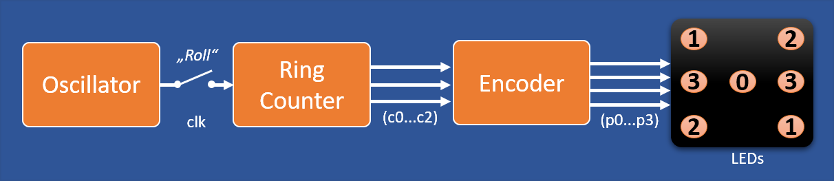
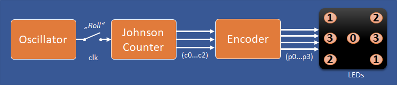
Let's start with the system level again. Our common electronic die system architecture is shown below.
![]()
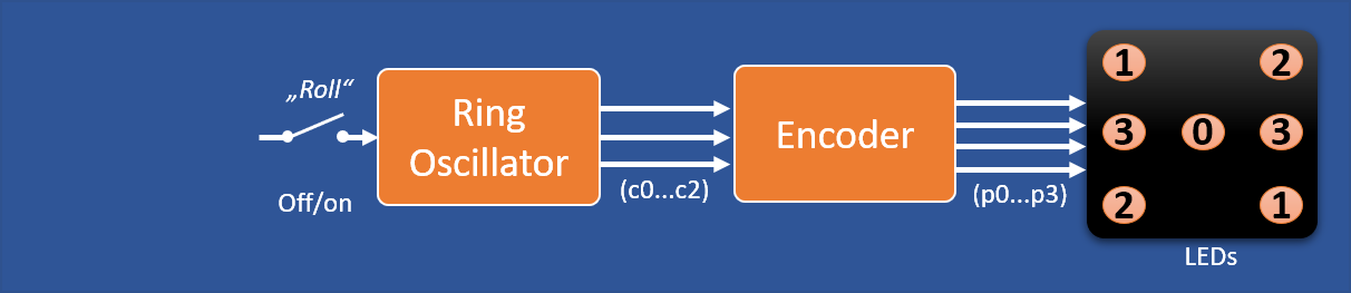
We established before, that the ring counter is the optimum counter architecture and that the encoder can be realized with almost no components by merging Encoder end LEDs. So, how can we improve further? How about merging further blocks of the system:
![]()
Instead of a ring counter we use a ring oscillator. The light dice uses a 7 stage ring oscillator as a counter and freezes it's contents using latches.
Ring Oscillator
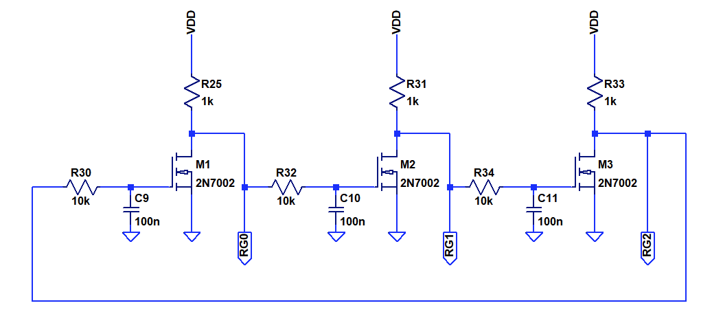
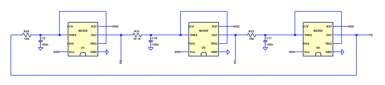
Interestingly, the behavior of a ring oscillator is very similar to that of the "fully inverted johnson counter" we looked at before. Let's take a look at a three stage ring oscillator. Each inverter stage is delayed by adding an RC element so we can observe individual states of the oscillator.
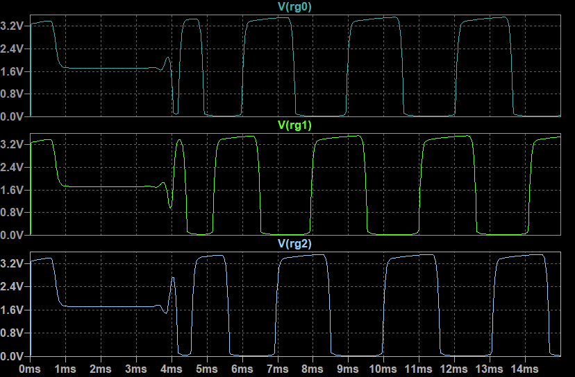
Simulation output after each inverter:
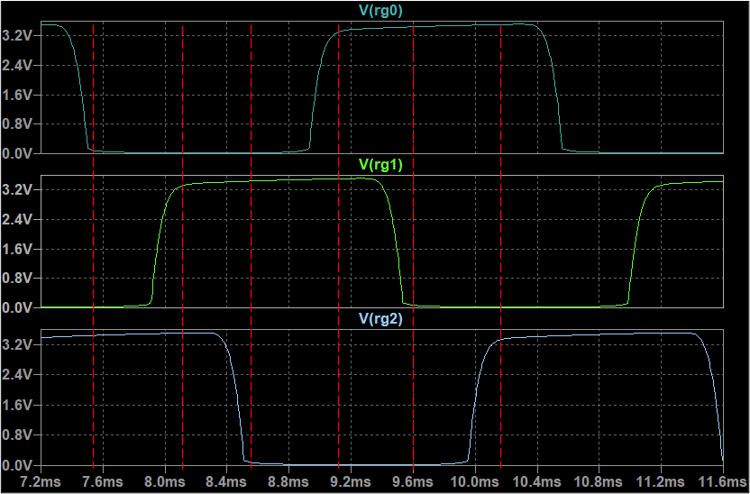
After an initial period of instability, the ring oscillator oscillates with a constant frequency. The outputs are phase shifted by 60°. Let's take a look at the detailed pattern.
Each separate transition represents a new bit pattern. The sequence is: "001", "011", "010", "110", "100", "101" and then it repeats. So, we got a sequence with a length of six, perfect! The sequence pattern is actually the reverse of the "fully inverted johnson counter" that we discussed in the previous log.
The timing looks a bit irregular and the signal shape is not quite digital yet. Let's fix that by introducing some schmitt triggers - enter the NE555s:
The output of this ring oscillator looks almost perfect:
The NE555 introduces a hysteresis with equalized switching thresholds and has much more gain than the disctrete transistor inverter.
Halting the counter
Nice, now we can count through the dice sequence with very little effort. To complete the "roll" it is, however, necessary to stop the counter. One option would be to latch the output, but that would add quite some complexity.
Note that we already have a large capacitor in front of each NE555 that can holds it's charge for quite a while. This alone will be able to store the content of the counter if we disconnect the input from the output of the preceding stage.
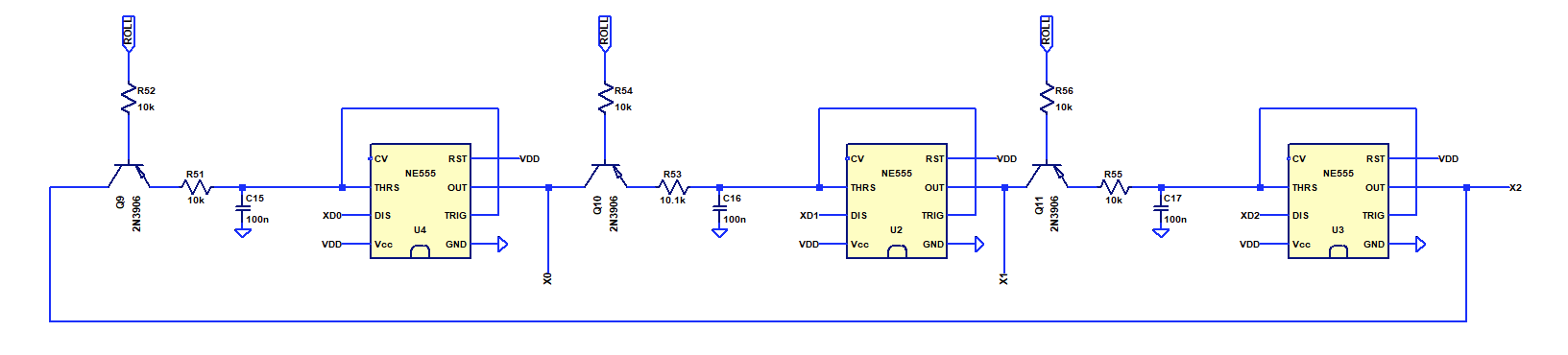
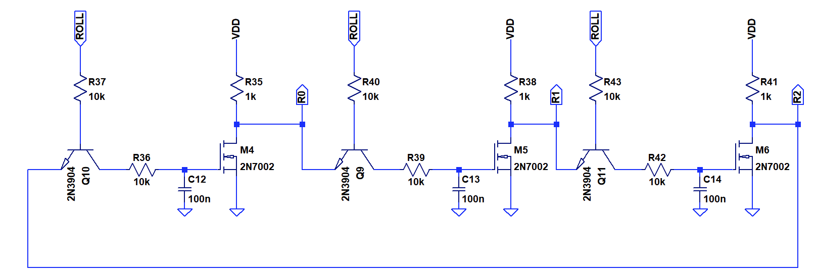
A simple way of implementing this is by using transistors as pass gates:
Alternatively one could simply use a multi-switch. But these are difficult to come by in this millenium and are difficult to synchronize. Here, I used PNP transistors to equalize the voltage drop on high in the NE555.
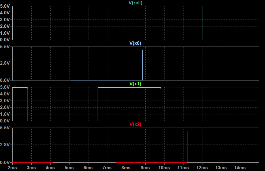
Simulation:The ring oscillator is active while "Roll" is low. Once "Roll" goes high, the current state of the counter is frozen. See 12 ms mark in the simulation.
Yay! Works perfectly. An additional resistor is needed for the "Roll" button.
This concept is also known as "gated ring oscillator" and is employed in time-to-digital converters (TDC) to measure very short time intervals. For example here.
For the eletronic dice we effectively measure the time the "roll" button is held down as a source of randomness.
Component usage: 3 NE555, 3 Transistors, 7 Resistors, 3 Capacitors, 0 LEDs
Encoder and LED array circuit
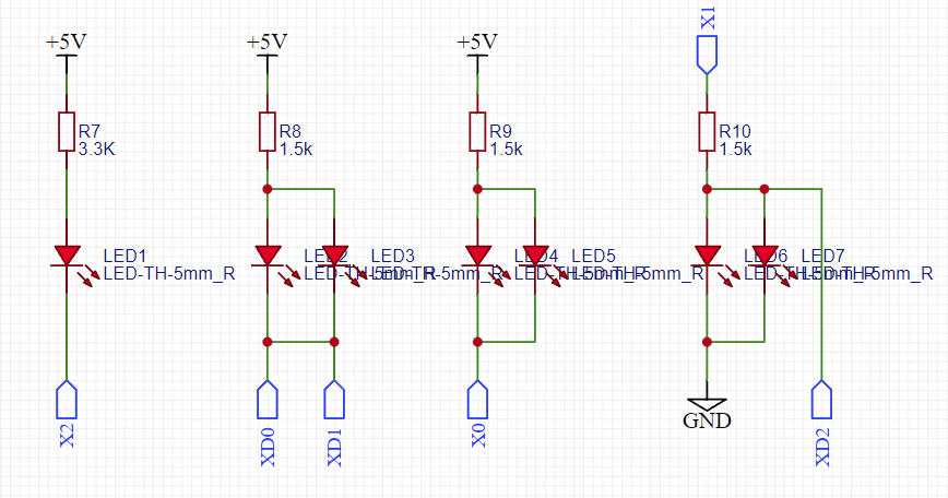
The design of the encoder can basically follow the approachs for the "fully inverted johson counter" from the last log. We can, however, make use of the discharge output of the NE555 to remove the diodes. Circuit shown below. The "XD_" outputs are the open collector discharge outputs of the NE555, while the "X_" outputs correspond to the push-pull outputs.
Schematics:
Can it get any simpler?
Component usage: 0 NE555, 0 Transistors, 4 Resistors, 0 Capacitors, 7 LEDs
Design summary
Ring Oscillator: 3 NE555, 3 Transistors, 7 Resistors, 3 Capacitors, 0 LEDs
Encoder: 0 NE555, 0 Transistors, 4 Resistors, 0 Capacitors, 7 LEDsTotal: 3 NE555, 3 Transistors, 11 Resistors, 3 Capacitors, 7 LEDs
Note that this only corresponds to 26 components in total, half of that of the discrete approach previously. In principle one could replace the 3x NE555 with 1x 74HC14 and two extra diodes. But that would keep the component count the same.
A fully transistorized version would add 3x NFET, 3x resistor and 2x diodes instead of the NE555 - still much smaller than the discrete implementation from the previous log. But due to the low slew rate of the inverters and assymetric threshold, one would also freeze transitional states which would lend an analog touch the the circuit. Schematics:
Consider the drastic reduction in component count compared to the synthesized NE555 logic version.
Can we still improve on that?
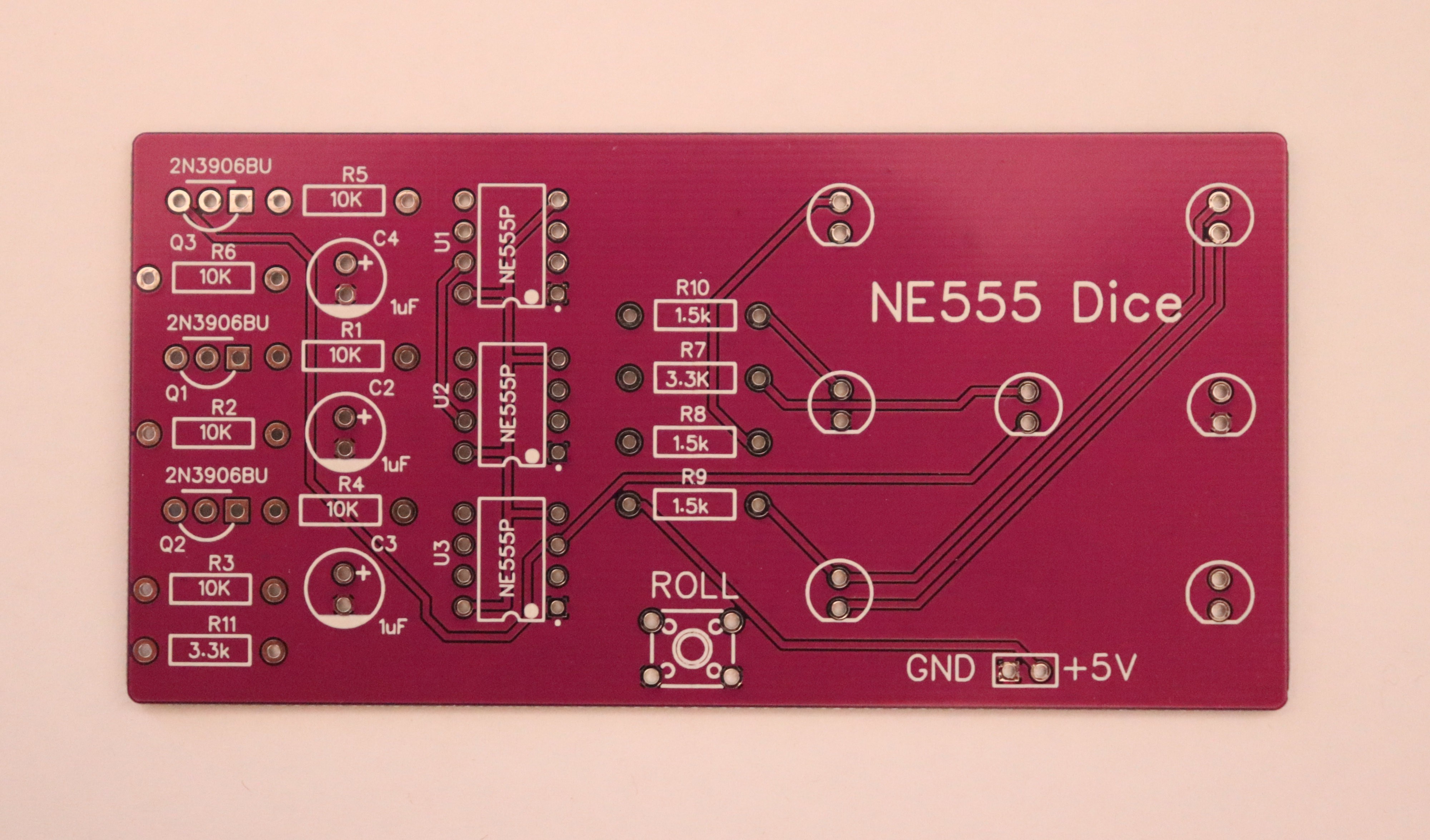
PCB Design
To honour this as a fresh approach to a 40+ years old DIY electronic design kit, I designed a through hole PCB.
Ok, using two layers, grounds planes, and solder resist is somewhat new. I am also shocked about the bad availability and high cost of THT components today...
The PCB is being made right now and I will update with actual hardware.
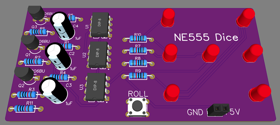
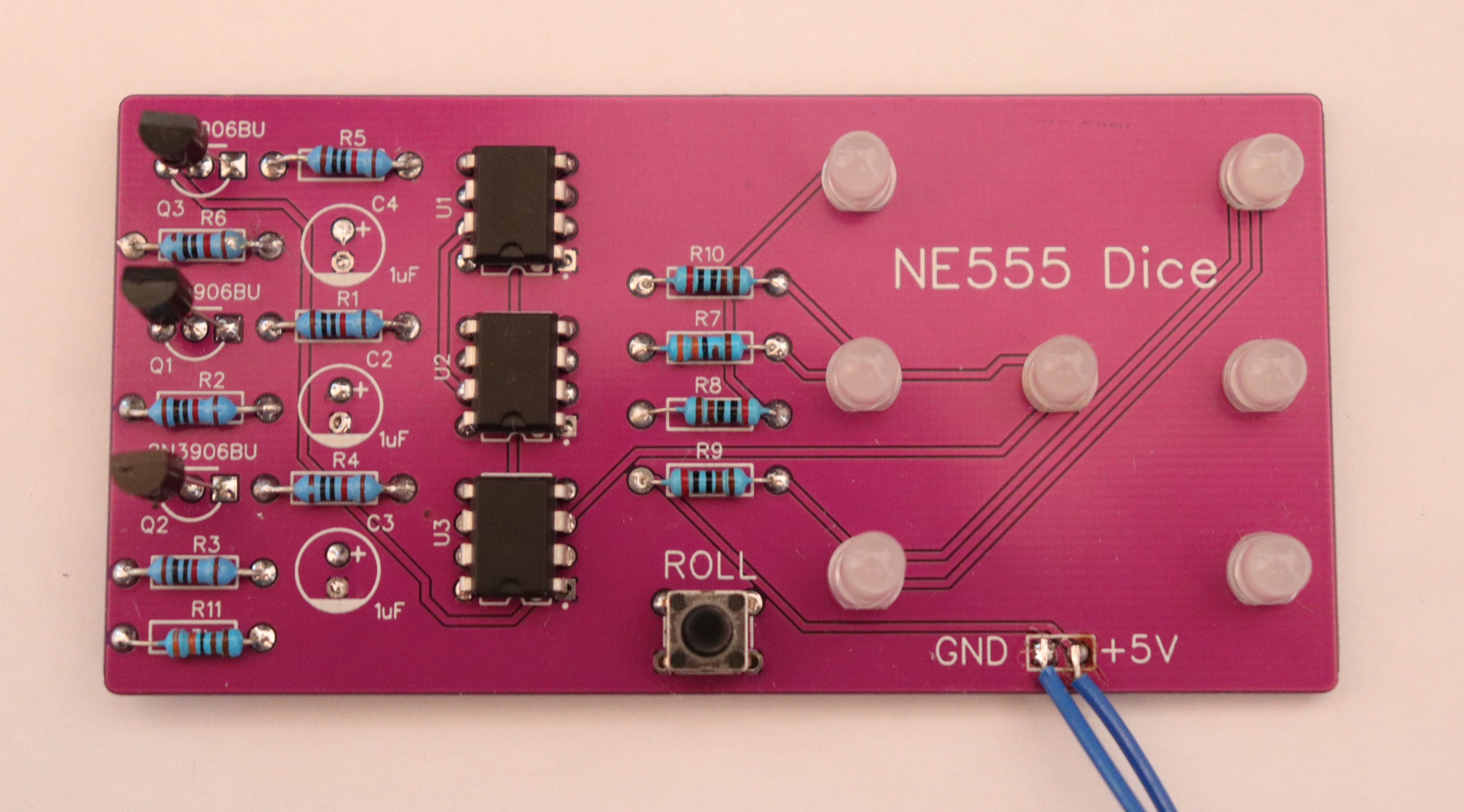
Validation in Hardware
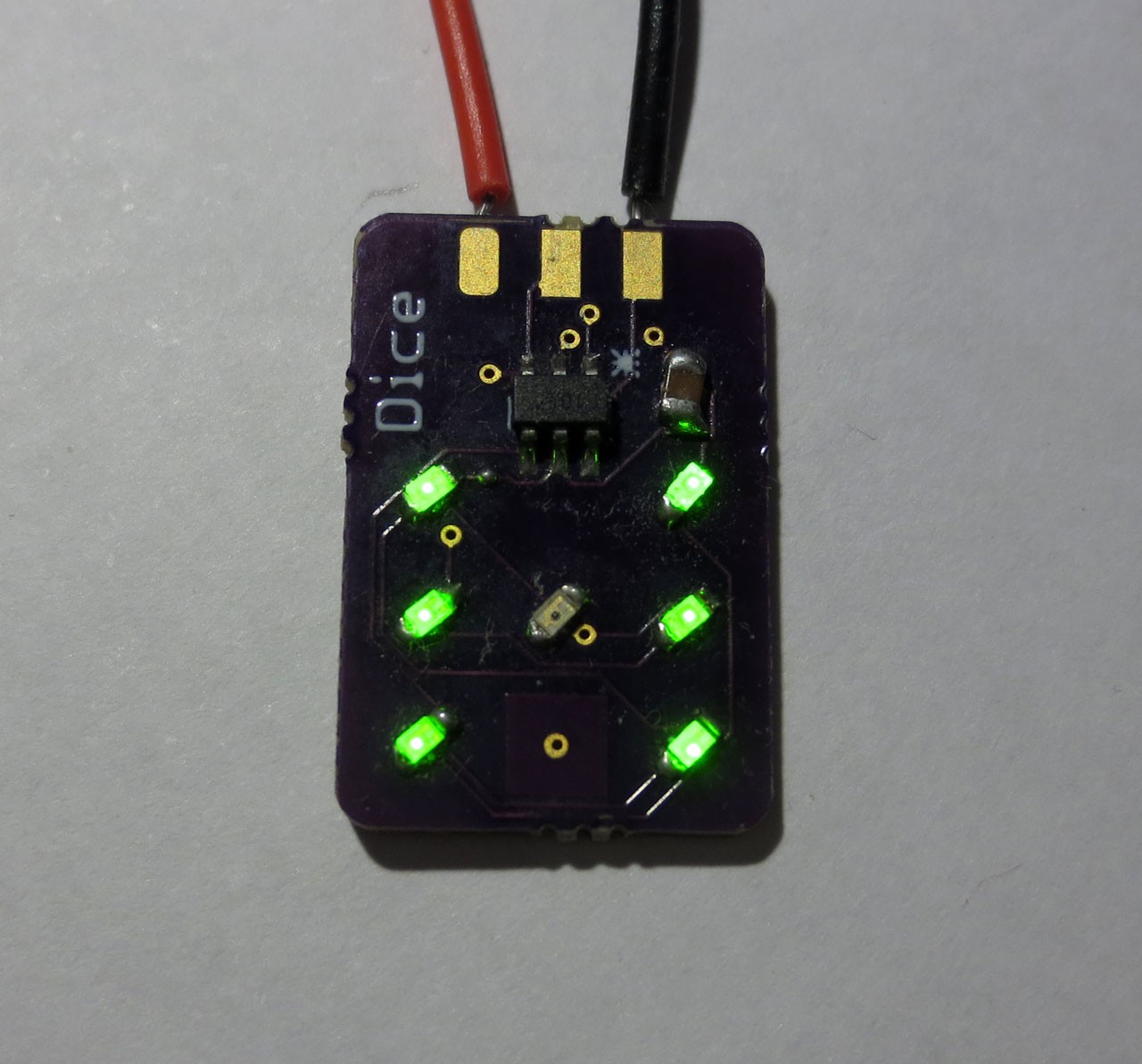
![]()
![]()
Populated PCB. Nice flashback to THT soldering. Somehow SMD is easier in the end, isn't it? I was also surprised about the large size of everything. It didn't looks that large in the design tool :) I could not find fitting electrolytic capacitors, so instead there are SMD caps on the rear side of the board. I have ordered some for a more faithful build, though.
-
#005 - Dice3904-8: Minimal Transistor Based Dice
02/12/2022 at 11:05 • 4 commentsDetails
Entry by: Tim
Technology: Bipolar/Diode logic freestyle
Size: 8 Transistors, 8 Diodes, 25 Resistors, 8 Capacitors, 7 LEDs
(The photo is just a placeholder for later hardware) Architecture-, Logic- and Circuit-Optimization
What is the minimum number of discrete components required to implement the electronic dice functionality? The technology of choice is bipolar logic. Let's try to identify a systematic approach for reduction of system complexity. First, we will look at the system level, then logic level implementation and finally a circuit implementation.
---------- more ----------System Architecture
The general architecture is shown above. The oscillator generates a clock that can be activated with a push-button to roll the dice. The clock cycles a counter through six states. A really neat and effieicnt way of implementing this is with a Johnson Counter with a natural sequence length of six (see also discussion here). The counter output is encoded as three bits (c0,c1,c2) and forwarded the to encoder, which will generate the dice patterns for the LEDs. Since all possible patterns can be generated with only four groups of LEDs, the encoders has four outputs.
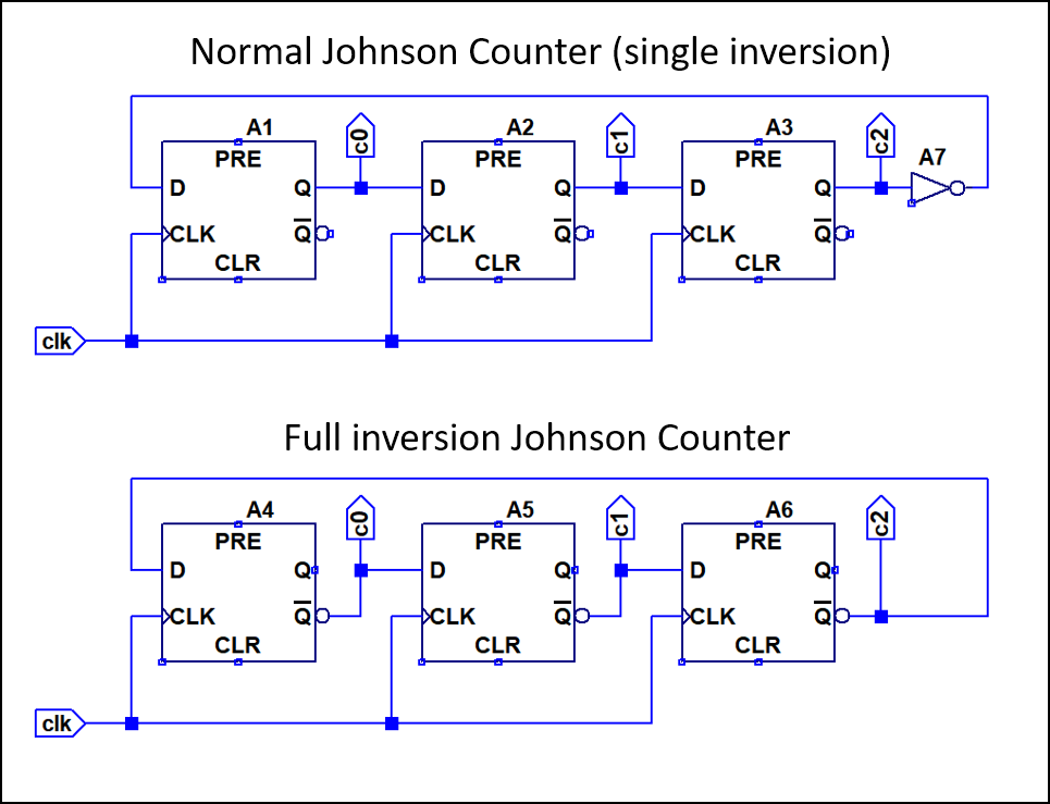
Johnson Counter Logic Optimization
![]()
The counter consists of three clocked flipflops. Normally a johnson counter is implemented with a single inversion at the end of the chain, but for a length of three it is also possible to combine flip flops with inverting output. This can be quite neat in case we have inverting flip flops. No additional inverter is required. On logic level, this is as far is we can optimize, since the counter is basically only flipflips now.
Sequence    Normal Johnson      Fully Inverted
    1           001                   011
    2           011                   001
    3           111                   101
    4           110                   100
    5           100                   110
    6           000                   010
The output sequence of both variants is shown above. Basically the middle bit is inverted for the fully inverted version. In case our flip flops have both inverting and non-inverting output, we can of course use both the inverted and non-inverted sequence.
Encoder Logic Optimization
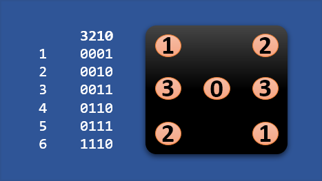
Now to the tricky part, encoding the counter output to the dice pattern (the pips). It appears that the proper way of doing this, would be to assign the sequence order of the counter directly to the value of the die, so that it counts upwards (1,2,3...). However, since the only purpose of the counter is to deliver a random output we can actually ignore the sequence order. This reduces the problem to encoding every counter output to a specific die pattern: we can freely choose the assignments to minimize logic.
![]()
The pip group encoding is shown above. We can see that pip-groups 0 and 2 (p0,p2) basically light up half of the time, so they could be directly assigned to specific bits of the counter output. Group 1 (p1) is always on, except for one combination, which would correspond to an OR, while group 3 (p3) only lights up for one combination which would correspond to an AND.
Diode-Resistor-LED Logic
A neat way of implementing the encoding is to combine it with the LEDs. By using combinations of normal silicon diodes, LEDs and resistors it is possible to implement a wide range of logic functions. Therefore we should consider the constraints given by this implementation when optimizing the encoder logic level implementation.
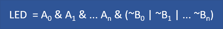
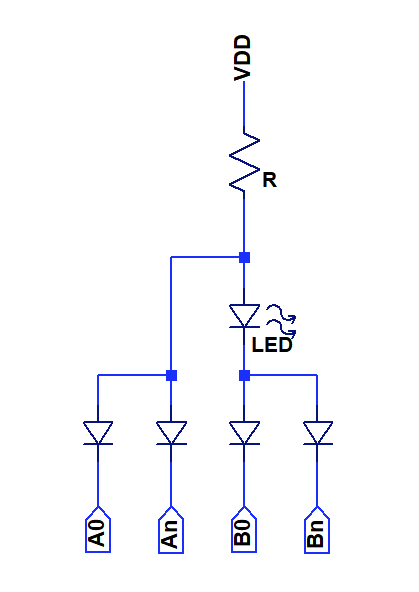
Consider the generic circuit below, that shows possible combinations of diodes and LEDs.
The LED will light up, when any of the Bx input goes low. When any of the Ax inputs is low, the LED will be turned off, since the foward voltage of the diode parallel to it is lower than that of the LED.
![]()
This means that the circuit can implement any logic function that can be represented by the equation above using diodes only. As an additional optimization, it is possible to omit the diode if there is only one A or B term.
Great, now we have clarified input sequence, output sequence and solution space. The professional way would now be to use some kind of logic minimization tool to indefiy an optical solution for the input output mapping, but i made good progress doing it manually, so i skipped that step.
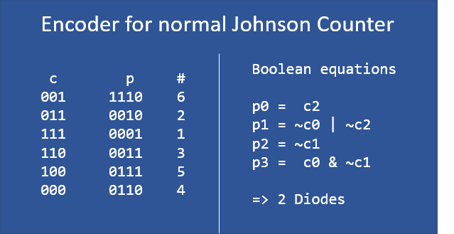
Solution for single inversion Johnson Counter
![]()
Only two diodes are needed to implement term p1, all other terms can be directly implemented by connecting LEDs to the counter outputs. Pretty neat!
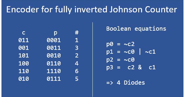
Solution for fully inverted Johnson Counter
![]()
The fully inverted counter is slightly more complex to decode, requiring diodes for terms p1 and p3, 4 in total. The potential reduction in complexity of the counter is outweighted by the more complex encoder.
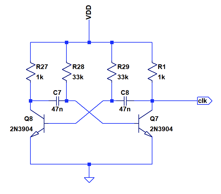
Circuit Implementation of the Oscillator
I played a bit with the garner oscillator suggested by Ken Yap, but could not get it to oscillate in Spice despite trying various initial conditions. It appears to me that there is a metastable non-oscillating state.
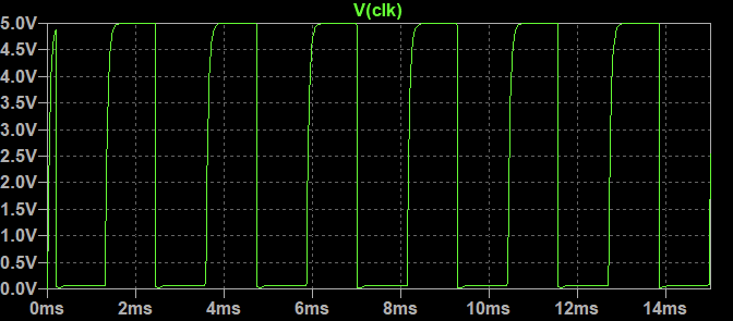
In the end I elected to go with a simple astable multivibrator as shown below.Component usage: 2 Transistors, 0 Diodes, 4 Resistors, 2 Capacitors, 0 LEDs
Simulation output above
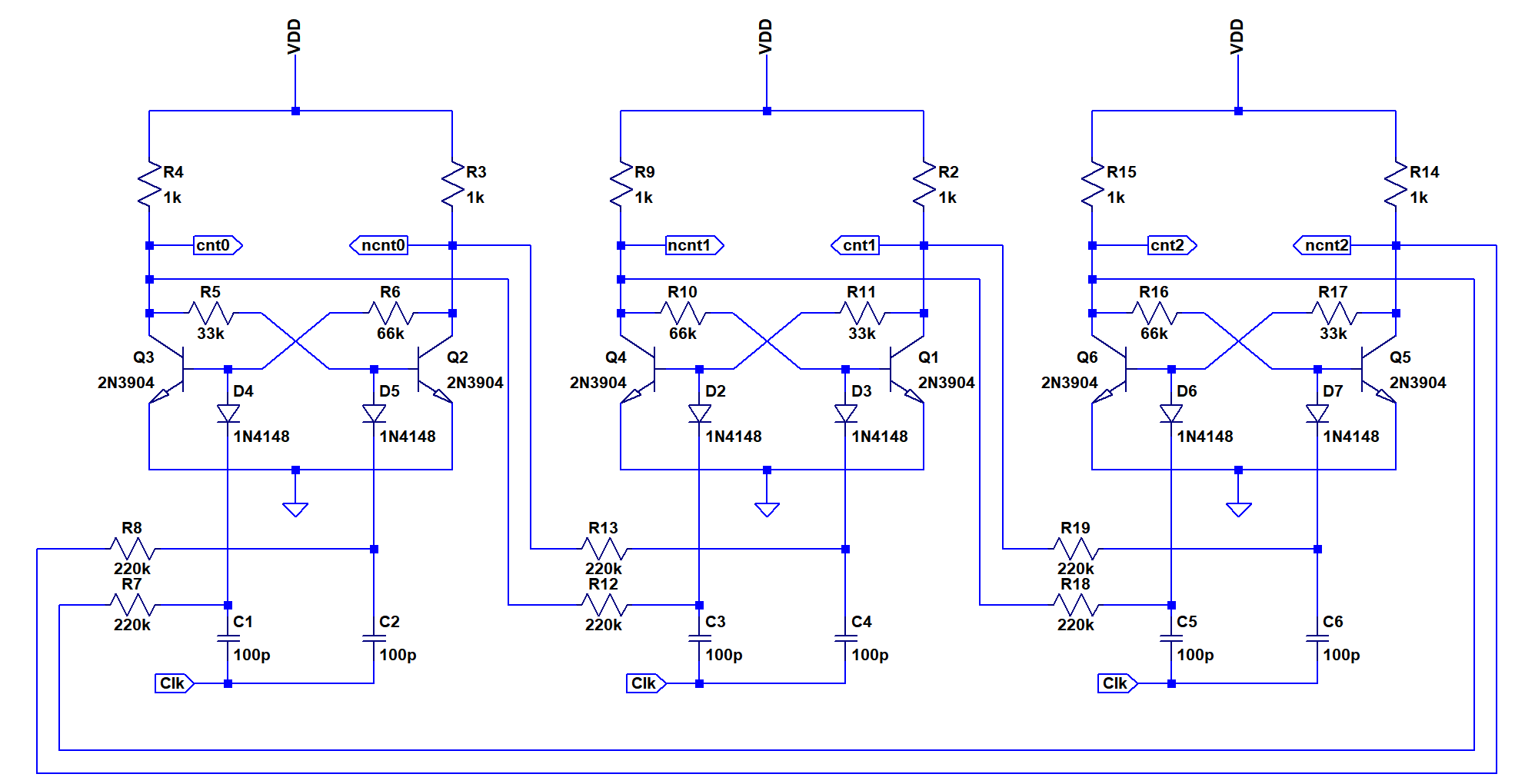
Circuit Implementation of the Counter
The johnson counter consists of three clocked D-Flipflops that are implemented using a capacitor/diode pulse gate. The schematics are shown below. This is a pretty common circuit in 60ies style discrete logic but a bit temperamental when it comes to adjusting it to slew rates etc. The oscillator supplies a sharp falling edge, which works will with the implementation. The benefit of this circuit style is that it is very low in component count. A D-Flipflop implemented in static resistor-transistor-logic (think CDC6600) would require around 6 NOR gates with 13 transistors in total.
![]()
The base resistors are intentionally unbalanced to ensure that the flipflops power up to a defined state that is not equal to one of the forbidden states in the johnson counter ("101" and "010").
Component usage: 6 Transistors, 6 Diodes, 18 Resistors, 6 Capacitors, 0 LEDs
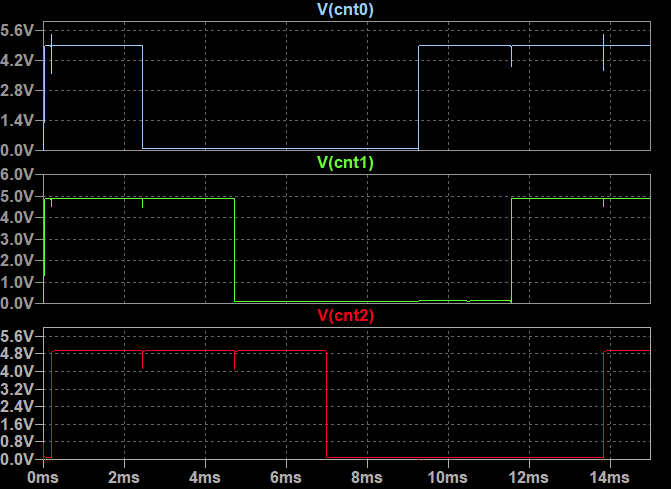
Simulation output is shown above, the sequence is "111","110","100","000","001","011"
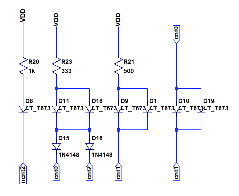
Circuit Implementation of Encoder and LEDs
The implementation of the encoder with LEDs is shown below. As discussed before, only two diodes are needed.
Component usage: 0 Transistors, 2 Diodes, 3 Resistors, 0 Capacitors, 7 LEDs
The simulation output is shown above. All six die patterns are displayed.
Design Summary
Component usage
Oscillator: 2 Transistors, 0 Diodes, 4 Resistors, 2 Capacitors, 0 LEDs
Counter: 6 Transistors, 6 Diodes, 18 Resistors, 6 Capacitors, 0 LEDs
Encoder: 0 Transistors, 2 Diodes, 3 Resistors, 0 Capacitors, 7 LEDsTotal: 8 Transistors, 8 Diodes, 25 Resistors, 8 Capacitors, 7 LEDs
Not bad at all for a fully discrete solution. Is there anything that could be taken away? On to building the hardware, or is there more?
-
#004 with old low-voltage Russian relays
02/10/2022 at 18:35 • 7 commentsI know I know it's only a sim. For now. Because Falstad's CircuiJS is getting better at simulating relays and such. So bear (and raccoon) with me for a while, because it will be a snap to implement for real, right ? :-P
As usual I design this around the old RES-15 relays, SPDT, with the following parameters in circuitjs:
- Inductance : 28mH
- On resistance: 1m ohm
- Off resistance: 1G ohm
- On current : 50mA
- Off current: 30mA
- Coil resistance: 38 ohms
- Switching time: 3ms
The 3ms is an approximation but it gives an idea of the speed that the circuit can reach.
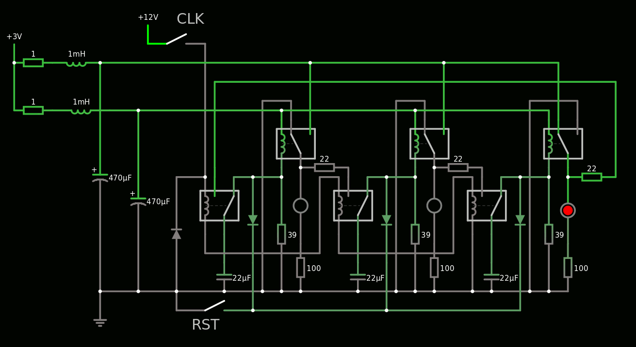
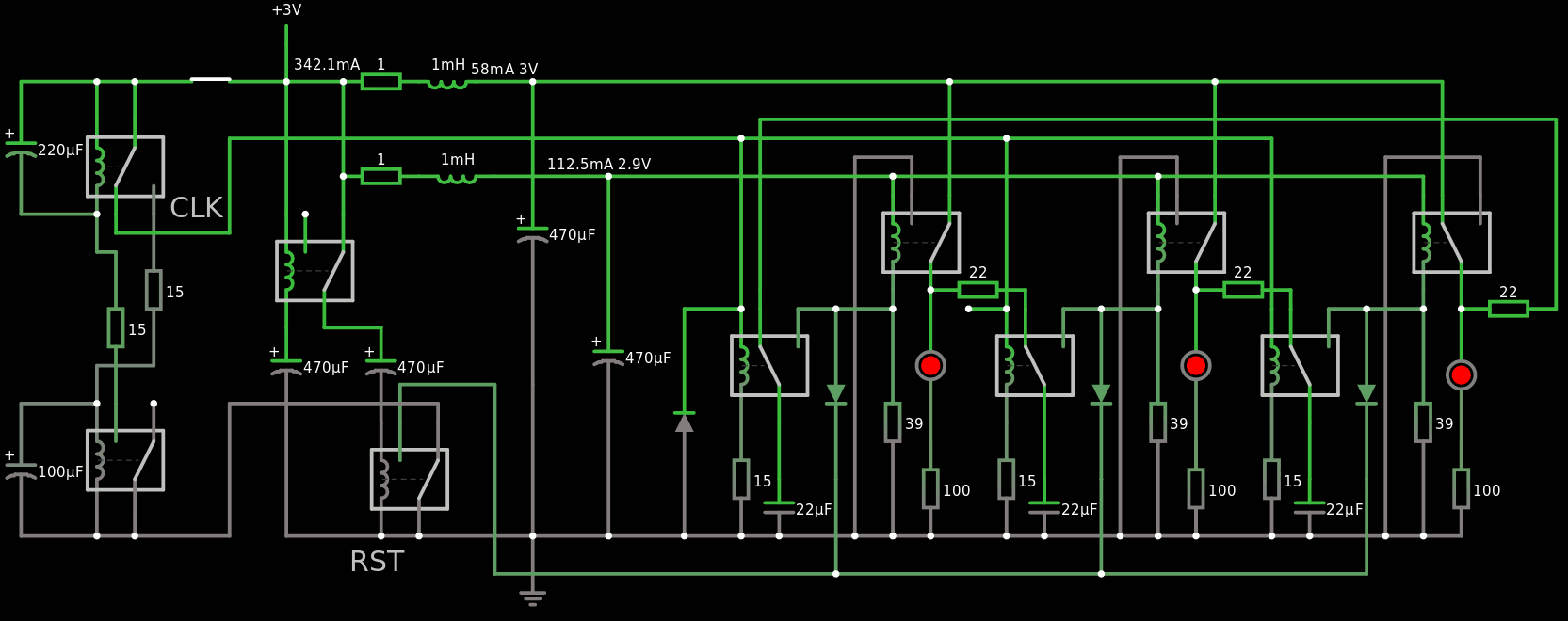
The heart of the system is a 3-stage Johnson counter, made of 3 DFF which use hysteresis for latching. Each DFF has a SPDT capacitive temporary latch to separate each stage. That makes at least 10ms overall, 100Hz max.
![]()
You can even play at home online !
The clock though is a different beast. It must be fast enough but not too fast or the JC can't follow and will end in an invalid state.
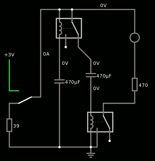
But while seeking a suitable system, I managed to find an innovative (?) Power-On-Reset circuit !
![]()
It has some interesting features :
- it waits for a first period, while the power supply's capacitors charge.
- it then send a pulse for another period
- the timing depends on the power voltage, the capacitance and the relay's resistance
- there is no shorting of the capacitors to the ground, which damages the relay's contacts
- uses only electrolytic capacitors for high storage, easier to source, since the circuit does not drive them in reverse polarity (at least significantly)
- Low quiescent current
- a proper POR simplifies the JC because there is no extra logic to design for the prevention of illegal states.
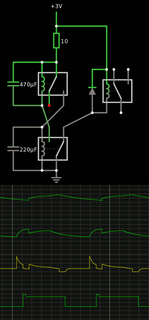
The oscillator is totally... unexpected. That's not what I wanted but it seems to work.
No, seriously, this thing is so weird. But it provides 2 outputs, one contact to 0V and one to 3V, so it can drive a buffer or something like that.
![]()
If you don't believe me, try by yourself.
So far : 10 relays for POR, JC3 and OSC.
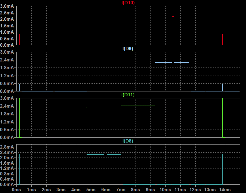
Together, they work nicely, I added some nice touches to reset the clock as well for example, and run on 3V 400mA:
![]()
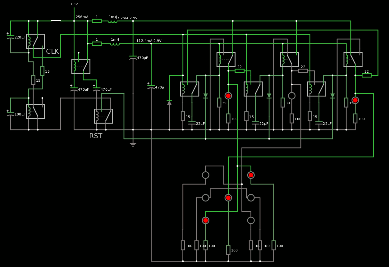
I need an efficient decoder now.
It seems that directly connecting each stage of the JC3 to a pip gives the sequence 1-3-5-4-2-0 so we're almost there!
![]()
All I need is to get rid of the 0 state and output 6 instead, right ?
I'll update the log when I progress...
-
#003 - Dice10: ATtiny10 and only two GPIO!
02/10/2022 at 07:18 • 5 commentsDetails
Entry by: Tim
Technology: AVR ATtiny10 MCU
Size: 1 ATtiny MCU in SOT23-6, 7 LEDs, (1 Capacitor for decoupling)
![https://cdn.hackaday.io/images/4319631480163670824.jpg]() ---------- more ----------
---------- more ----------Description
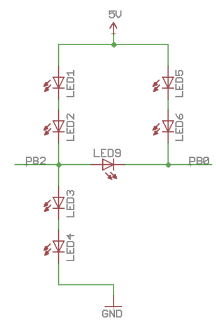
#Dice10 is an older project from a few years ago. It uses the smallest possible MCU in a transistor-like package with only 6 pins and no additional parts except the LEDs themselves. It is probably as small as one could make a MCU based die. Using a MCU is cheating somewhat, so we have covered that now.
The secret sauce is in the way the LEDs are controlled: A multiplexing scheme using ternary signalling allows to controll all seven LEDs from only two pins. More details here. The "roll" is initiated by capactive touch sensing that's implemented in software in the MCU, so no additional components are required.
-
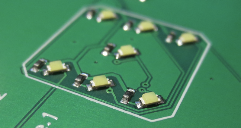
Light Dice
02/09/2022 at 20:05 • 15 commentsThis project can be found at https://hackaday.io/project/183942-light-dice
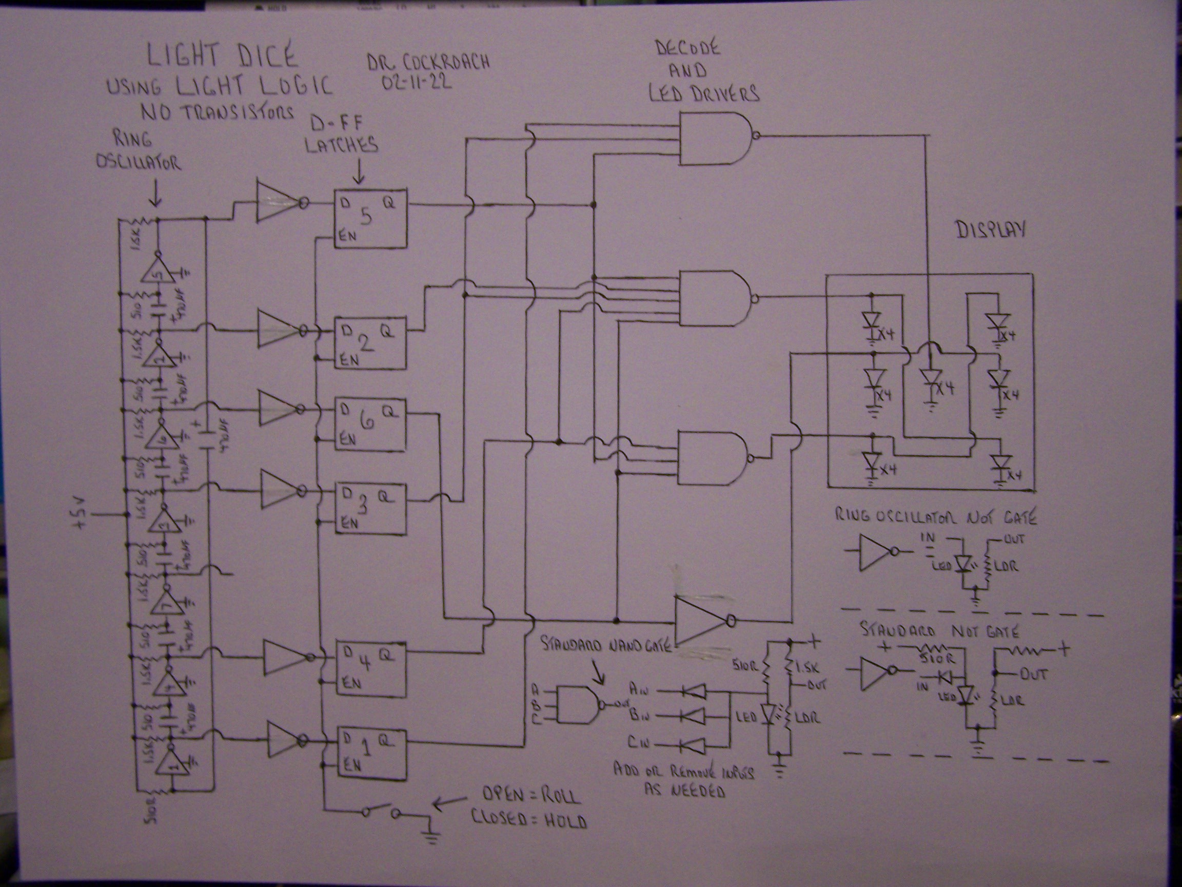
The logic circuit drawing.
![]()
Light Dice, Where Light Logic learns how to roll....
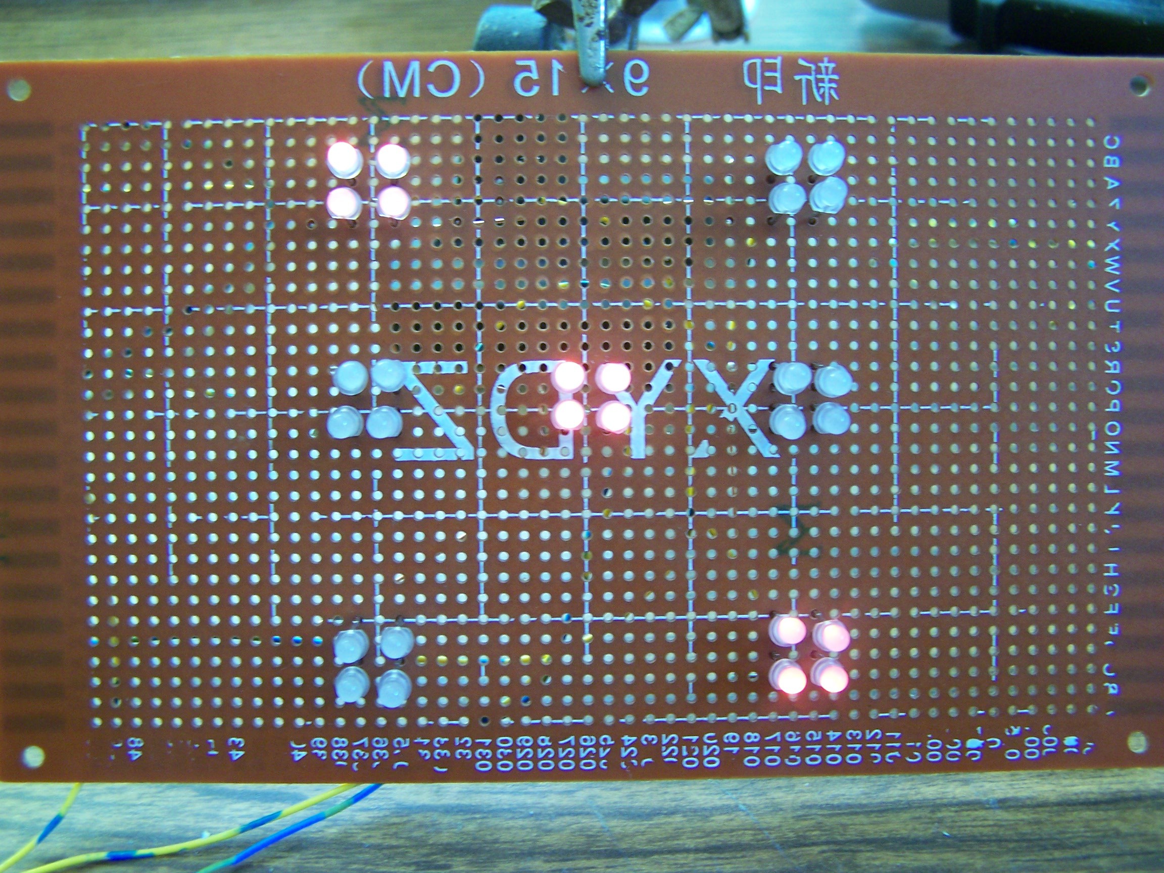
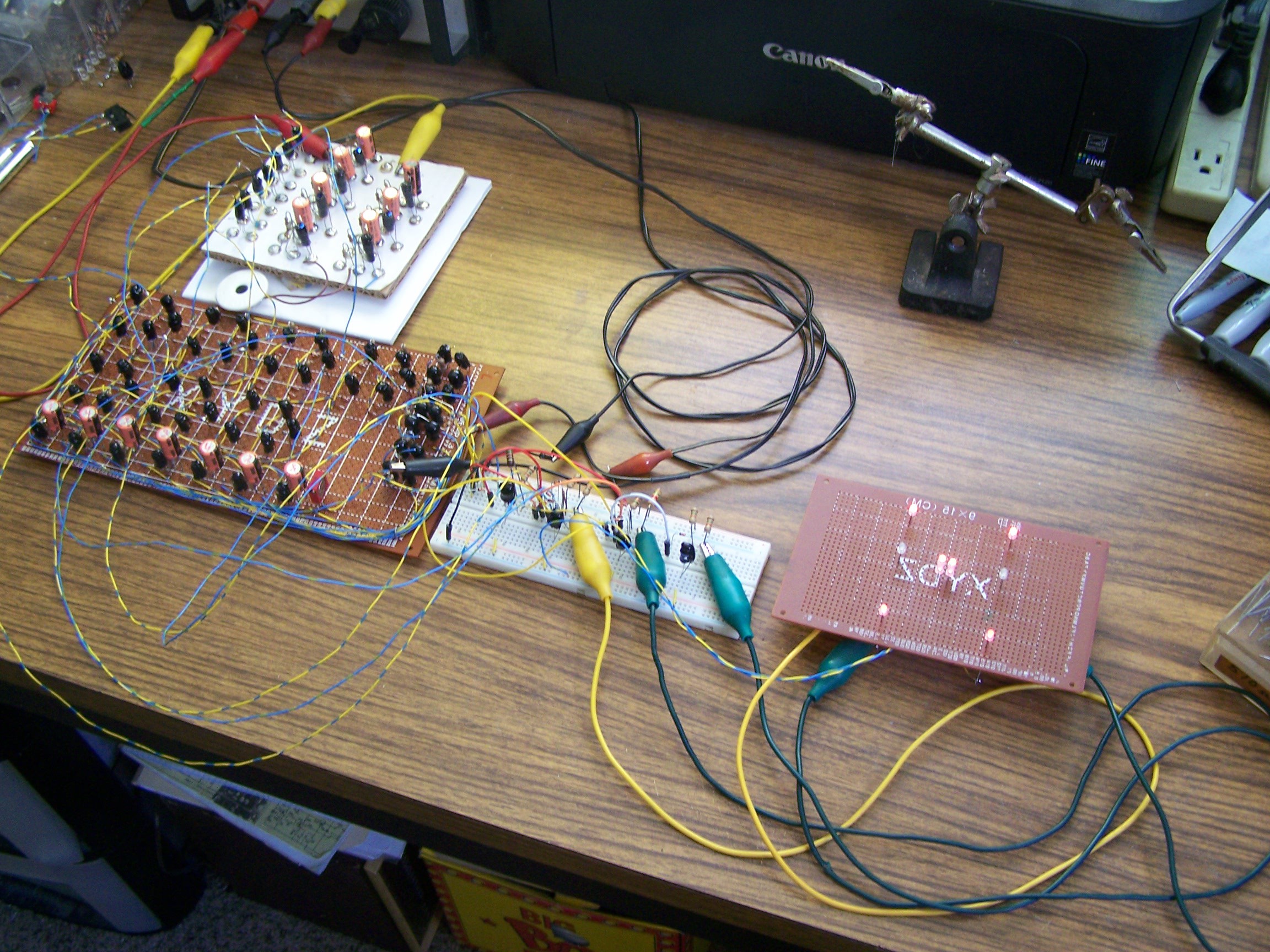
Enhanced led display. Yes, the board is printed like that :-D
![]()
![]()
Putting a ring oscillator, some D latches, a few Nand gates and a dice display together and using only Vactrols. A video and a circuit will be forth coming.
-
#001 - A classic 74XX TTL implementation
02/09/2022 at 19:58 • 0 commentsDetails
Entry by: Tim
Technology: Pure 74XX TTL
Size: 5 TTL ICs, 7 LEDs, 4 Diodes, 5 Resistors
![]() ---------- more ----------
---------- more ----------Description
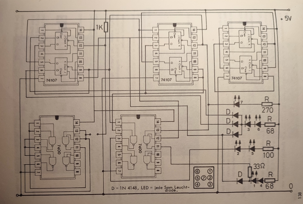
This was not designed by me, but I found it in an ancient book from 1977 that I inherited . Of course we should rather report our own designs, but I will make an exception to set the bar low?!
This is a pure 7400 TTL implementation, taking five chips in total. You surely can beat that?
One curious fact is that it uses a ring oscillator based on NAND gates (lower left SN7400) as the clock. This will certainly ask for trouble when you start mixing logic IC with different propagation delays, but it appears this is fine when using only original TTL IC.
Circuit Golf: Electronic Dice Edition
Creating Electronic Dice with the least number of components in the most obscure technologies
 The generated layout is shown above. Only a tiny part of the actualy space is used. And even that is mostly occupied by the scan chain shift registers, that are used to read/write to the 16 I/O pins.
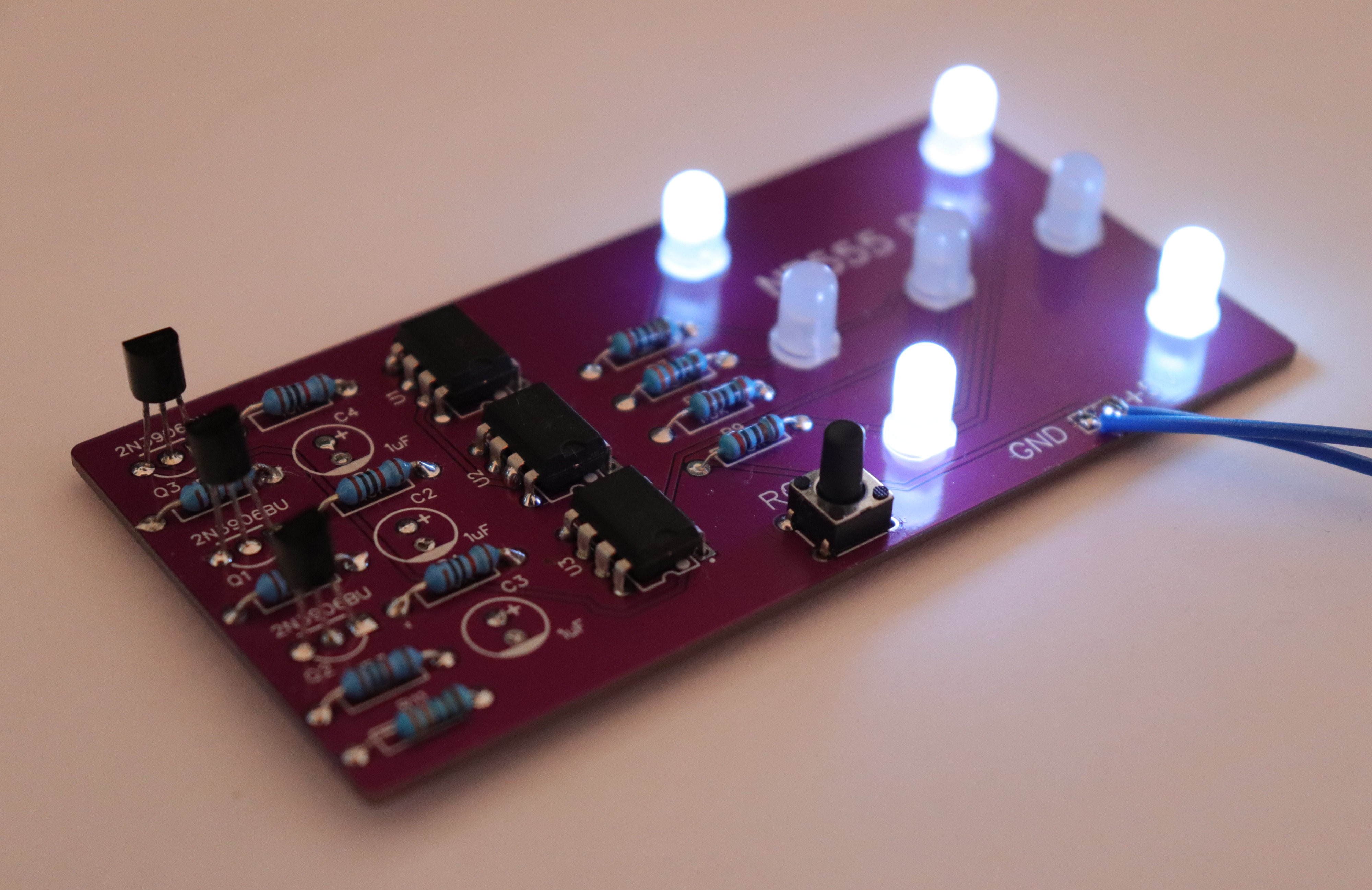
 The output of this ring oscillator looks almost perfect:
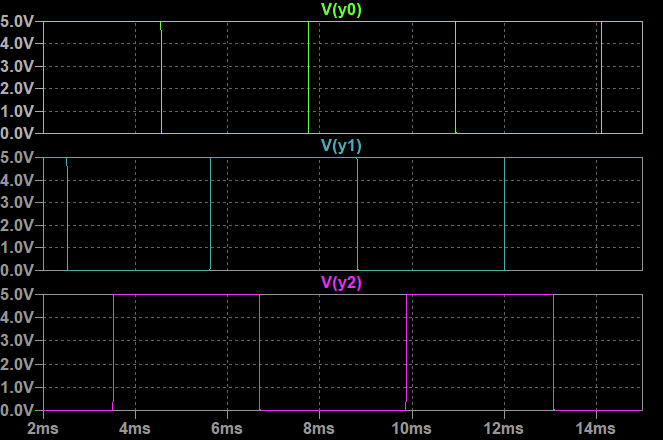
 Consider the drastic reduction in component count compared to the
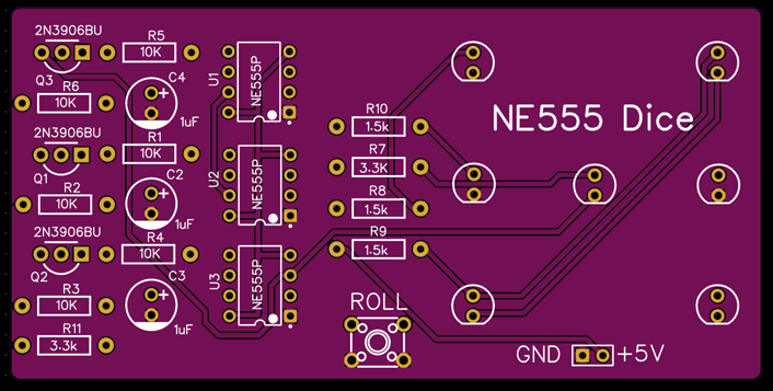
 The LED will light up, when any of the Bx input goes low. When any of the Ax inputs is low, the LED will be turned off, since the foward voltage of the diode parallel to it is lower than that of the LED.