Close
0%
0%

Radiation King Radio

A Pi based music player with simulated live station playback, analog controls, and a 1950s era ultrasonic remote.

Similar projects worth following
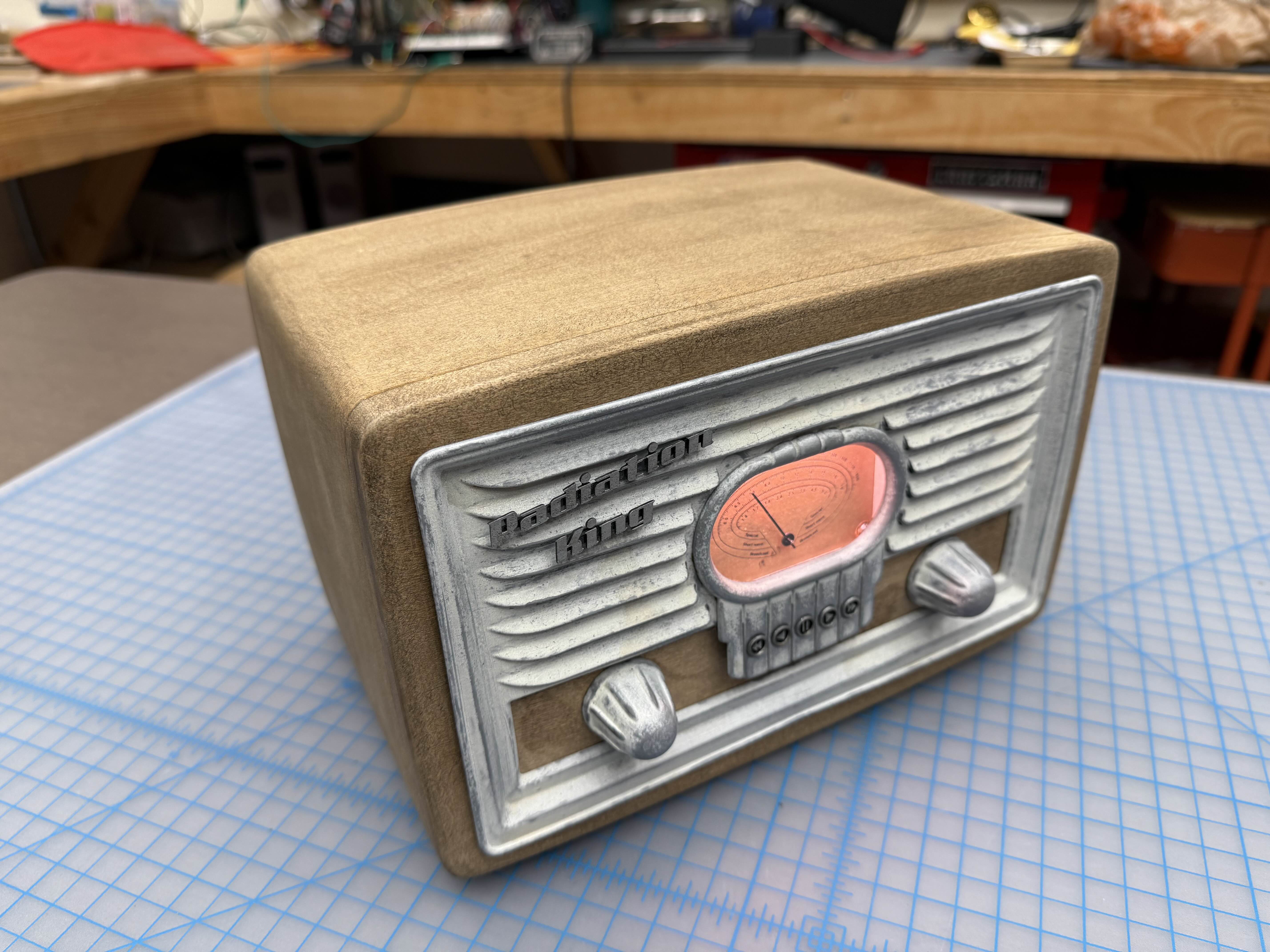
My goal is to create the table-top radio as seen in Fallout 3 and 4. (See rendering)

Using custom time-based coding, the software create simulated live radio stations. You can tune the dial and it has the feeling of an old-school AM/FM radio.

The software can automatically parse folders and files into virtual radio bands and stations. Station playback can be ordered or random to allow for audio drama series, or just music playback.

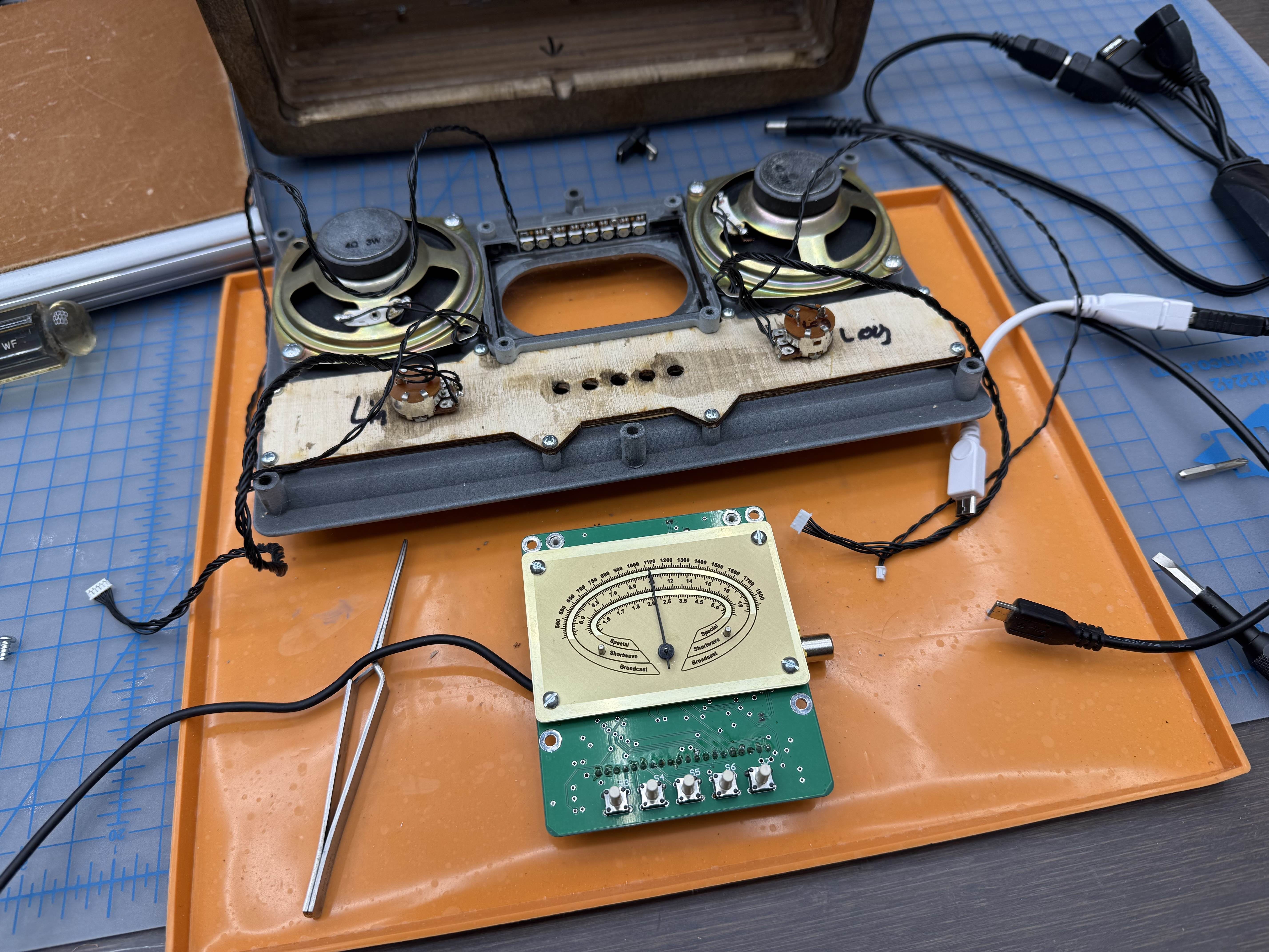
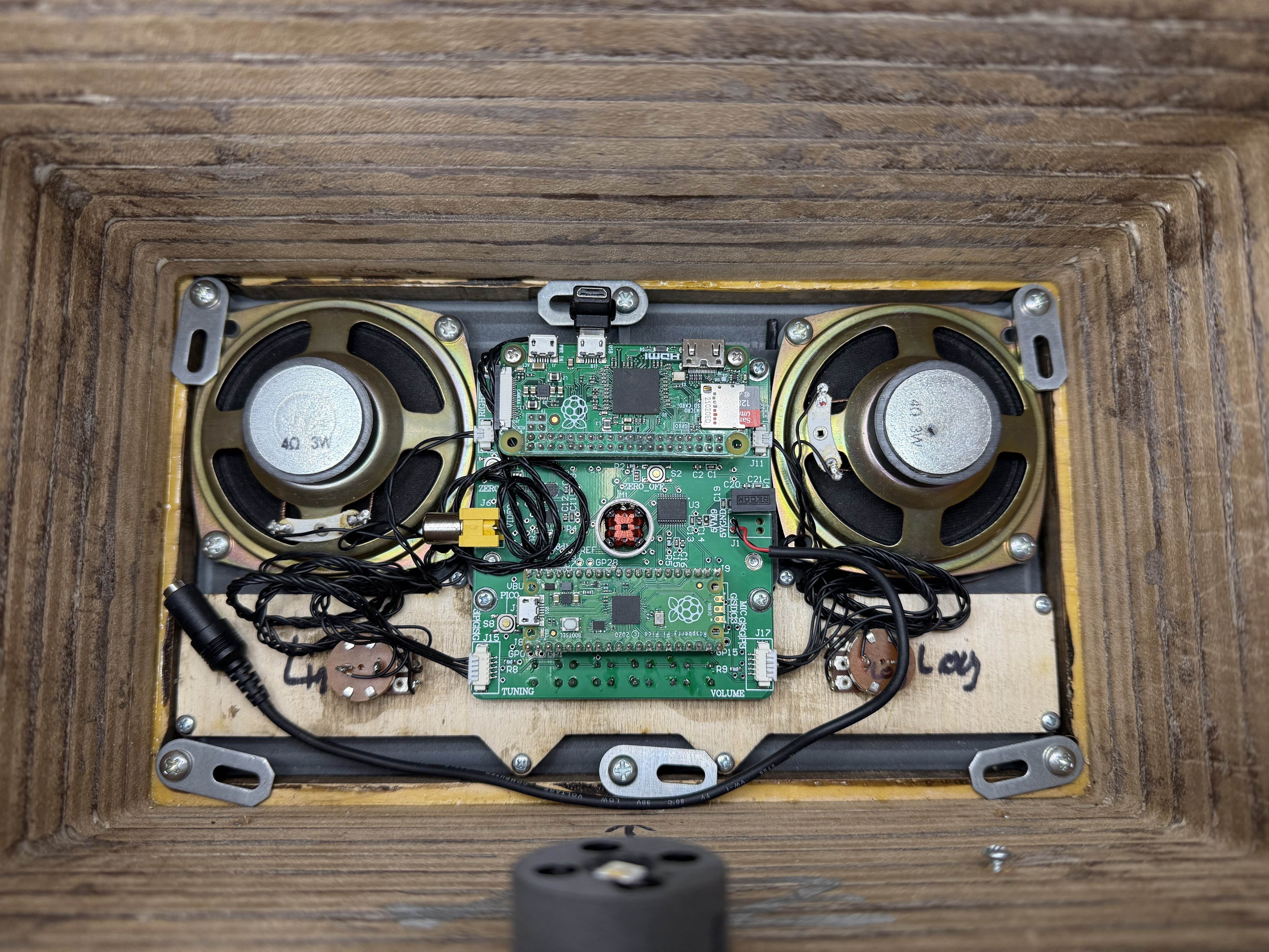
A Pi Zero handles the music playback, and a Pi Pico handles the rest.

An air-core motor is used for smooth analog needle control, rather than the jittery movement that a stepper motor provides.

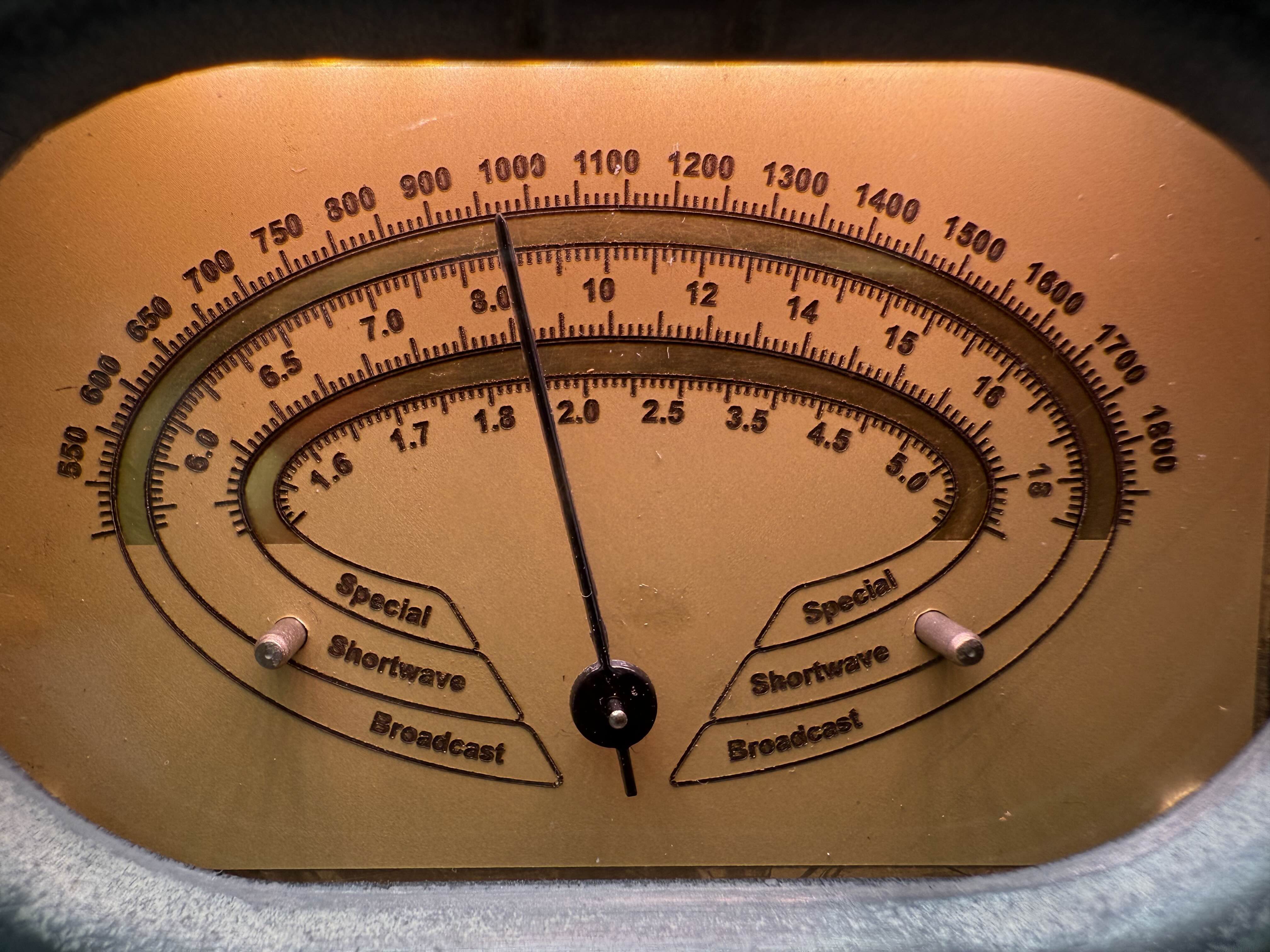
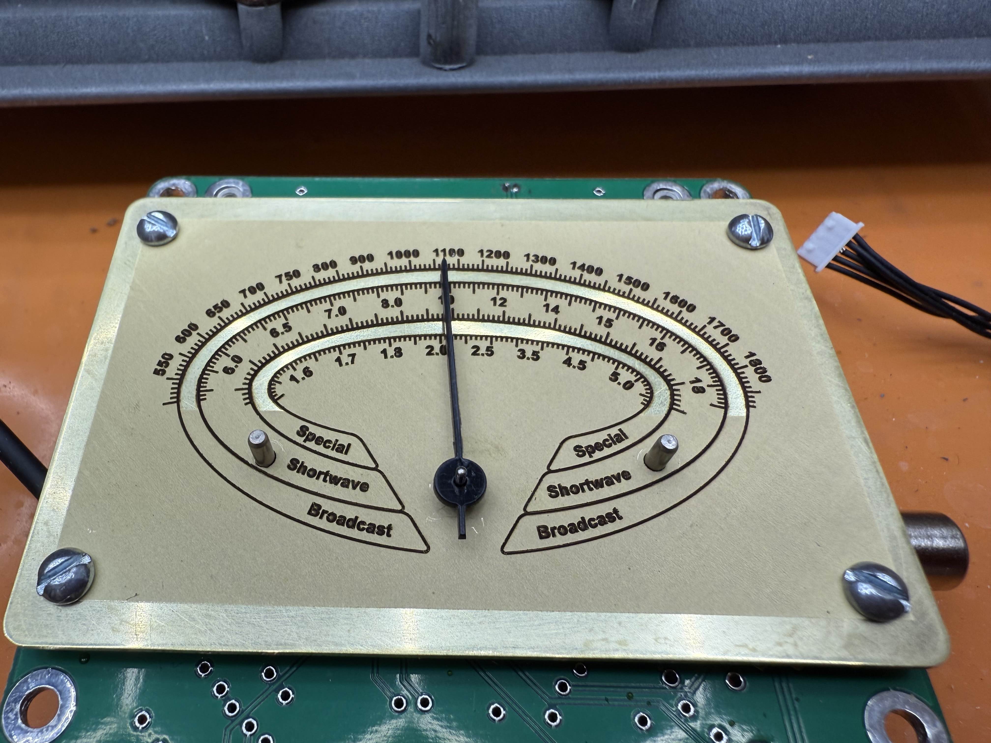
The software is adaptable for different radio gauges, using settings to set the amount of dial movement, and automatic distribution of the stations across the dial.

It even has 1950's mechanical ultra-sonic remote control support using a 80KHz capable PDM microphone and FFT code.

The to do list :

  • Finalize schematic
  • Design and prototype the PCB
  • Get mechanical ultrasonic remote working with audio/background noise interference
  • Decide between water printed MDF, or real wood.
  • Wood work the enclosure (CNC, or handmade TBD)
  • Acid etch brass plates (Reviving a dual etching process to leave a mirrored area)
  • Test composite video output


Simulated live radio station method:

Each simulated radio station is made up of a dequeued list of audio files, along with the length of each song.

When the code is first started, the master start-time on each radio station begins.

As you tune across the dial, the code figures out which song should be playing, and what time in the song we should be, based on the amount of time that has past since the master start time.

For example, if 15 minutes have elapsed since the master start time, then the code will subtract the length of each song in the list from the elapsed time, and at the same time move that song to the end of the list.

Once the amount of remaining time is less than the length of the song at the top of the list, then the code drops into that song, at the point in time remaining in the calculation. 

The radio stations loop automatically. They can also be dynamically randomized, skipped/rewound or otherwise altered in time without losing the live playback effects.

Radio Station Tuning Method:

To allow for flexible tuning regardless of the number of stations, or the size of the radio dial, a feedback loop is used to determine what radio station to play, or whether to play static, or no station at all.

On the Pi Pico a tuning potentiometer controls the angle of the motor, linearly from the minimum angle to the maximum angle. This gives a good 1:1 feel of the tuning knob, versus the movement of the needle.

The code on the Pi Zero then monitors the motor/needle angle, and determines the nearest radio station to that angle. If the needle starts to move near the position of a radio station, it starts playback of that station, at a low volume level, while still playing static. As the user tunes closer to the station position, the volume raises, until the needle falls close enough to the station that it is considered "locked on", in which case the station plays at full volume with no static.

The area of "lock-on", partial playback, and static only is automatically setup depending on the number of radio stations present on the dial, as well as the range of the dial.

Using PyGame for the music playback allows for very fast tuning as it can stream the file from disk without caching the whole file, as well as drop into a particular timecode. The tuning occurs so fast that sweeping across the dial and hearing small blips of audio works just like a analog AM/FM radio.

Air core motor control method:

At first I tried using a typical low cost stepper motor, but even with half-stepping the movement looked like a cheap watch, with very visible discrete steps for each movement.

I am now using a tiny Simco Air Core Motor. An air core motor is just a magnet attached to a shaft, with two coils would around it at perpendicular angles.

Setting the angle of the motor is a matter of controlling the SIN and COS coil voltages. This results in very smooth analog movement of the motor The challenge came when trying to find a dual H-Bridge motor controller to use. A normal dual PWM controller has issues when the coil is near any of the angle quadrants (0, 90, 180, 270 degrees). As the voltage on one of the two coils will drop to nearly zero.

The solution was to use a TB6612 dual H-bridge controller. This controller has separate digital inputs that control the direction of the motor, and a separate PWM input for each motor. This allows the voltage to remain near constant across the coils, and the duty cycle changes with the PWM input.

  • Faceplate

    zapwizard2 days ago 0 comments

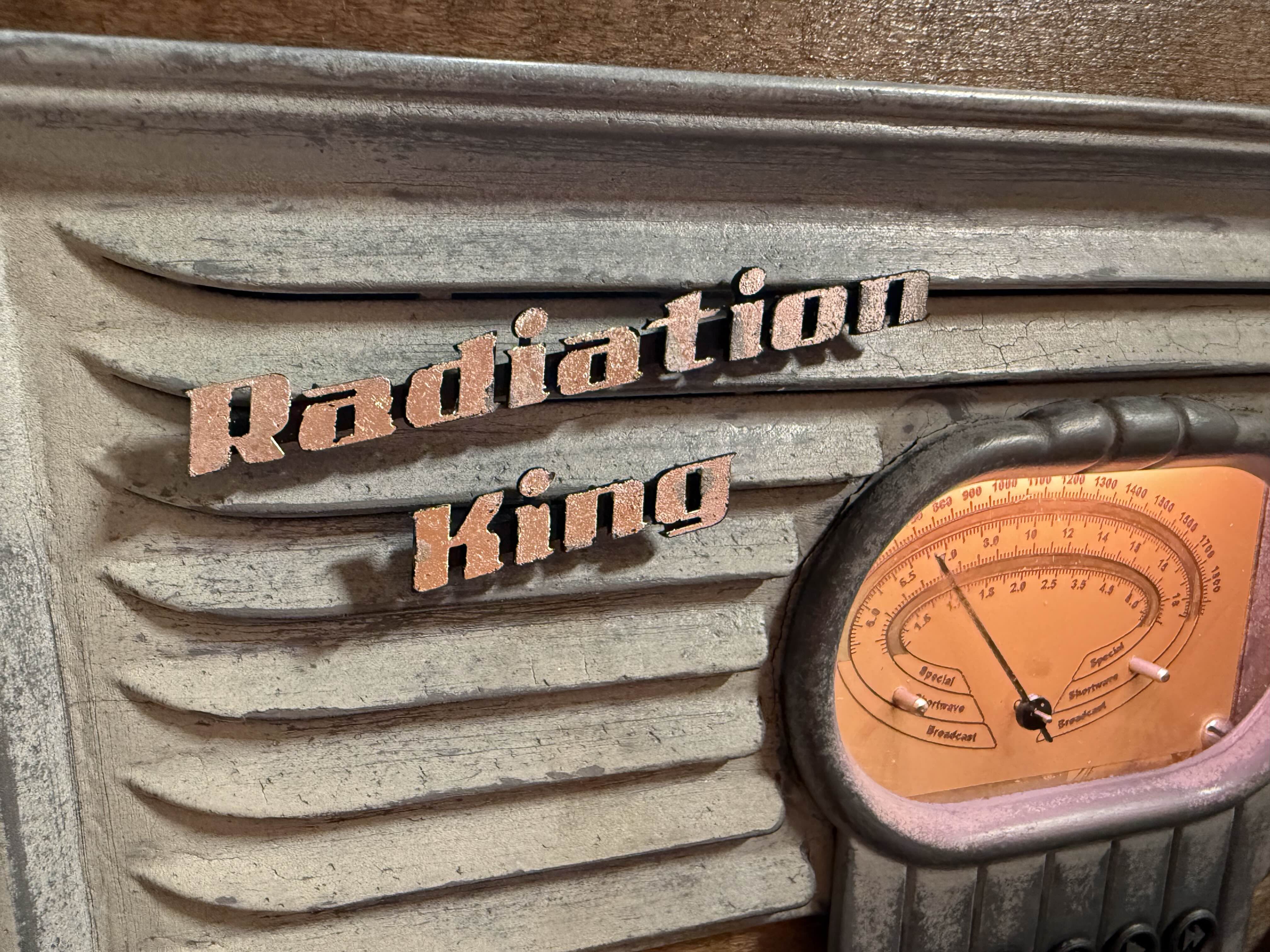
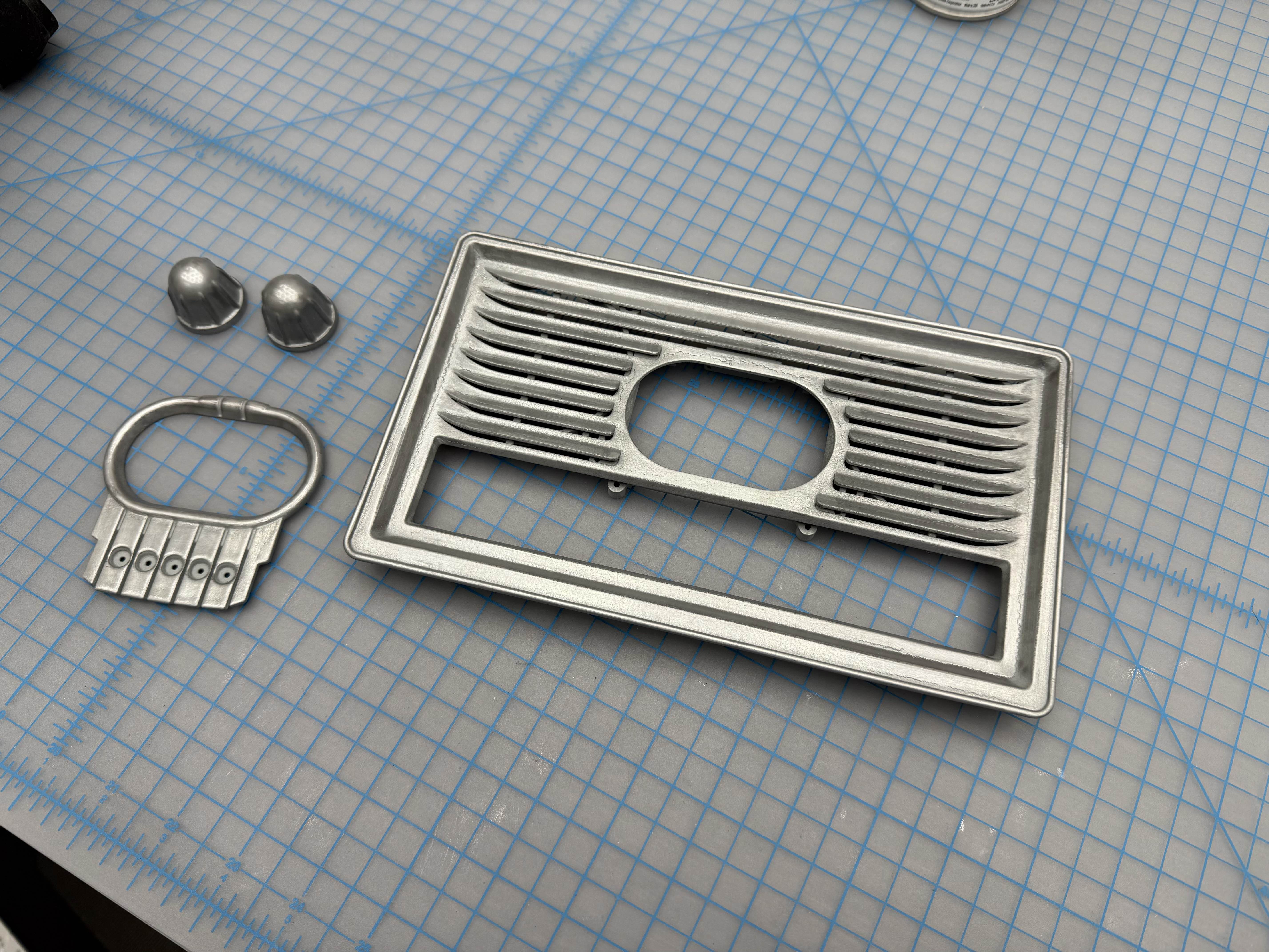
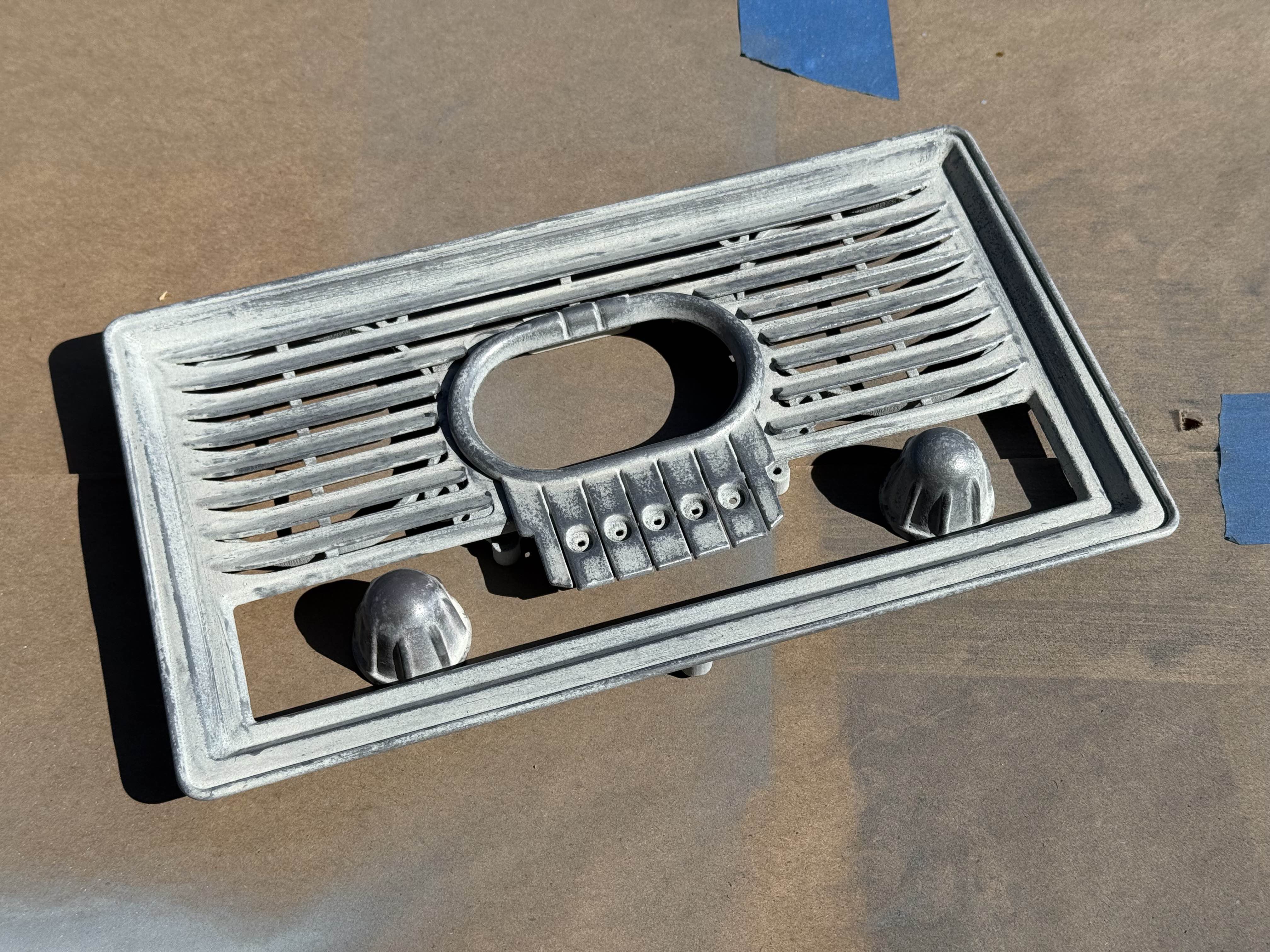
    I wanted the front bezel to look like metal. So I used a technique I saw somewhere on the RPF: Zinc Galvanizing Spray. 


    This is a paint with lots of zinc metal in the paint. It goes on grey, but then can be shined up using steel wool.
    However, after polishing the whole face, it did look like metal, but also very boring and monotone.


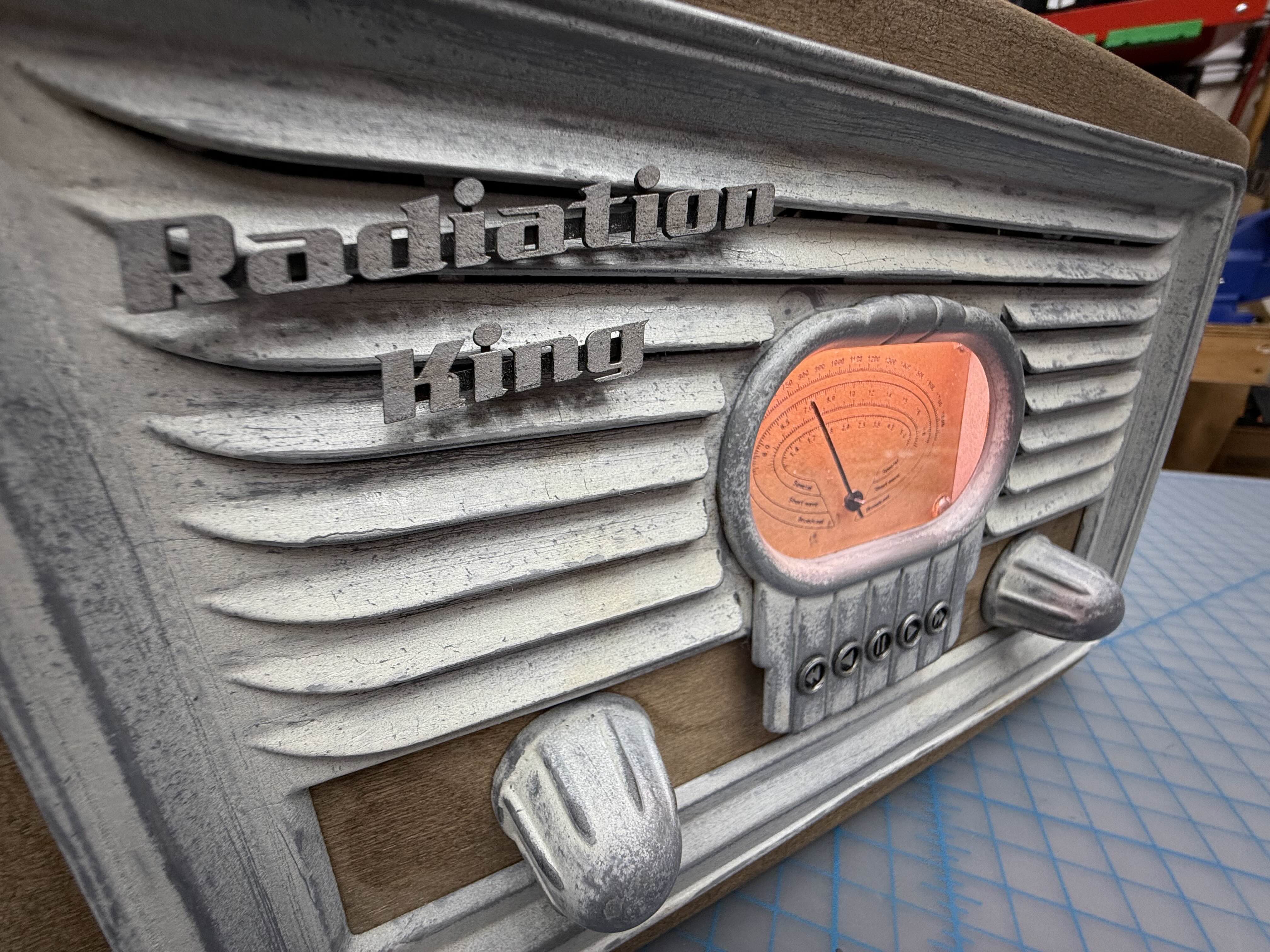
    I had purchased some cream colored paint to try as an alternative, but then had an idea: Use both!
    I sprayed a very light coat of the cream colored paint over the zinc. I then polished away the paint. It really looks very nice in person. The zinc shows up as glints of metal, and the paint makes it look like the radio has been around for a hundred years. The coolest part is any more wear over time will just make it look more authentic. Later I added some washes to break up the two color finish with a bit of very light rust.


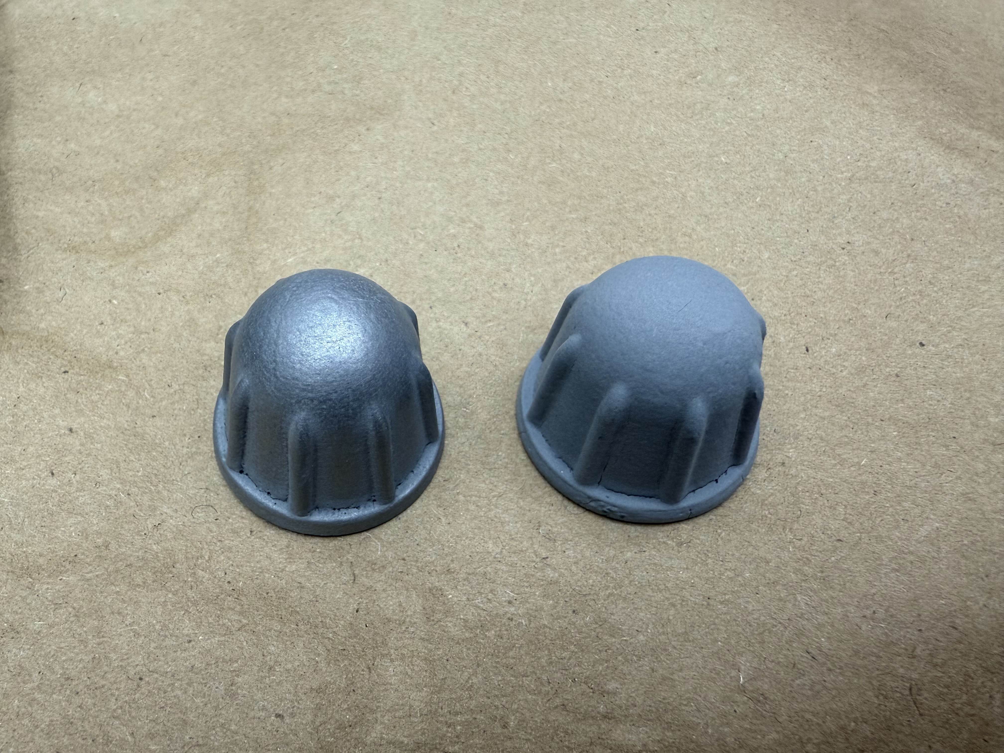
    I SLA 3D printed the logo, and small buttons. Then used a molotow chrome pen to make them silver, aging them similarly.


    I did another test assembly of the radio, and it looks (and sounds) like it was taken right out of the game.


    There are still a few more things to do. The gauge is currently paper, and it needs to be replaced with laser etched brass.
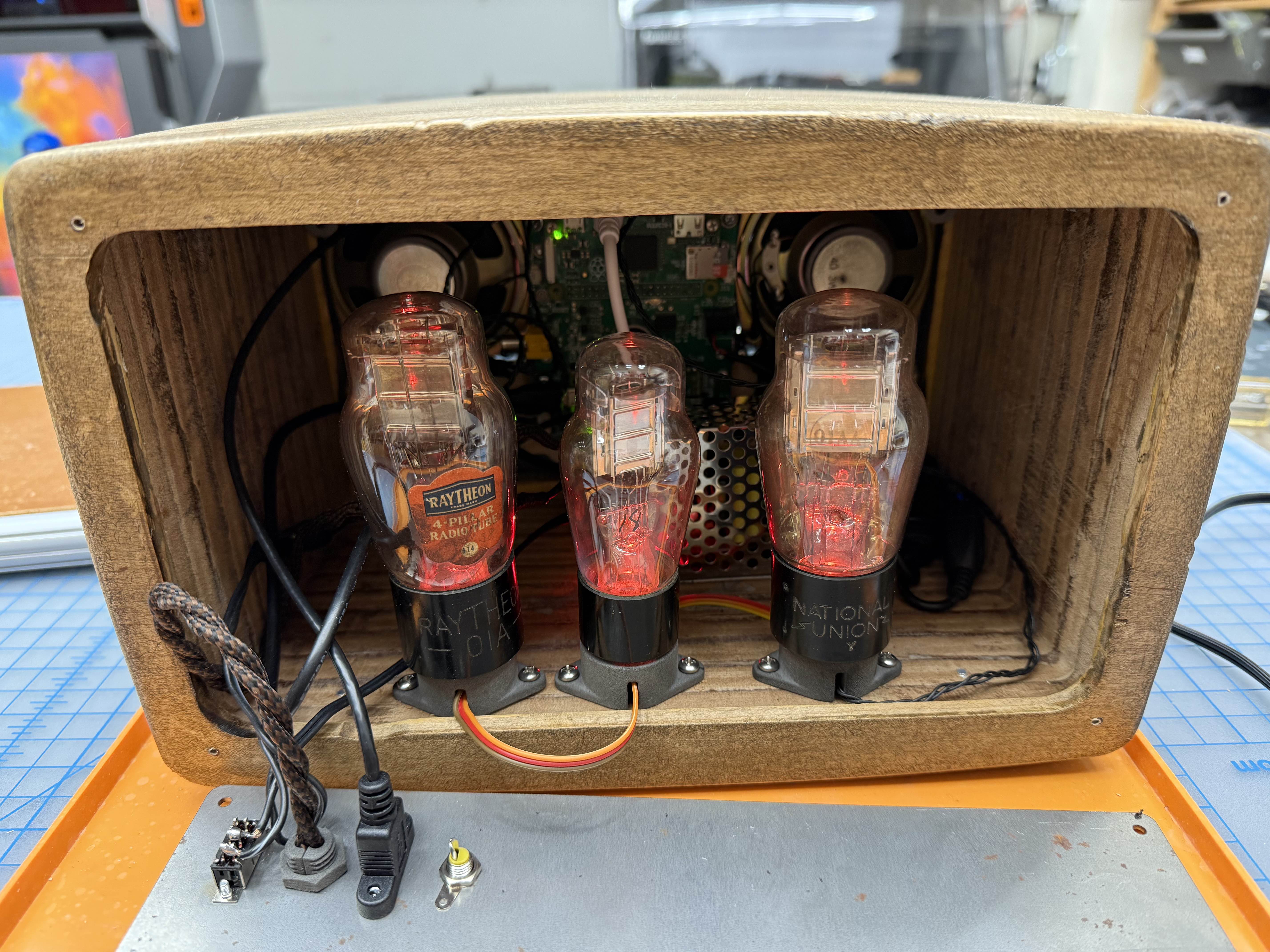
    I have some fake vacuum tubes to add to the interior, along with LEDs to illuminate them.
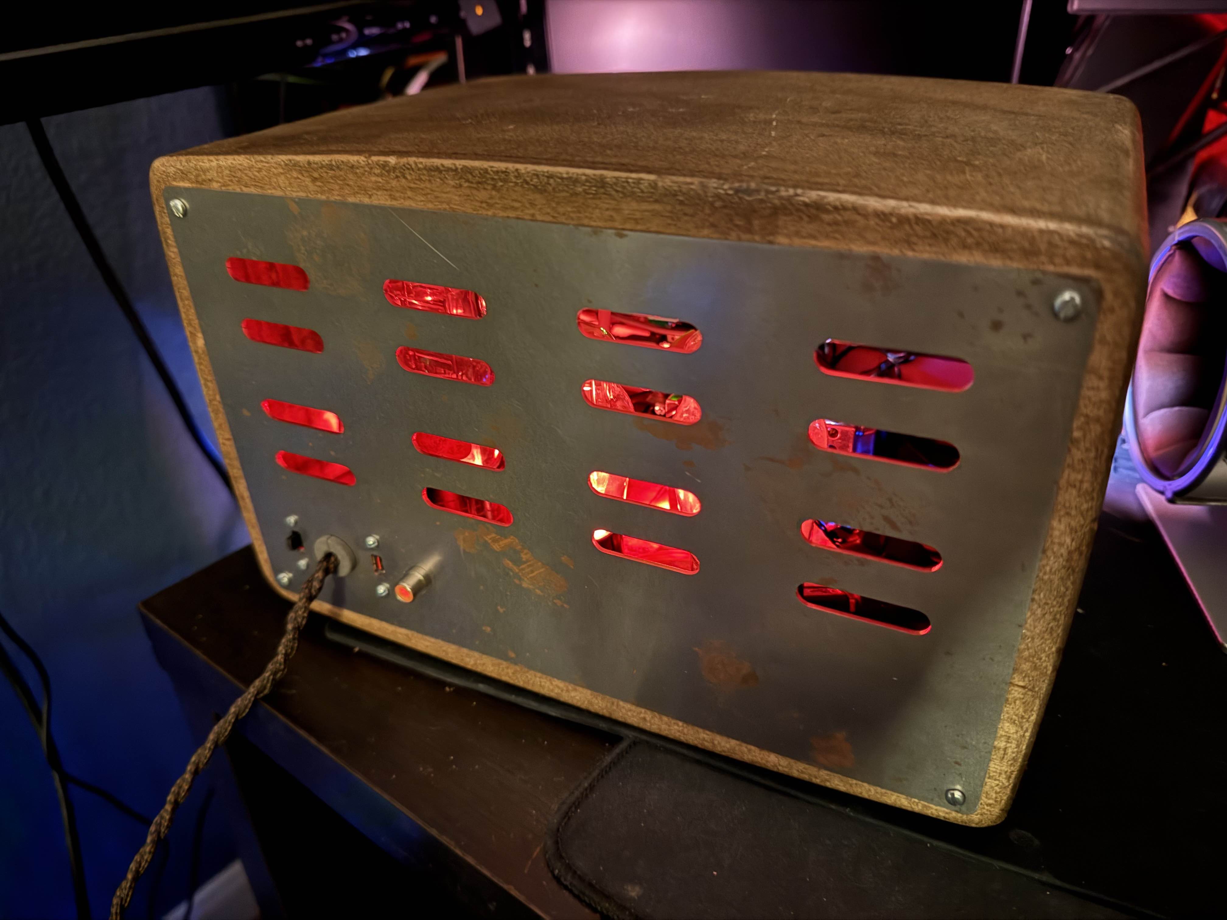
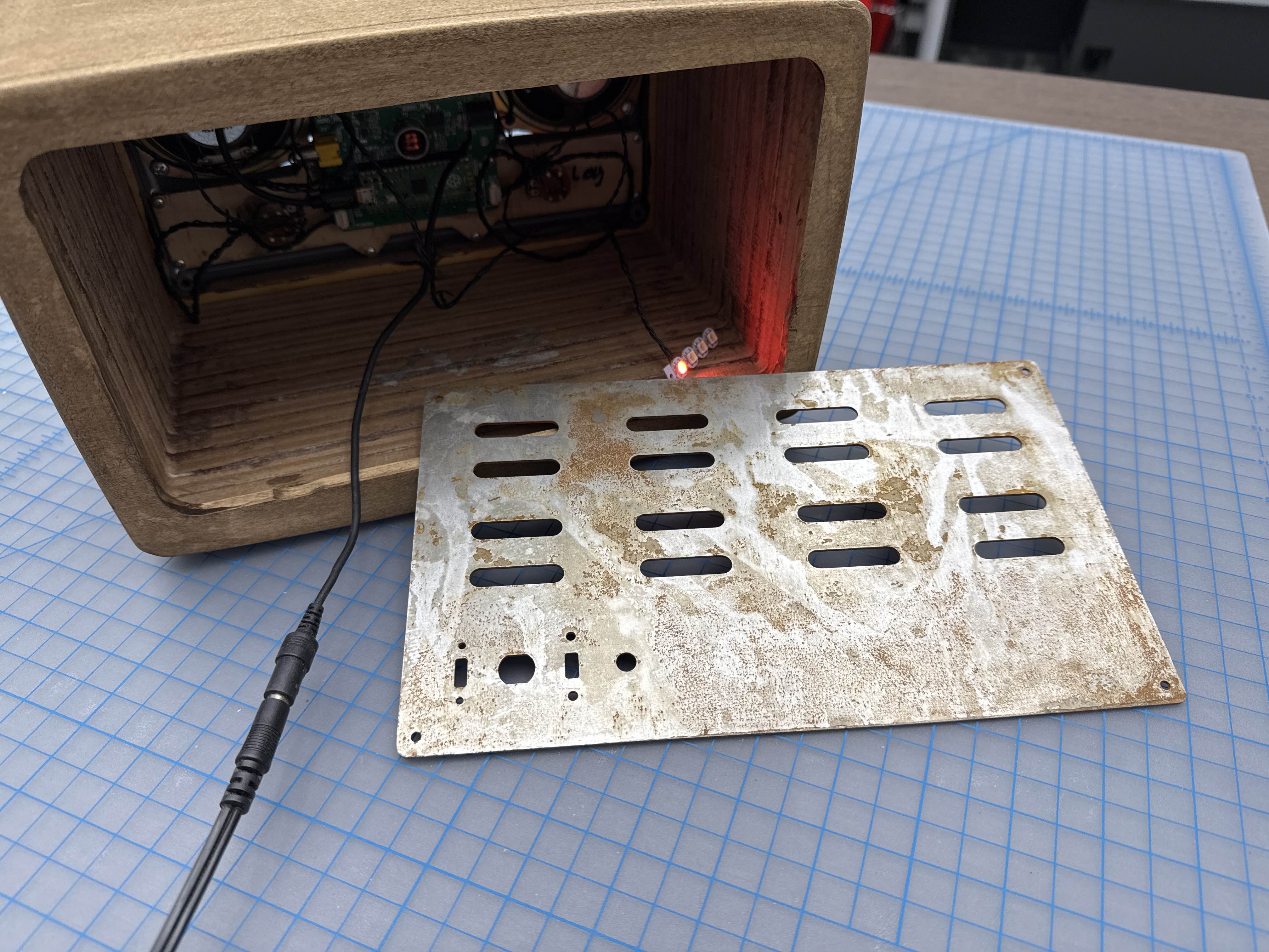
    Then everything gets wired to the rear panel, which has authentic rust on the steel plate.

    I have a few electronic bugs to work out. The major one being that the Pi Pico doesn't want to show up on the Raspberry Pi at a fresh boot. I have to physically remove the Pico from the PCB, reset it, and then plug it back into the board with USB still attached.

  • Woodworking

    zapwizard2 days ago 0 comments


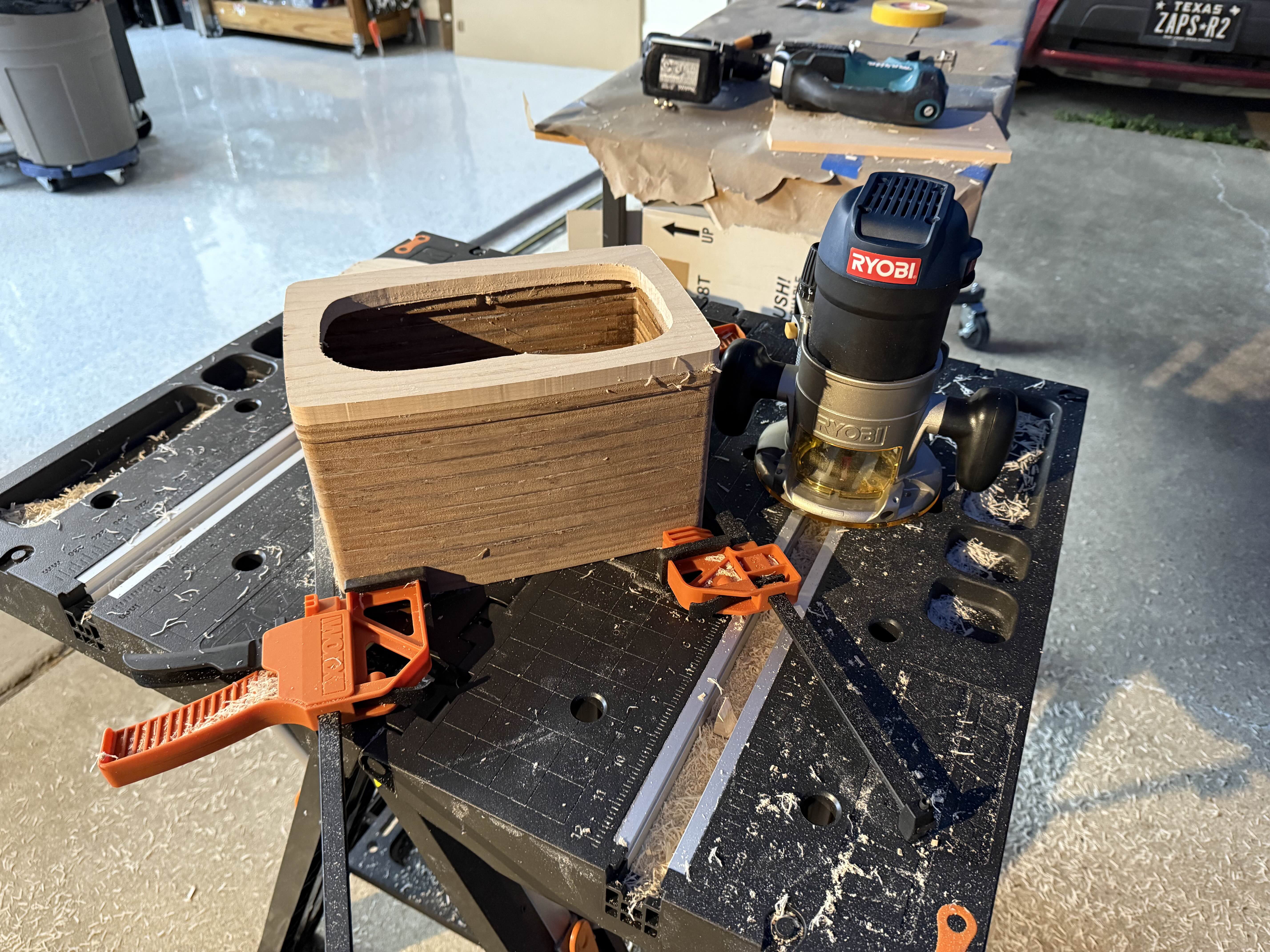
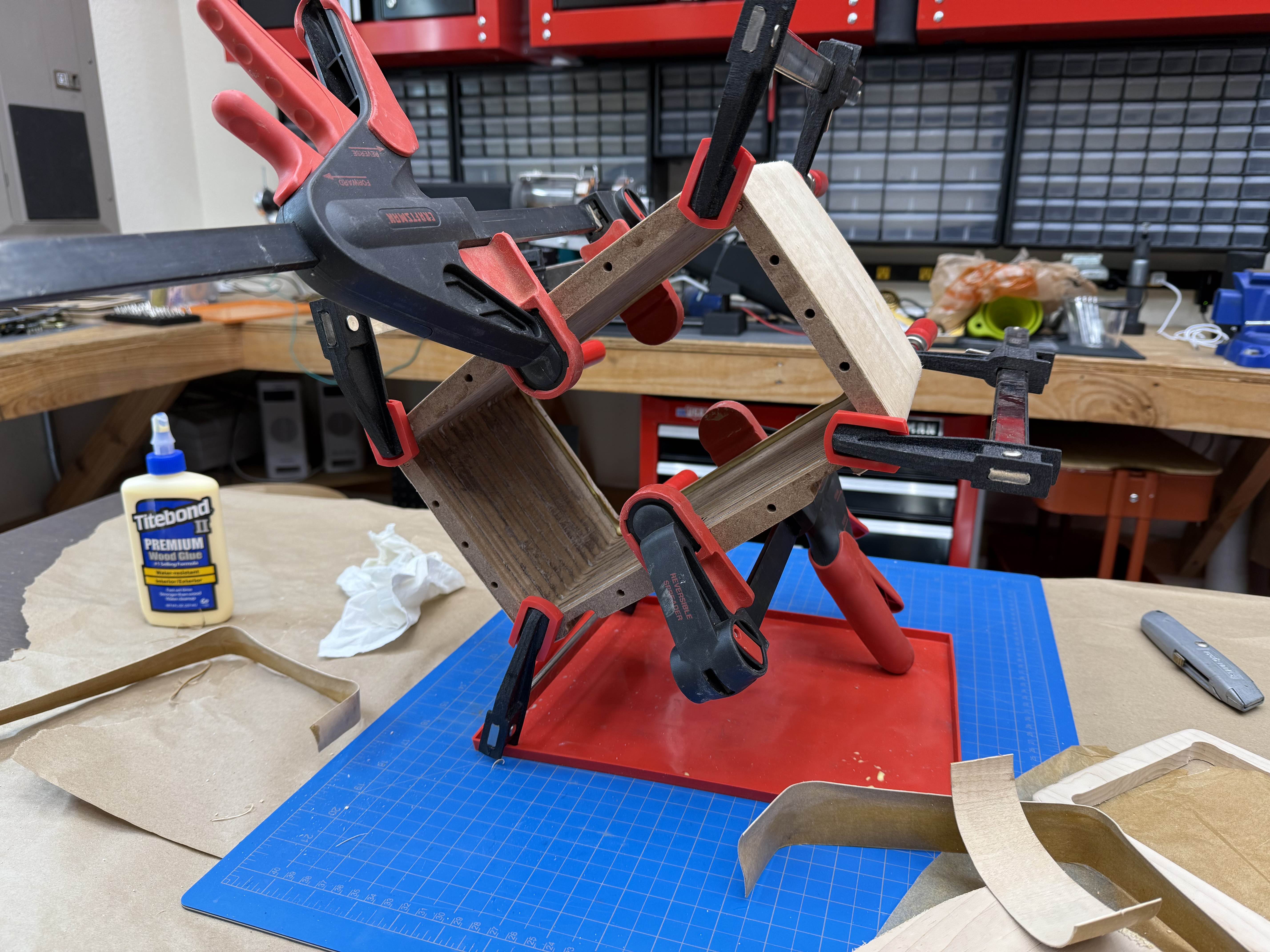
    So I had some motivation this weekend and got a whole lot done on the radio. First I glued up my 12 layers of MDF. The 12 layer was supposed to be a routing template for the front panel, but I accidently included it in the stack. I used a trim router bit to carve the 1/2" thick maple front, and then the 1/4" maple back panel.


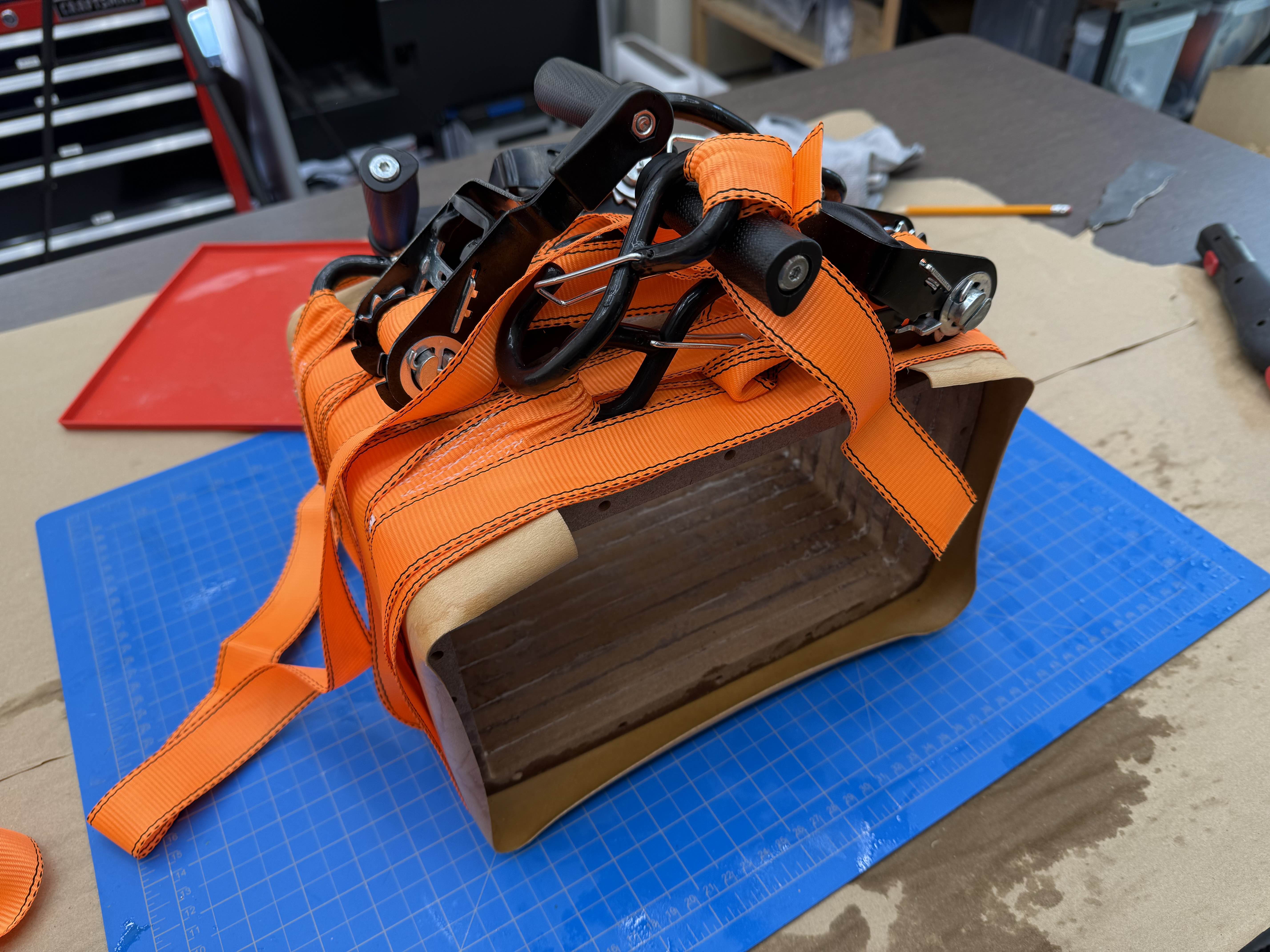
    To cover the MDF, I am using 1mm thick maple veneer. Before I glue it though, I pre-formed it to the MDF by steaming the wood and then wrapping it with ratchet straps.


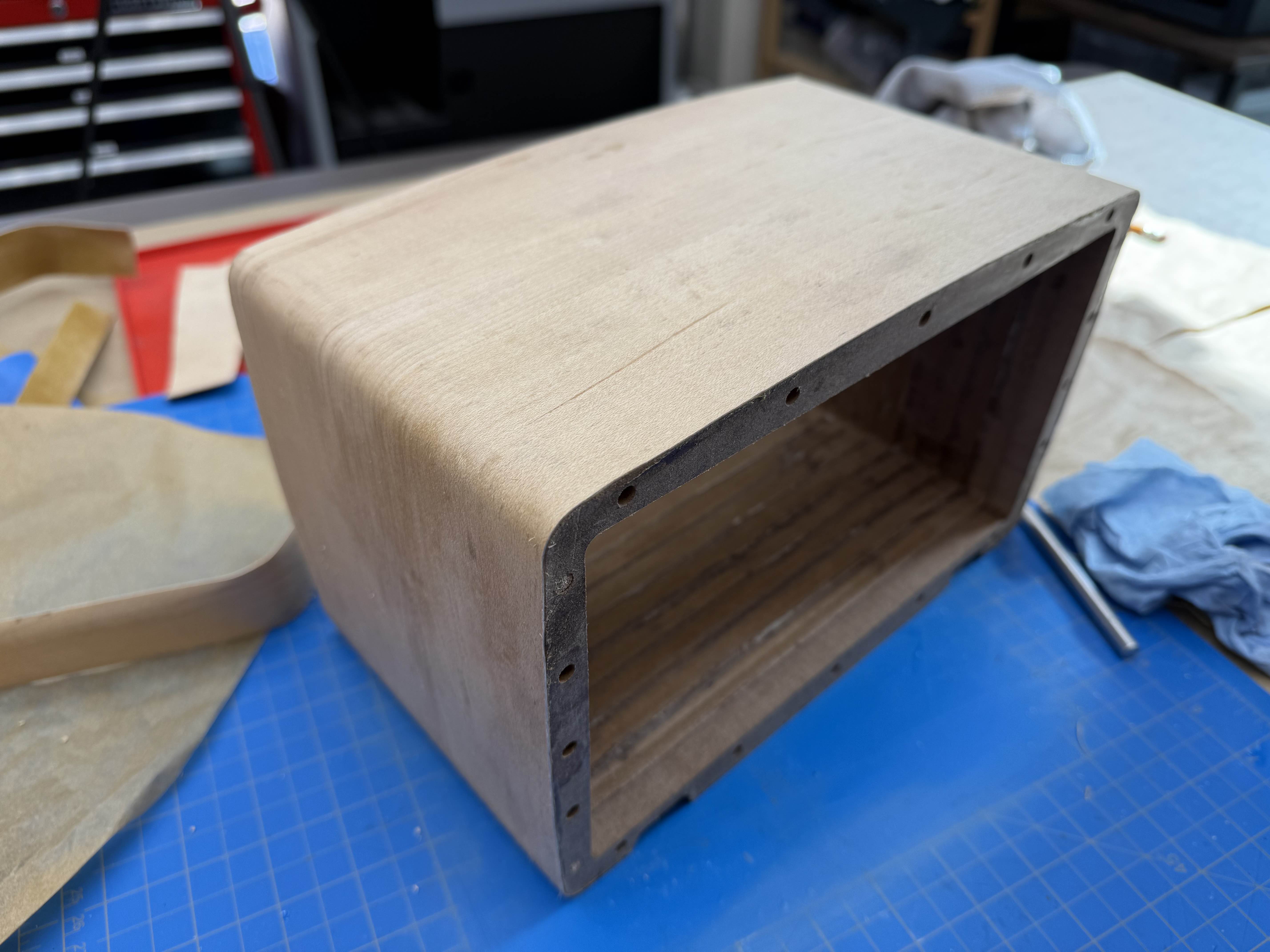
    I then used contact adhesive to bond the veneer to the MDF, and trimmed the excess.


    I glued on the front and rear maple panels. Later I applied a rustic wood stain to the whole thing.

  • Boards from PCBway

    zapwizard09/22/2022 at 14:36 0 comments

    IMG_20220818_101901.jpg

    My circuit boards have arrived!

    I have to give a special thinks to PCBWay for these. They gave me a good discount on getting these boards made, and they even sourced and populated the SMT parts for me. They even were able to get the motor driver IC that is out of stock at all the US suppliers.
    All I need to do is add the though-hole components. They were so far, I am actually still waiting on some of the parts to arrive before I build up the board.

    The board itself is four layers, with more time and a less symmetrical layout I could probably get it down to two layers. I designed it in CircuitMaker. You can get the design file here.

    --------------------------------------

    Exploded Layers.jpg


    So I decided on a method for my enclosure construction. I wanted something that didn't require me to sand the whole curve into the enclosure, and I wanted something that folks to reproduce. I debated trying to use a wood CNC, but most of the software I could find did inaccurate 2 .5D etching, or charge huge amounts for true 3D sculpting.

    What I ended up settling on was to use lots of layers of laser-cut plywood with dowels to make the main structure. This section will be covered with a thin real wood veneer.

    The front will be made from 1/2" of maple, and the back will be a 1/4" piece of maple., both with rounded edges.

    -----------------------

    IMG_1074.jpg


    It took a few hours to glue up the 45+ layers together. If I were to do it again I would use 6mm (1/4") plywood to save on the total number of layers.


    -------------------

    IMG_1097.jpg


    I then waited 24 hours to the glue to fully cure. I used a belt sander to remove all the glue and the laser burnt edges. I then slathered the surface in wood filler (I smoothed and removed most of it after taking this photo)

    Once that fully sets I will sand and paint the surface with a filler primer. This will then become the base that gets wrapped with the veneer.

  • Video logs

    zapwizard02/14/2022 at 19:53 0 comments

View all 4 project logs

Enjoy this project?

Share

Discussions

Similar Projects

Does this project spark your interest?

Become a member to follow this project and never miss any updates