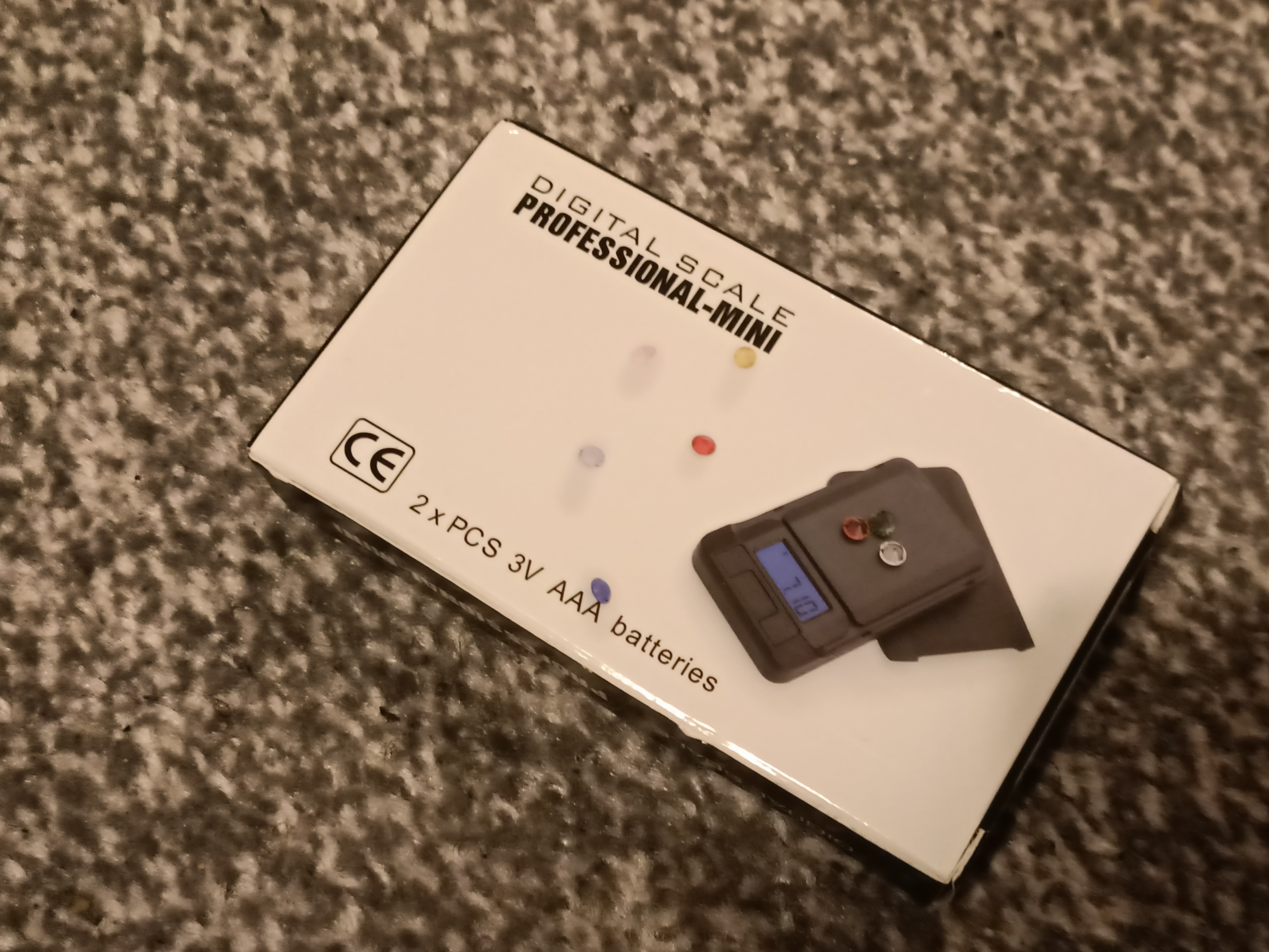
 As mentioned in a previous log (I think), it's cheaper to buy an entire mini scale than to buy the 300g or 750g load cell by itself. First I took the AAAs out of my 2Kg scale to test it and it indeed works:
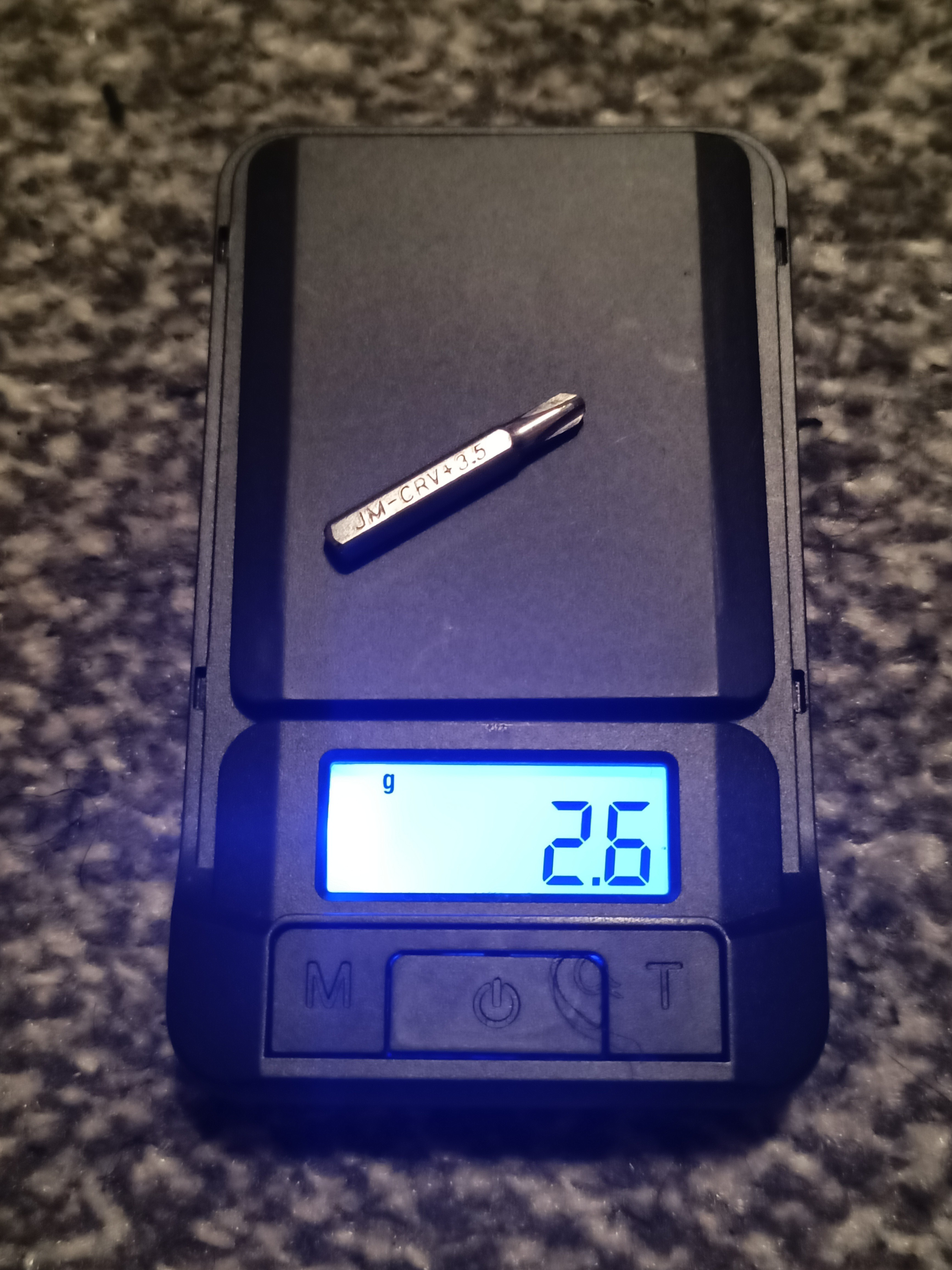
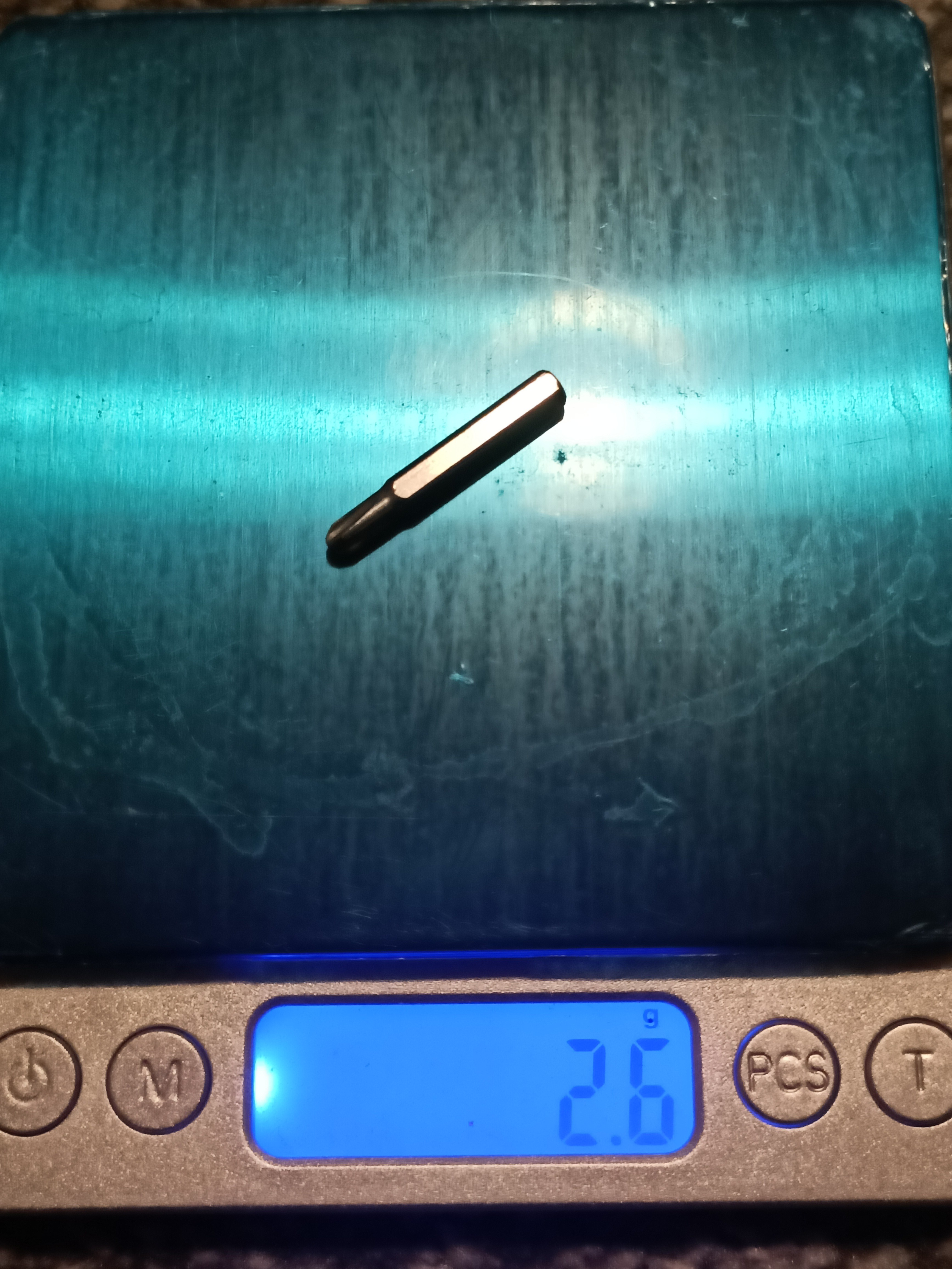 Both scales agree on the same weight. Suprisingly, the cheaper scale looks to have a higher contrast LCD.
Well time to open it.
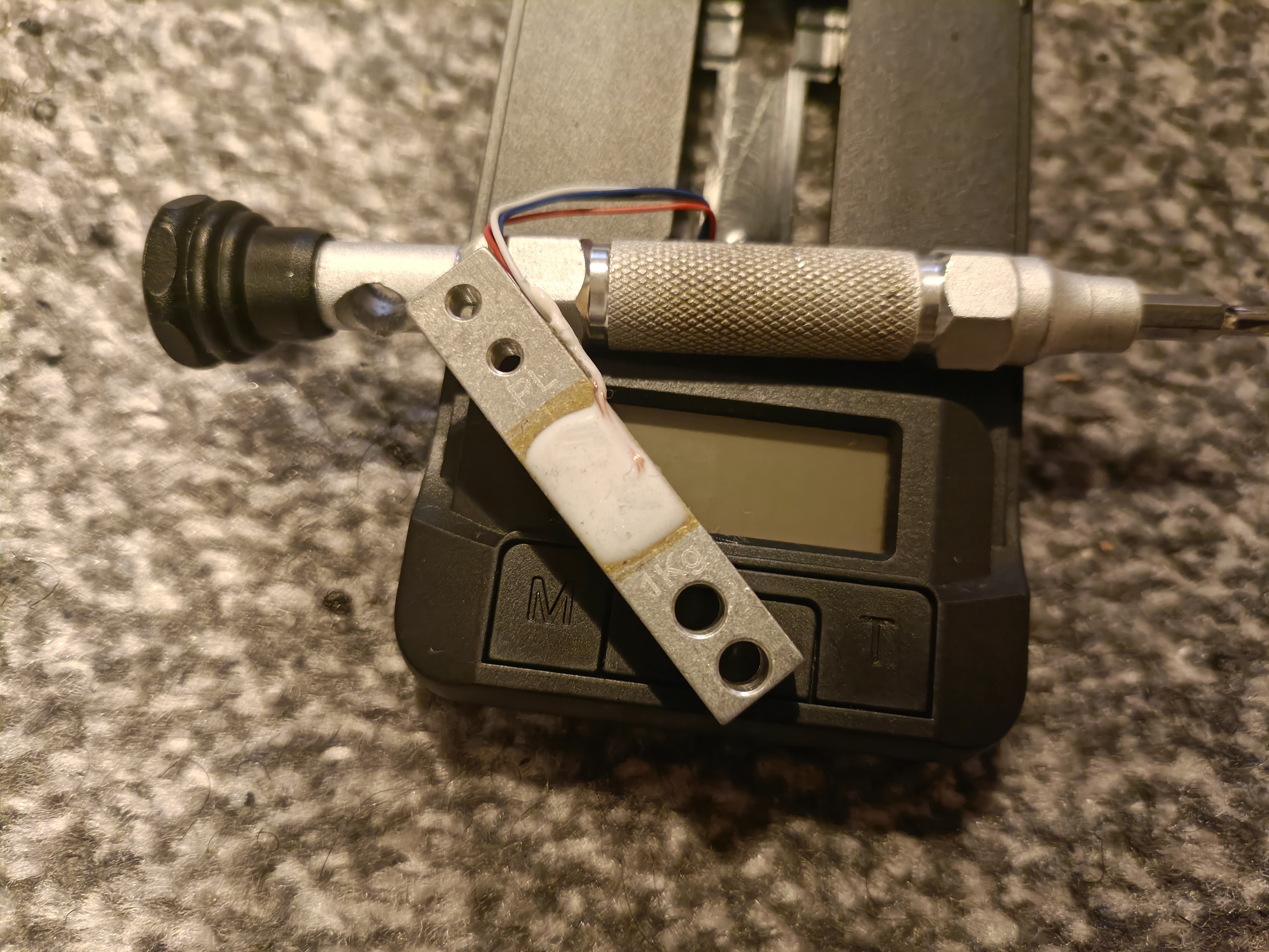 8 phillips head screws later and I got to the load cell, which seems to actually be rated for 1kg and has 2 4.15mm holes instead of M3 threads. Looking at the inside geometry, it seems that they used to be M3 threads and drilled out. The scale plate has 4.10mm stems that friction fit though and held in place by self tapping screws.
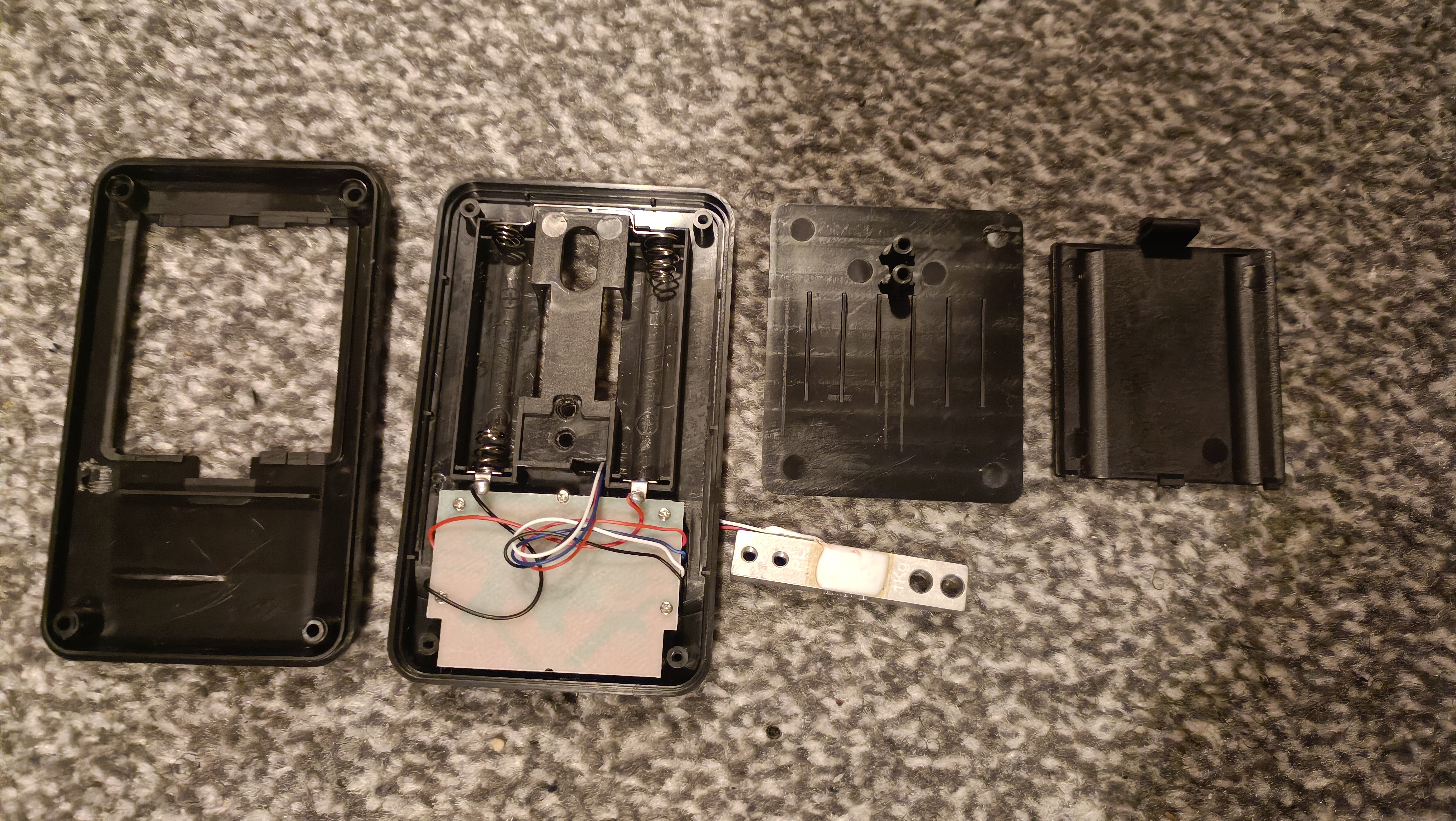 Another 5 small phillips screws later, and I can see the board:
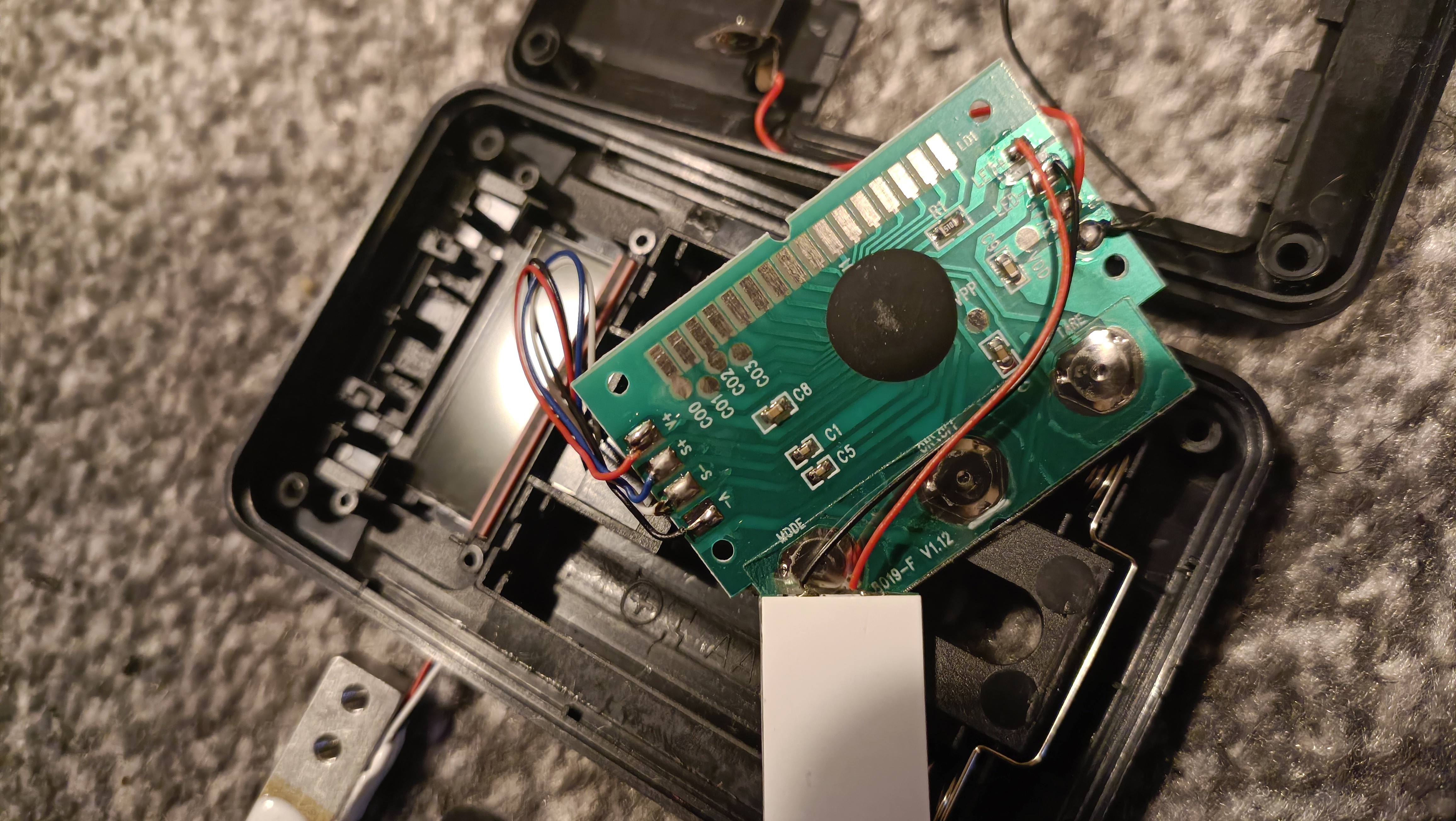
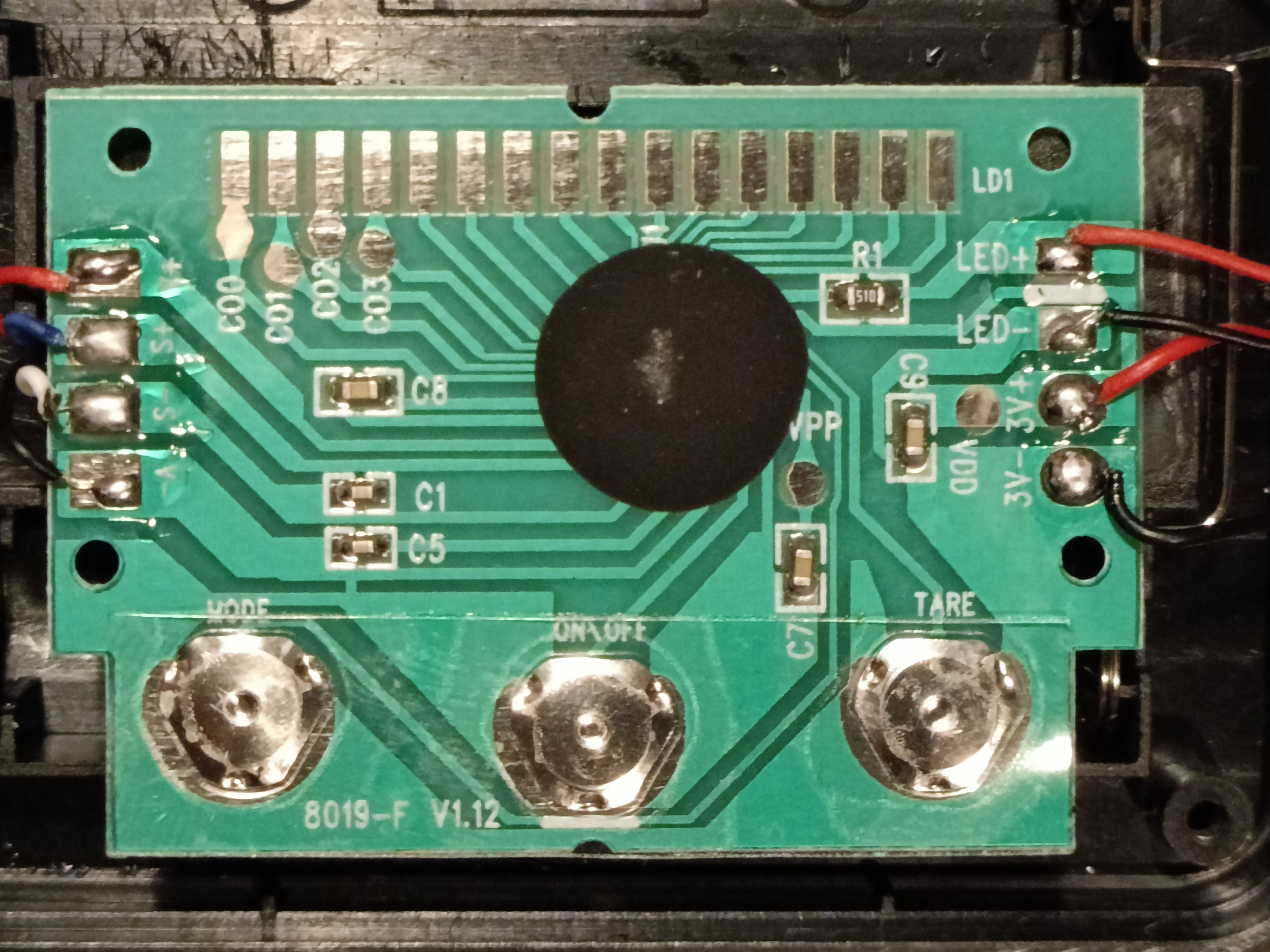
The S+ and S- have a small C1 capacitor inbetween them, so I probably should also add that into my PCB design since a £1.50 scale is probably cutting as many corners as it can (thus, if the cap wasn't needed, it would have been ommited). As expected, the LCD contacts the board via pads. While transparent, the LCD is quite a bit darker than just clear acrylic or something, likely to do with polarisation. Here's it infront of the glossy white box:
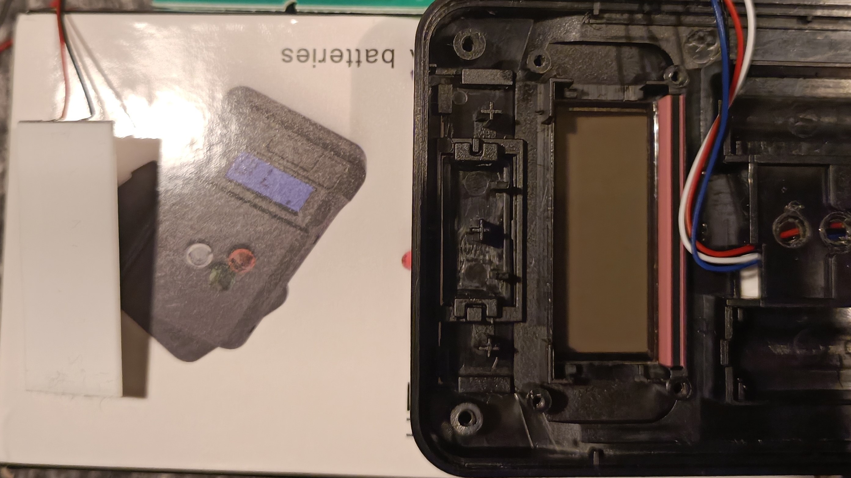
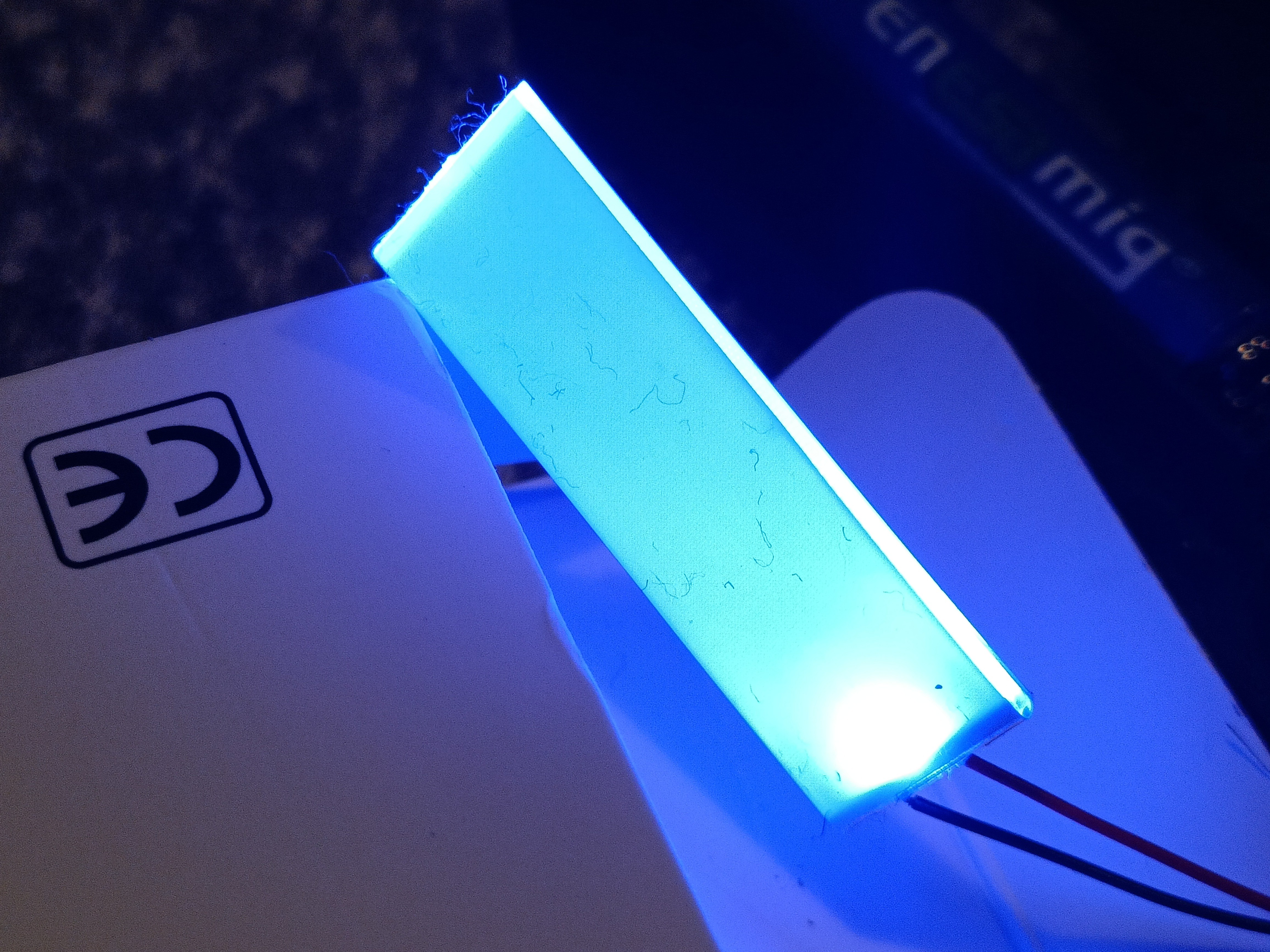
The LED doesn't magically look really bright though. I've put this next to the glossy white box so you can see the exposure level. The diffuser film (that's over the clear plastic) is quite the dust/lint magnet, but it easily wipes off.
 The LCD actually looks rather cool without a backlight:
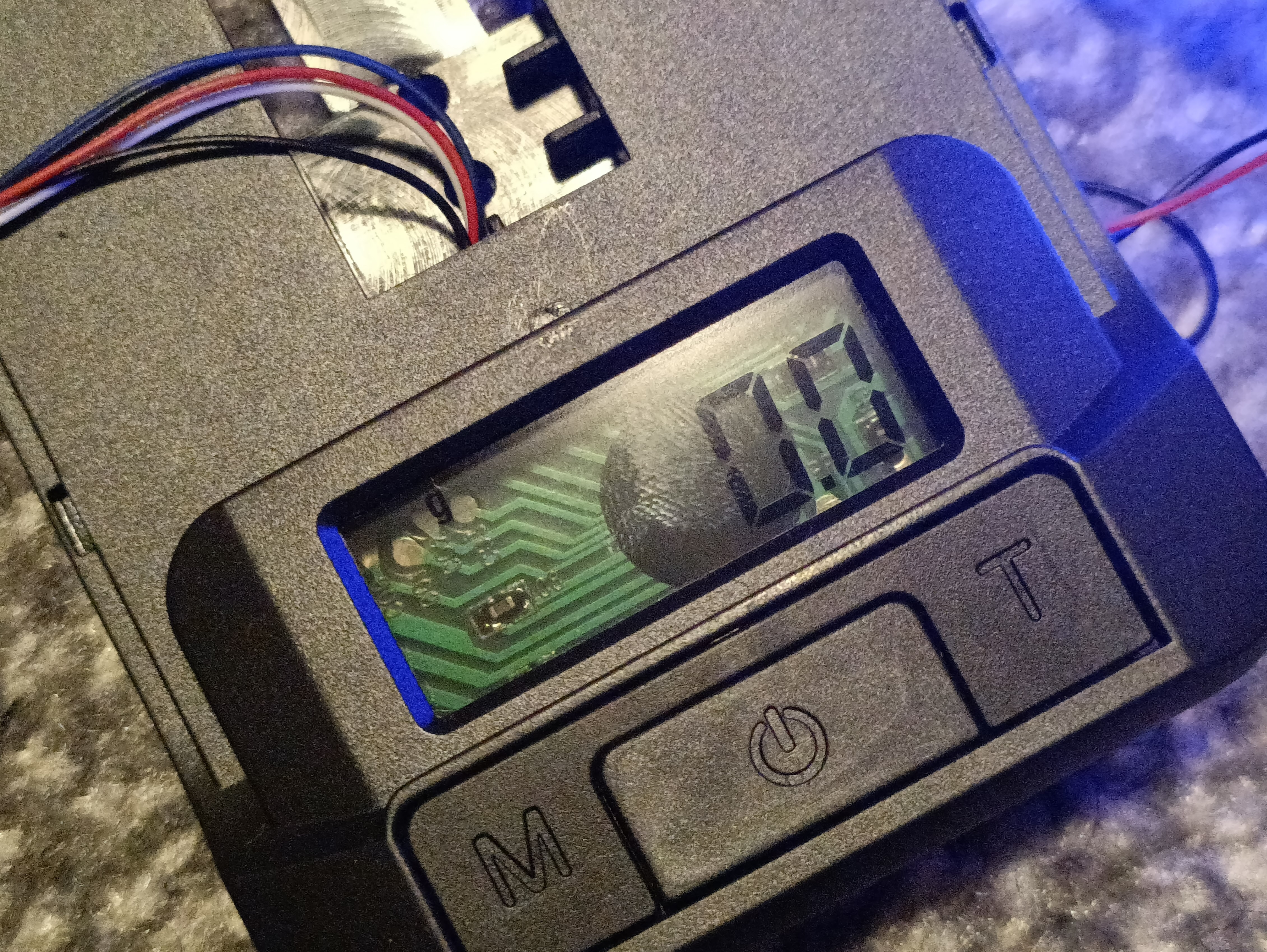 Not sure when I got a fingerprint in there but I didn't want to break the LCD trying to rub it off. The LCD now looks like it's got some cool, techy 3D background. It's like a hacker edition precision scale.
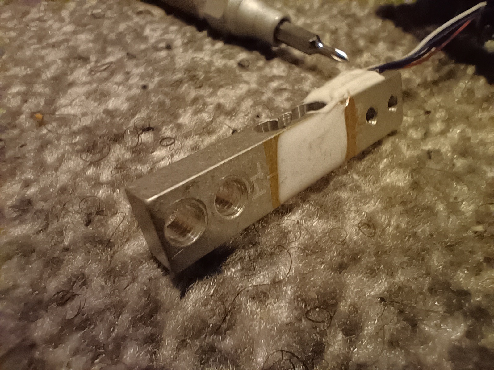 As you can see, there's a tiny trace of threads in the 4mm holes. It's kind of like Fusion360's textured threads IRL.
Anyway, the dimensions are still the same 6 x 9 x 45mm I hoped for. The thickest height is 7.3mm but I'd use 7.5mm in CAD. The wire relief on the side stops 4mm from the edge. Wires for V+, S+, S-, V- are red, blue, white and black respectively. Wire relief blob is an extra 1.6mm and the wires are 0.64mm diameter and around 10cm long.
 kelvinA
Discussions
Become a Hackaday.io Member
Create an account to leave a comment. Already have an account? Log In.