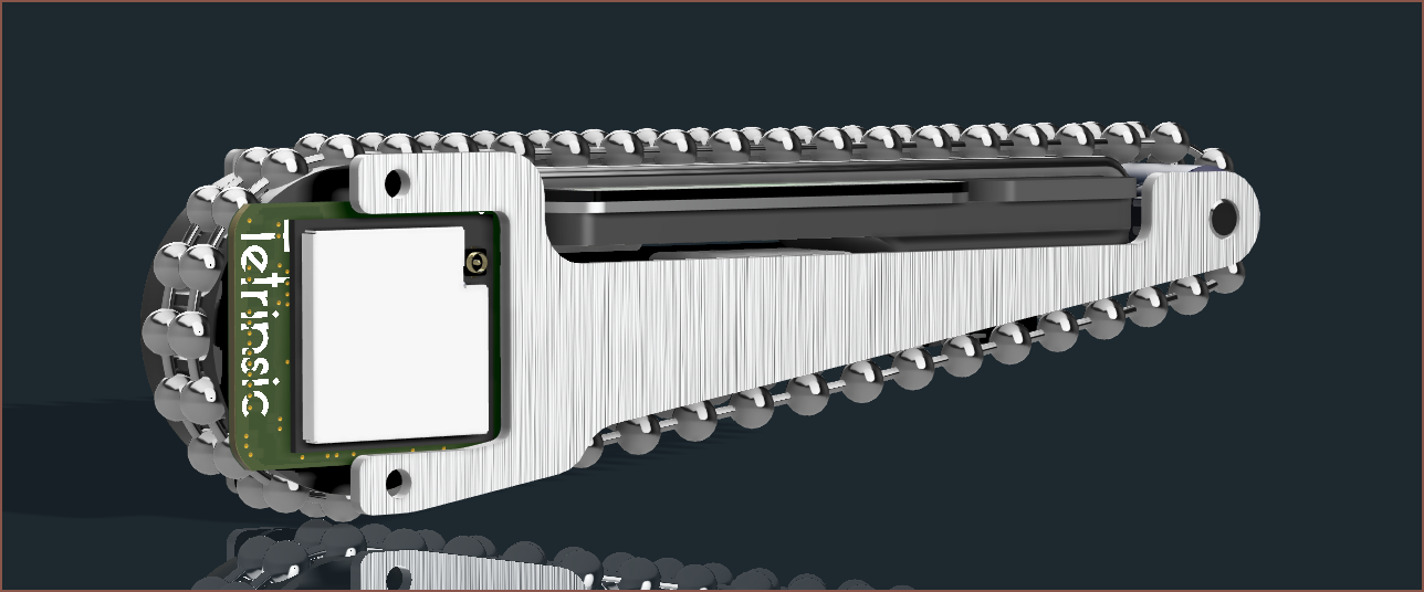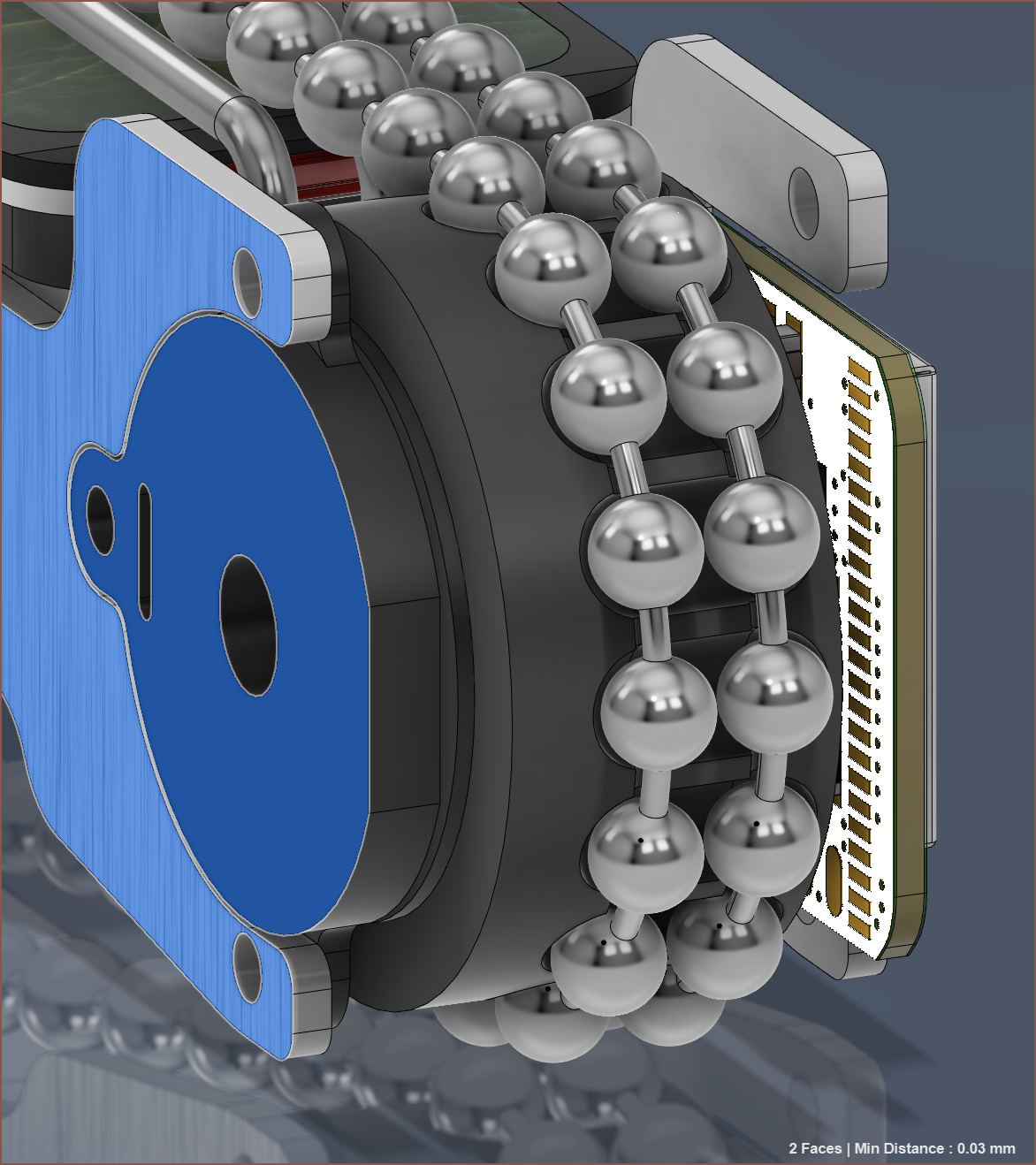
The idea I had was to generate a freeform model of the skeleton (see last log) and then see if it could be adapted to use JLCPCBs aluminium PCB service which comes in thicknesses of 1.0mm, 1.2mm and 1.6mm. As it turns out, the distance between the bottom of the motor and it's mysterious tabs is 1.17mm so I can use the 1.2mm option:

I'm not exactly sure what the motor tabs are for, but I'm going to try and use them with 2mm dowels. This would also be what I use to position the PCB. I'm also imagining printed parts with dowels to position them and lastly glue the whole thing together. Due to space constraints, there's not really any space to use bolts.
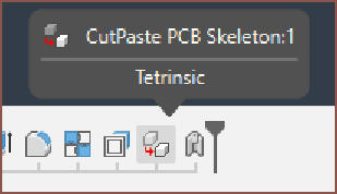
In unrelated news, I seemingly accidentally made the new component outside of the Tetrinsic component.

Yes, sure, I can and have just moved it in but I'm very tempted to just remake it. I need to tweak how I've done the skeleton anyway, since it'll still be much cheaper. I still haven't fully figured out how I'm mounting Tetrinsic to Tetent.
 kelvinA
Discussions
Become a Hackaday.io Member
Create an account to leave a comment. Already have an account? Log In.