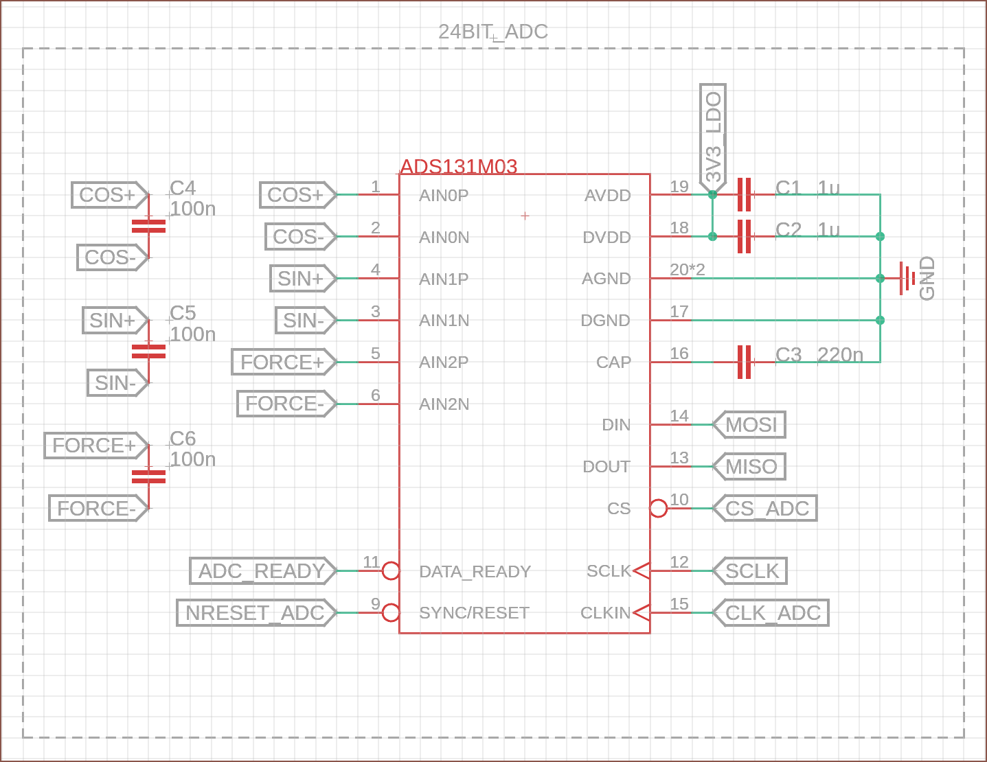
Fuelled off the good vibes of the Simcity 2013 soundtrack, I've ported over the circuit from my EasyEDA schematic that relates to the ADC:
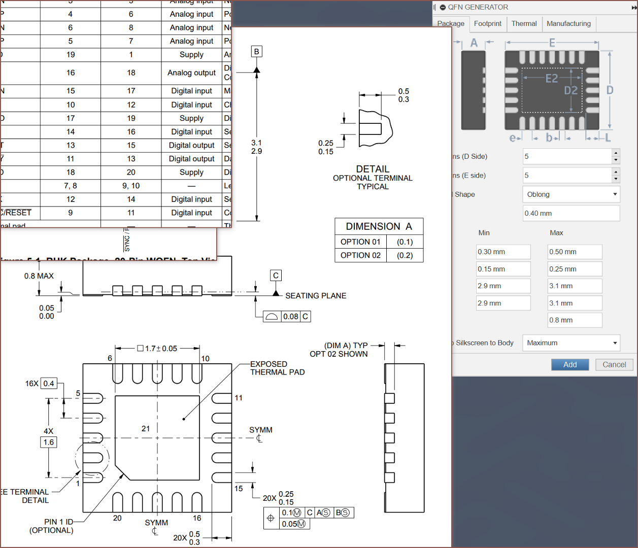
The first thing that I did was create the 3D model using the wizard, which also creates a PCB footprint along with it.
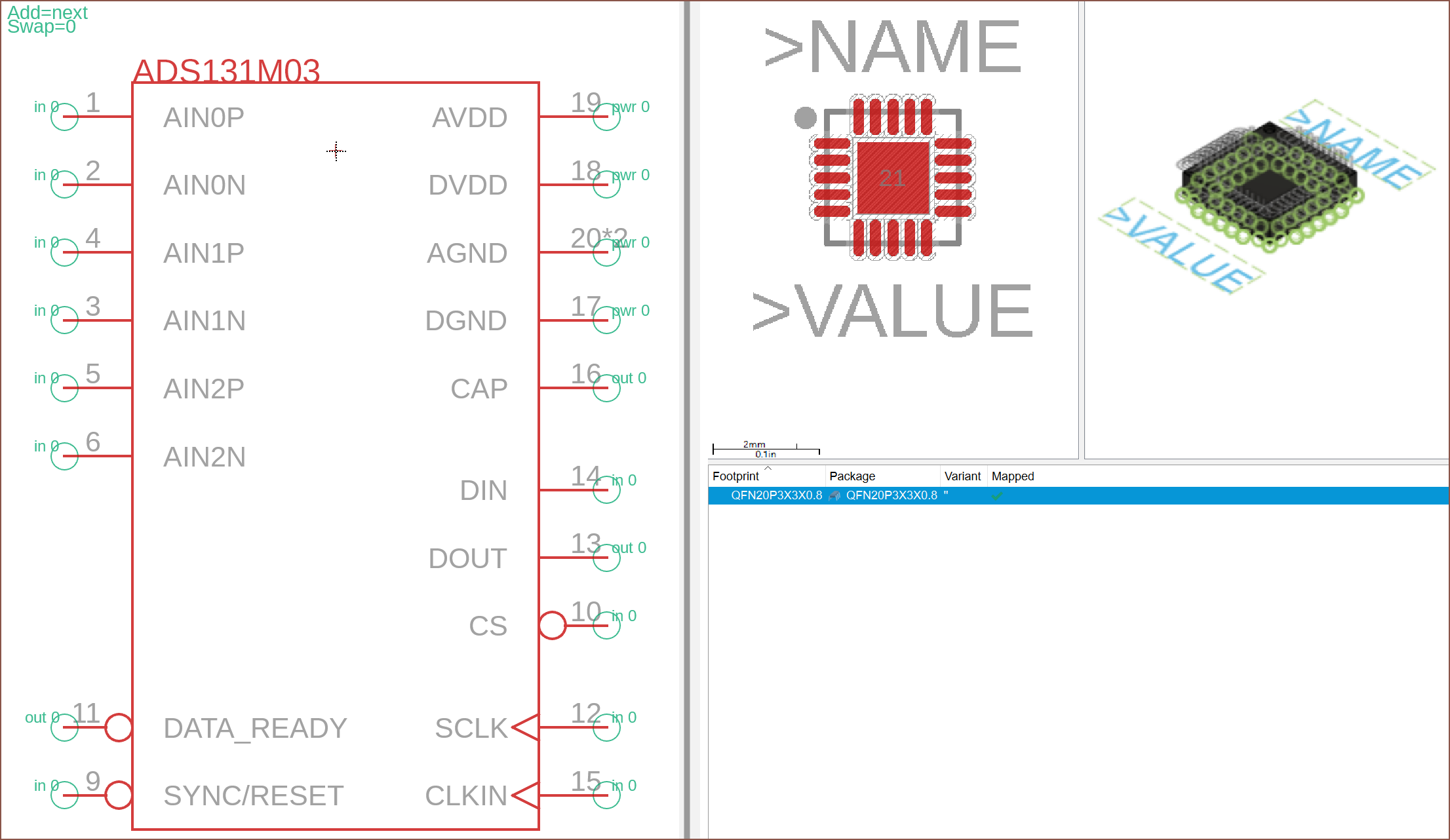
As you can also see, I increased the spacing of the pins. This is because it's needlessly time consuming to fix the formatting of components added to the pins because those small +'s overlap with everything:
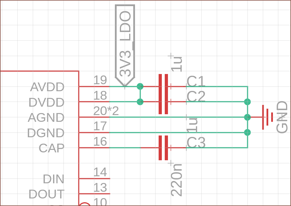
Speaking of the +, I've moved the IC symbol's one closer to the top so that I don't have to figure out the perfect center for every IC, especially as they get longer.
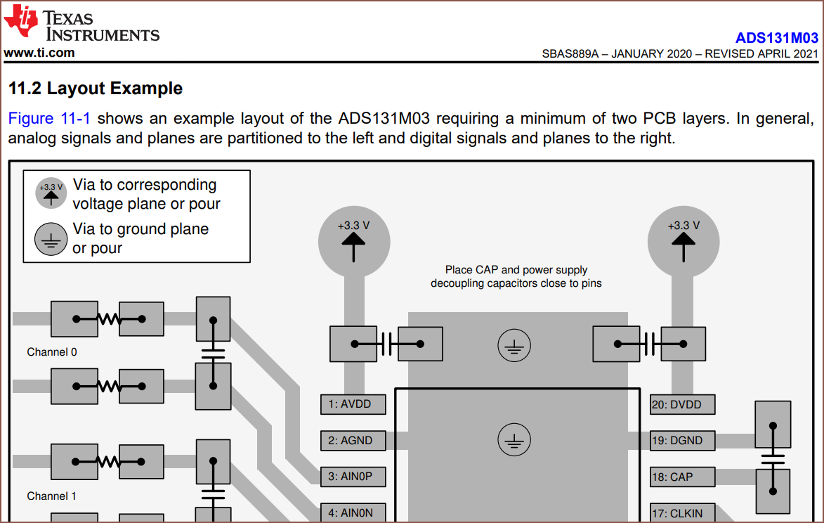
I've added more capacitors to this schematic, as recommended by the datasheet. The capacitor between the + and - signal was also present in the cheap scale I tore down, so it's probably needed. I'm going with a seemingly low capacitance value as I'm assuming that a higher one will take longer to react to changes.
 kelvinA
Discussions
Become a Hackaday.io Member
Create an account to leave a comment. Already have an account? Log In.