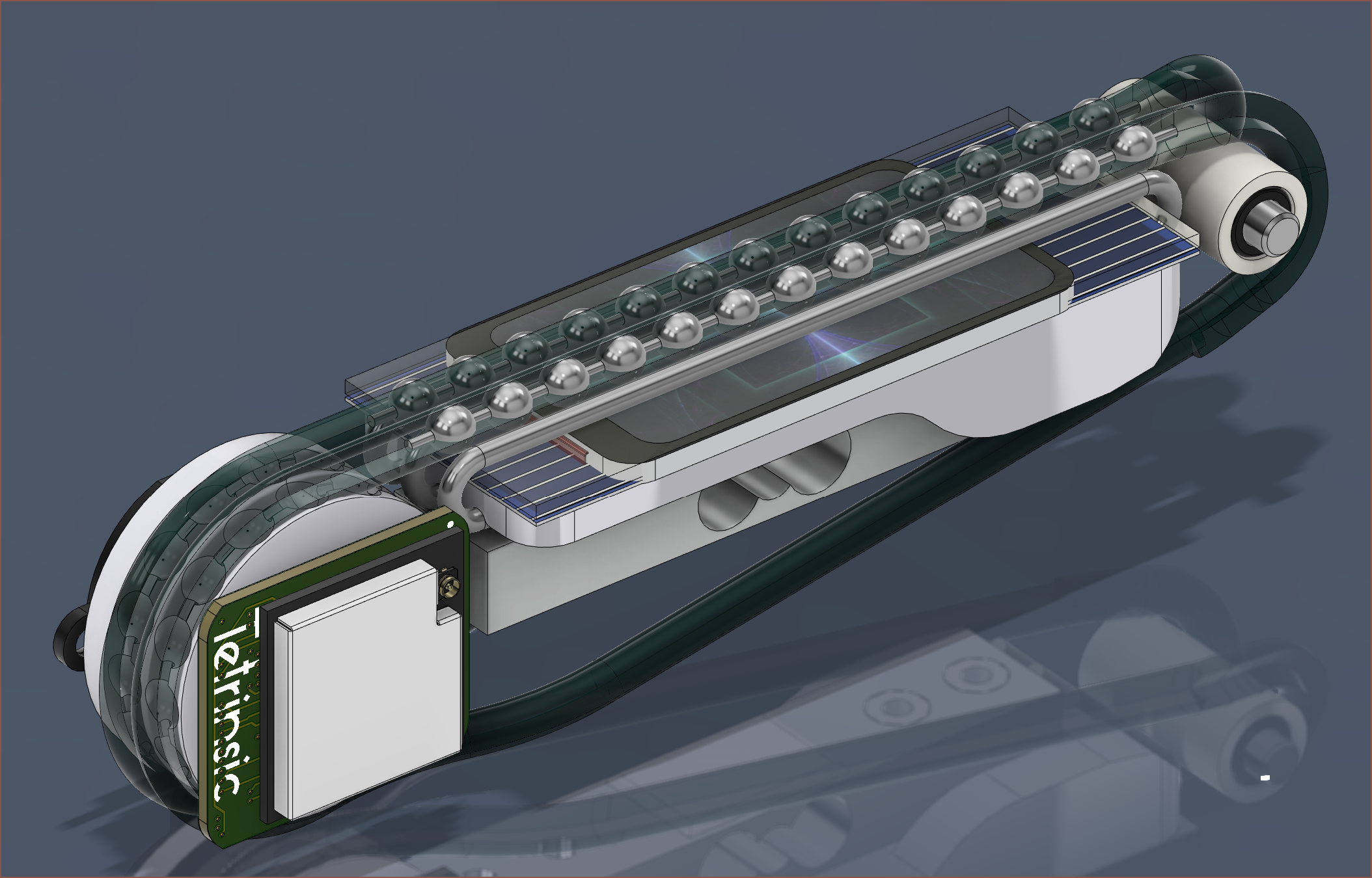
 I've done a "quick" (a.k.a. 60 minute) model of 3 more components.
 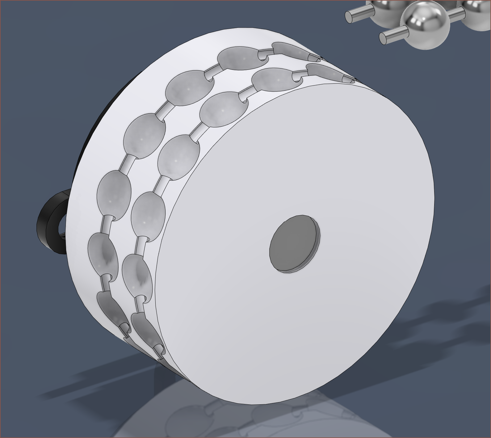 The sprocket now has 3d modelled "teeth" that I took inspiration from searching "ball chain" on thingiverse.
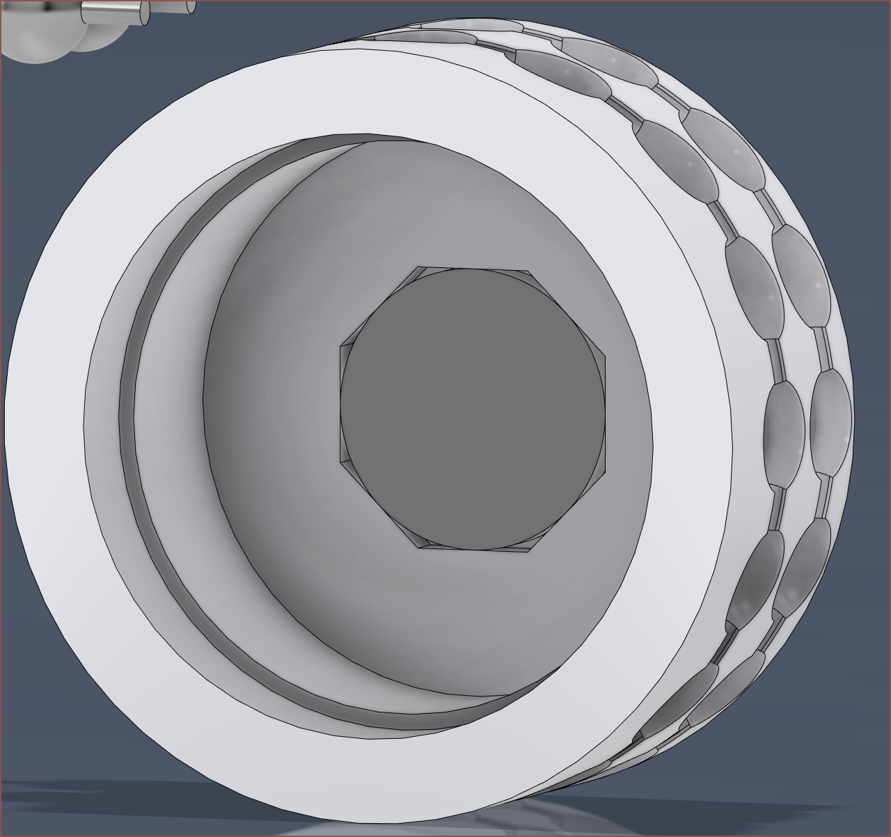 I've modelled it such that the diametric magnet is held inside. This hopefully makes it much easier to center on the motor.
I had to move the motor down a bit so that the minimum wall thickness of the pulley I like how the PCB coincidentally matches the edge of the chain path. I also like how simple this all looks, even though it's taken months on and off to get here.
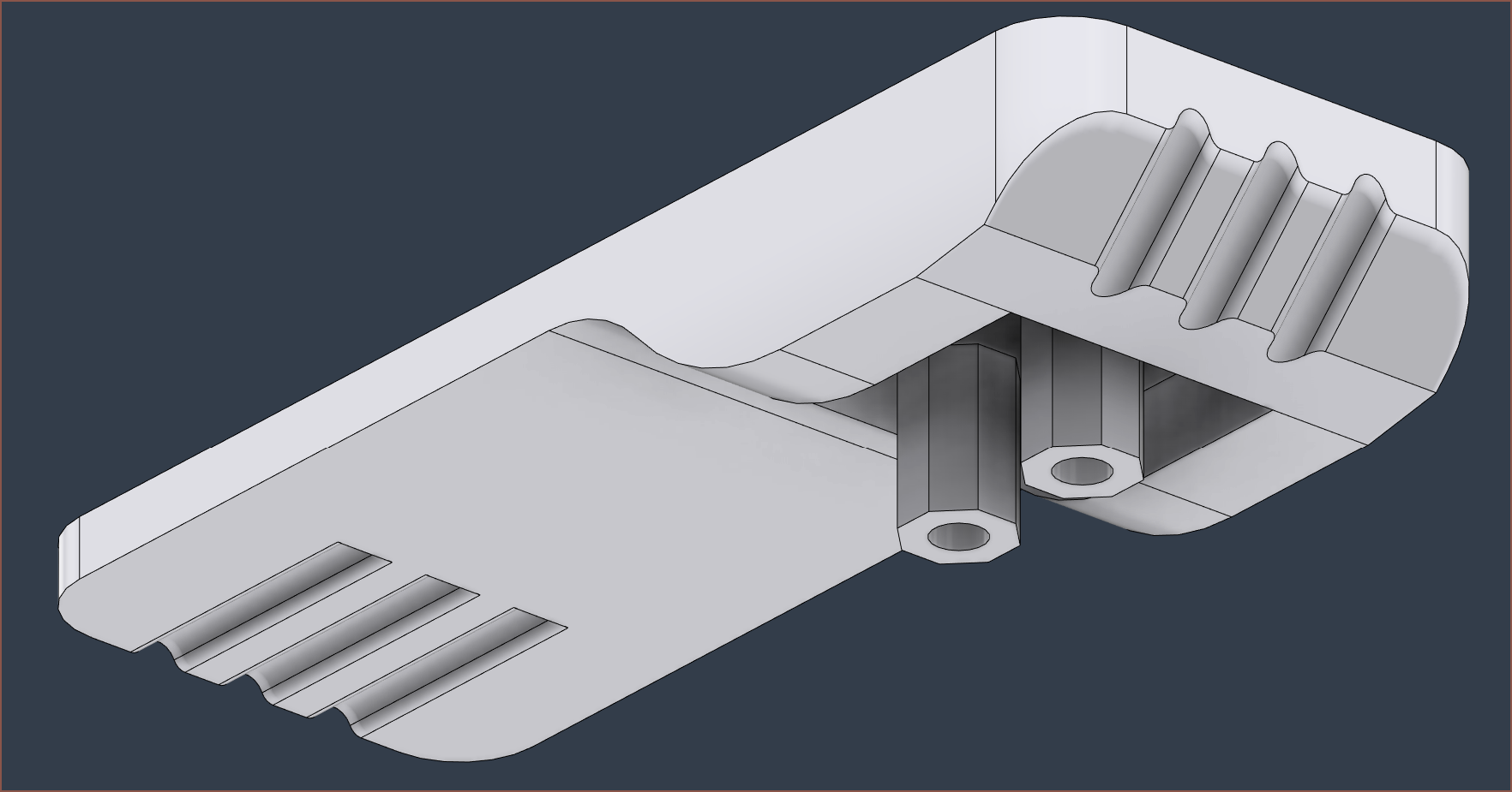
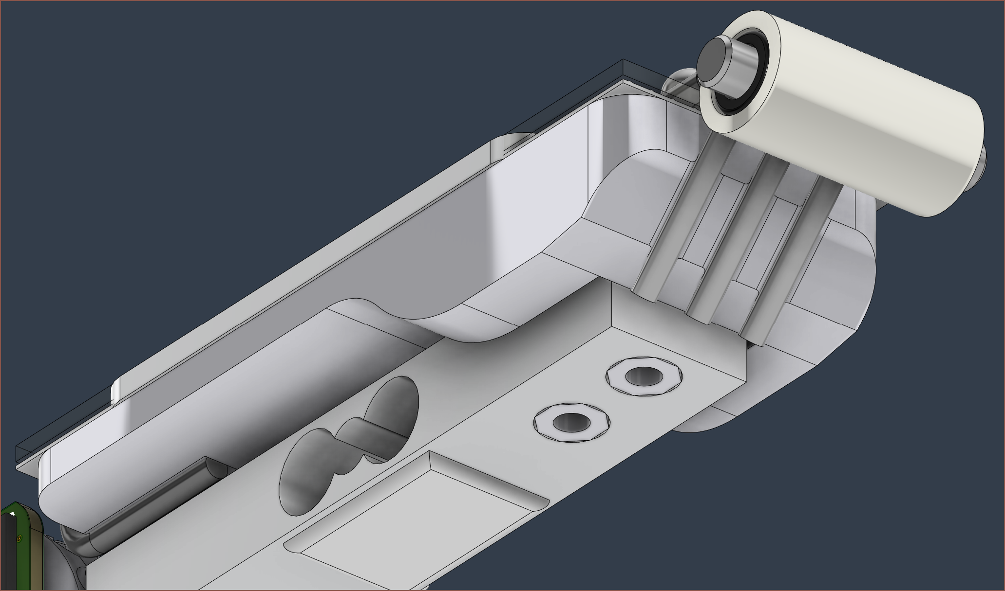 Then there's the start of the slider mount, as well as the pulley. There probably should be some kind of LCD wire cutout somewhere on it. This also might be the thing that holds the pulley, but since I haven't yet figured out a way of mounting the BLDC + PCB as a self-enclosed unit (hence, the mounting geometry would have to be created in Tetent/Leti instead of just worrying about mounting screws and clearance like the first Tetrinsic concept), I'm not in any urgency to compute a solution. Ideally, the tubes snap into place in the little trenches for them:
The pulley itself is a 3mm dowel + 2 needle roller bearings used in BMG extruders for FDM 3D printers + 5mm inner, 7mm outer tube. The tube material is either silicone or PTFE, though silicone is slightly cheaper.
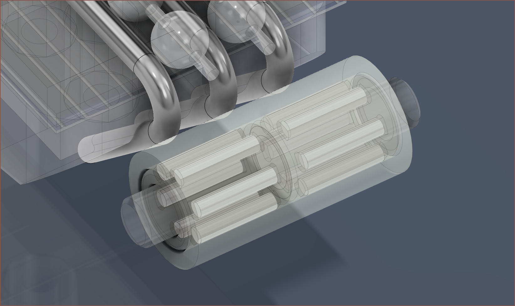
The reason I'm not using a metal bearing material because I want to dampen noise and any vibrations that may occur.
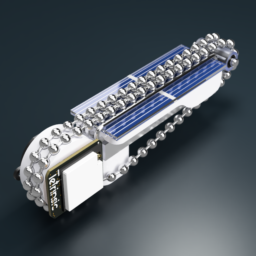
I think I might finally now have enough stuff conceptualised to actually create a proof-of-concept device, thought I'd have to make a USBC-to-24pin adapter / development board first. For Tetrinsic itself, the BOM so far looks like this:
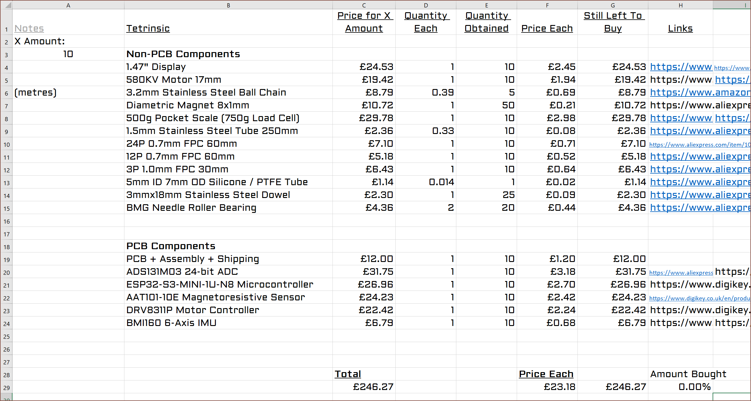
The price difference between the total and the per-each price is because some components, like the magnets, can only be bought in quantities exceeding what I need. As I expected, it was going to be around £250 for 10pcs. Not great, not terrible, but that's £200 per Tetent. Also note that this doesn't include costs for the solar cell version, though I'd imagine it'll be similar to the price of the 1.47" display.
The proof-of-concept would just have a 3D printed slider surface in the place of the LCD / solar cell.
 kelvinA
Discussions
Become a Hackaday.io Member
Create an account to leave a comment. Already have an account? Log In.