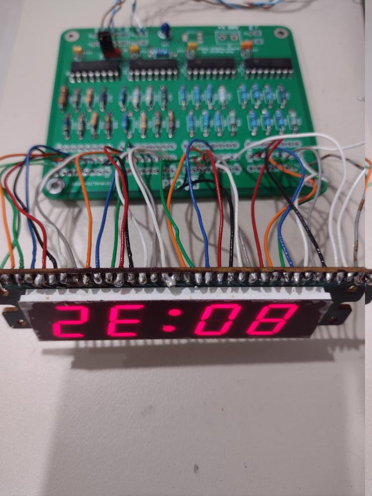
I've put another of this board to use to drive an alarm clock display. My bedside radio/alarm clock is failing so I'm replacing the dedicated clock chip from the 70s in it with a modern MCU based design. I have a second copy of the LED display used there with all segments brought out to the connector. The display is dim despite a current of about 5 mA per segment due to the era of the LEDs but that's ok for a bedside clock; you don't want to be kept awake by the light.
The display is being tested so it's upside down. But even if you flip the display mentally, you'll notice that the time is strange, it reads 80:32. The reason is the test program is sending out the serial data most significant digit first, so the correct time is actually 23:08. It's just a test program so I'm not bothered as long as it proves that the display is working.
I'll write up the alarm clock project when it's done.
Update, 2024-10-08: The write-up is at #Third life for a radio alarm clock
 Ken Yap
Discussions
Become a Hackaday.io Member
Create an account to leave a comment. Already have an account? Log In.