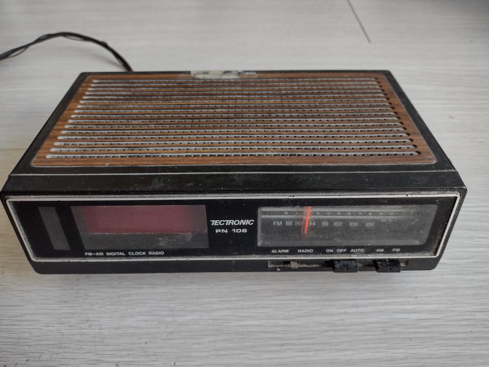
Once upon a time, in a country far far east away, a clock with a split-flap display was born. It had, besides the mechanical clock, an AM-FM radio which could be used as a wake alarm. It was already n-th hand when I adopted it from a garage sale sometime in the early 90s.
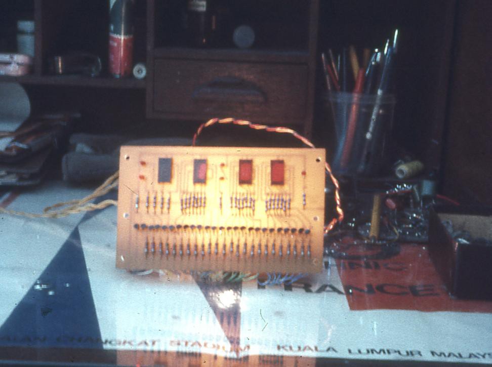
The mechanical display worked for a few years, then the motor failed. Not wanting to throw out this bedside appliance, I took the board from one of the first digital clocks I built back in the mid-70s, connected a 4-digit LED panel of similar vintage to it, and turned it into an electronic radio alarm clock. It wasn't the first display that had been used. Here's a picture from the mid-70s showing the first display, 4 small 7-segment LED packages. Terrible styling with such wide spacing but LED displays were novel and a bragging point to onlookers. Remember that this was before such displays were widespread in home electronics. The 5316 board is behind the display, connected by lots of wires. You can also see that I used heaps of transistors and resistors. I had plenty of both, thanks to grab bag purchases.
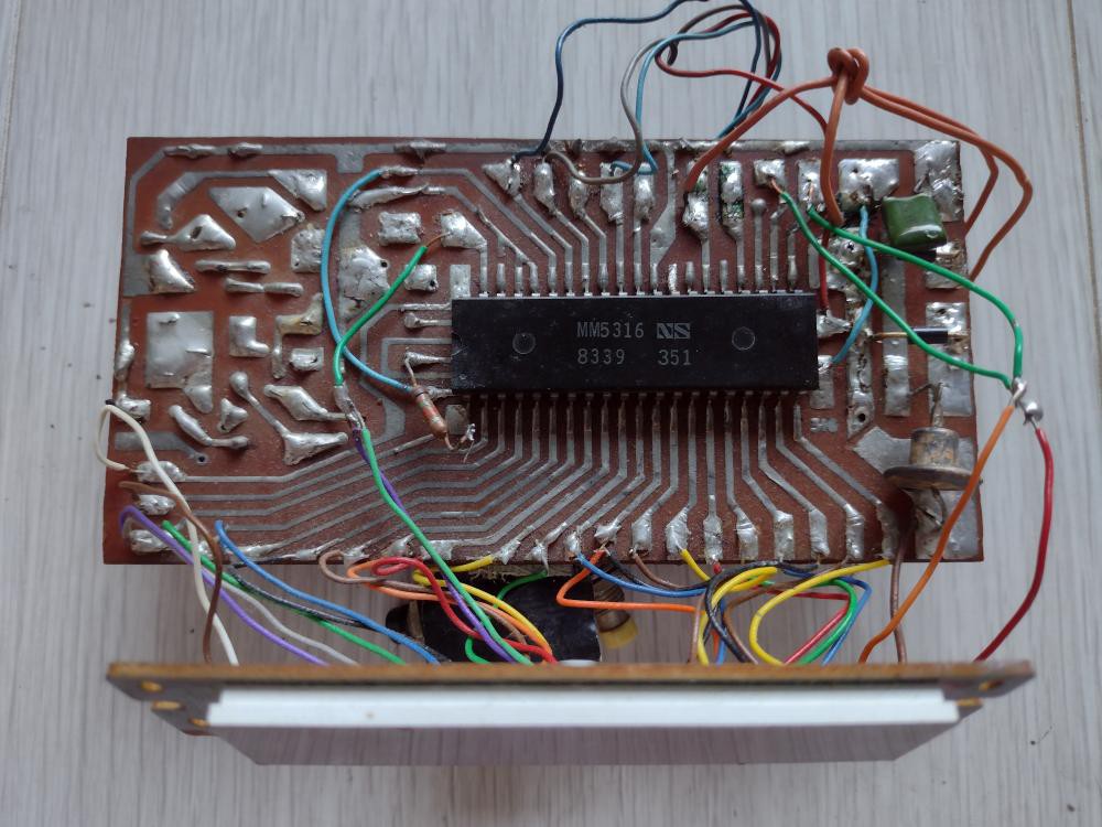
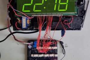
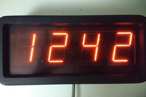
Here is the clock board now with the 4-digit LED panel, made by Toshiba, which had been picked up from some electronics lucky dip box. I fitted both into the space formerly occupied by the split-flap clock. Also notice that I was doing surface mount with THT chips all those years ago.
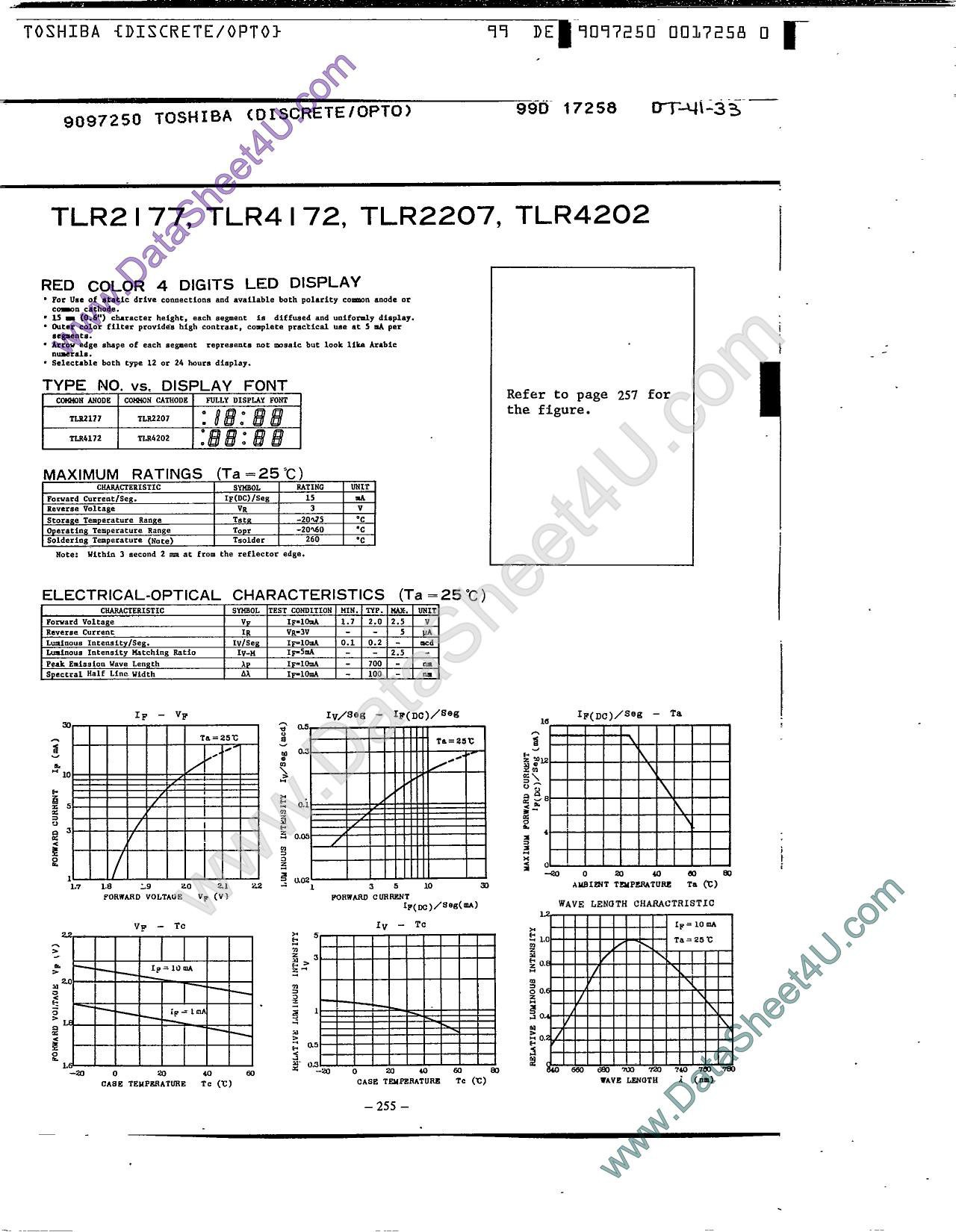
Out of curiosity, I did a web search for the ID on the back of the display module, TLR4202, and found a 5 year-old post on Stackexchange where someone was trying to replace it in their radio-clock. There was a link to a datasheet and I found this page. It didn't tell me anything I didn't already know but it was good to know that it was used on radio alarm clocks back in the day.
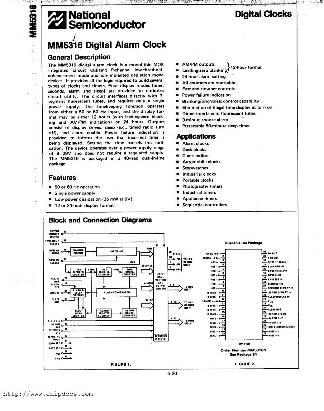
The 5316 chip was designed to drive VFDs non-multiplexed. Its nominal working voltage of 20-29V was a good match for such displays. Here's the first page of the datasheet. It uses mains frequency as the timebase. I was in fact powering the 5316 at a lower voltage of around 12V such that the AM and PM LEDs became power-fail indicators, so I called that a feature, an alive indicator. 😉
After many years of service, a couple of years ago the 5316 started playing up and the set buttons became erratic. I only set the time twice a year, at DST changes, as power outages are very rare here so I put up with the annoyance. But after I designed and built #3 line to 32 line output expander and found the second of two Toshiba 4-digit LED panels in my spares box, I formed the idea to replace the 5316 with a MCU.
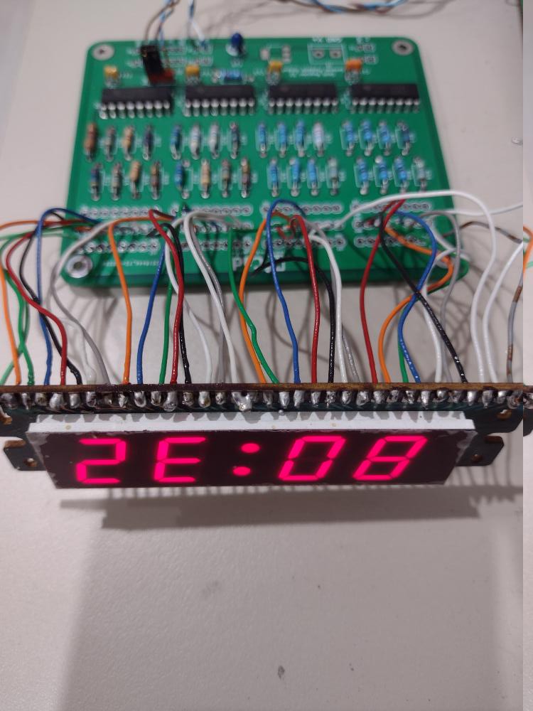
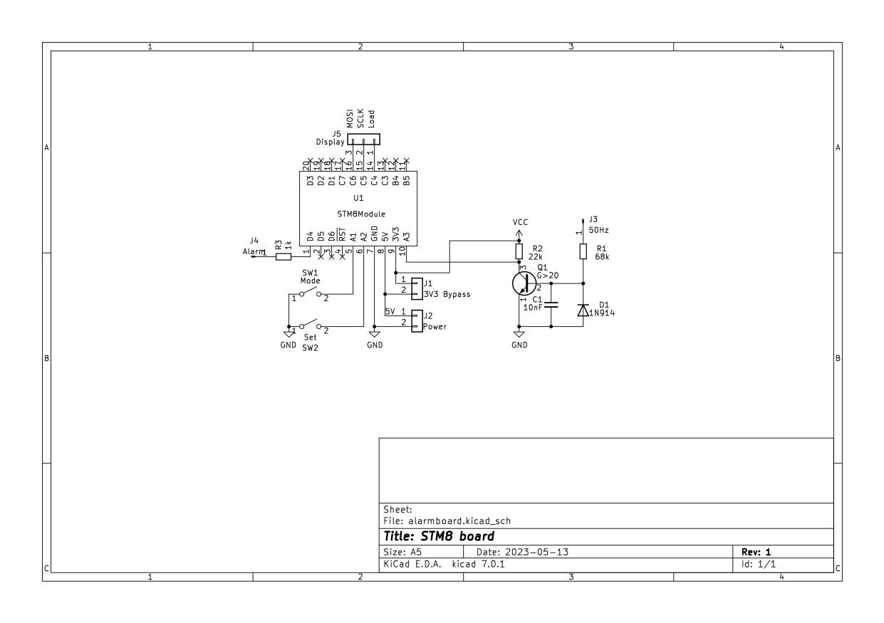
Wiring up the panel to the GPIO expansion board was straightforward if repetitive work. It took a while longer for me to wire up a STM8 Blue Pill board and a few surrounding components and write the firmware for it. As usual I procrastinated but with a DST change impending, I got going.
Problems found and solved
I couldn't get blinky to work on the Blue Pill. This turned out to be an upgrade to the SDCC version which caused timer interrupts to not work. The solution was to rebuild the library (SPL).
The colon didn't flash at 1 Hz and this turned out to be a dry joint in the 50 Hz timebase signal line.
The display showed the wrong time. By trial and error I discovered a possible compiler bug when passing an uint8_t argument which is then subject to division and modulo 10 operations. C requires widening char arguments to int anyway, so I changed the function signature.
The hours and minutes were displayed in reverse. Changing the direction of conversion to a serial stream for the 74HC595 shift registers fixed that.
I tried using the SPI pins to drive the 74HC595 shift registers but this resulted in spurious pulses at initialisation so I gave that up. I may return to the ifdefed code some future day but it's not important as SPI only saves bit-banging, but this MCU is very lightly loaded.
One of the two set buttons didn't work. A voltmeter measurement...
Read more » Ken Yap

 Zachary Murtishi
 Pierre-Loup M.
 zst123
"Tectronic": if you had two, you could make an oscilloscope.
(sorry - bad joke)