 Ken Yap
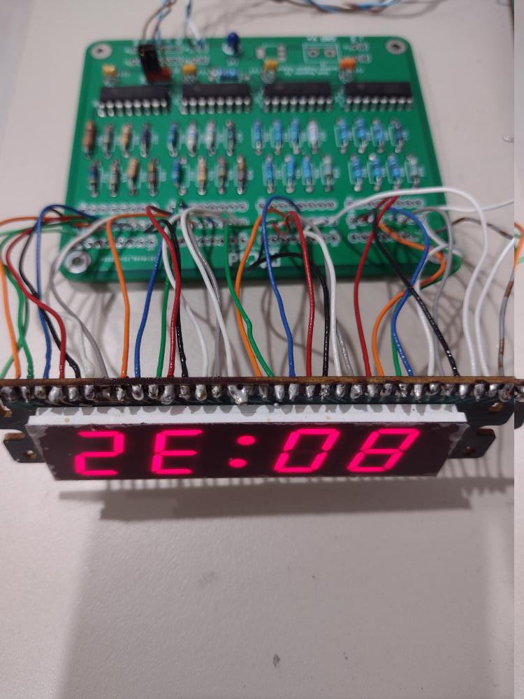
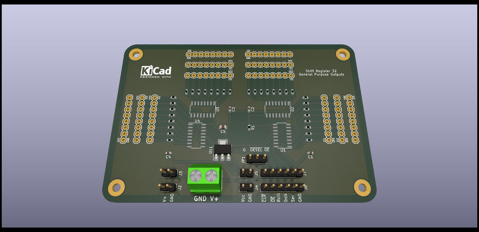
This is a driver board for the nixie cathode switching transistors in #Repurposing an old nixie thermometer. It converts 3 signal lines to up to 32 parallel outputs. I need 28 lines to drive the 4 nixies. Since a minimum of 5 boards had to be produced, I designed it to be versatile. The sharp eyed will notice that only 7 lines out of each octet are actually used for this application.
The minimum lines required to use this board are: GND, SER (data), SRCLK (shift), RCLK (strobe). Vcc depends on the power arrangement. You should jumper the ~OESEL (output enable select) to ground if you don't wish to disable the display by signal, or vary the output with PWM, from a controller. The ~SRCLR input is only needed for resetting the output by the controller.
This board is designed with optional aspects you can choose to include or not:
- As mentioned some lines don't need to be driven in smaller configurations.
- Between 1 and 4 74HC595s can be installed for 8-32 outputs, in steps of 8. Naturally only the resistors for the used outputs need to be installed.
- The 74HC595 can source or sink 6 mA current.
- The 74HC595 can operate between 2V and 6V. This can be chosen to suit the controller, e.g. 3.3V or 5V, and the power supply section if installed.
- The power supply section is optional. You can choose to power this from the controller. Or you could power the controller with this.
- Copper pads for data and output are duplicated so you can attach more connectors or even solder wires. The input power is also brought out to duplicate pads for piggybacking to other circuits, e.g. an auxiliary board.
- Although the connectors are rendered as vertical pin headers, you can use other kinds of connectors like pin sockets, or even solder wires to the pads.
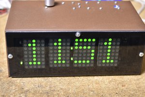
A simple Arduino test program is attached which alternates between the patterns 0x55555555 and 0xAAAAAAAA. LEDs connected to the outputs will alternate.
A future version will use SMT to shrink the size of the board and avoid soldering resistors, letting the PCB assembly service do that, soldering the rest by hand. In such a situation, the resistor values have to be all the same to minimise the cost. That will give me practice in ordering PCB assembly with the many offers around.
Update, 2025-03-04: A new version has been uploaded to Github which has been submitted to PCBWay for fabrication, and now validated. See the log https://hackaday.io/project/184239-3-line-to-32-line-output-expander/log/238911-smt-version-of-board-sponsored-by-pcbway
 rob
rob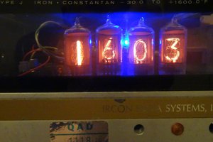
 Bharbour