 Florian Wilhelm Dirnberger
0. Outline
The basic technical concept for this Geiger counter is copied from biemster's ESP8266 project:
https://hackaday.io/project/12933-esp8266-geiger-counter
This sketchy design has several drawbacks since there is no control loop for the tube HV, an issue that will be addressed here.
I use the Raspberry Pi Pico 1 for prototypes, so connecting the device to the Internet will briefly be discussed yet is beyond the project scope (for the Pico 1 has no IoT capabilities per se).
Connection to a GPS HW in order to display/store CPM values together with a geographical location will be within the project scope.
1. Prototypes
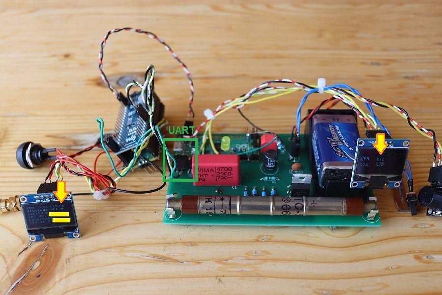
Status as of June, 2024
With an SSD1306 0.96'' OLED and a buzzer. Also connected is a Pico-GPS-L76B (GNSS Modul) to determine the geographical location, including an extra Pico because using an extra Pico makes it easier carrying out experiments (so it is not a final concept, obviously).
The Picos communicate thru the UART interface.
Demo video
In a nutshell
On the left OLED you see a CPM values history (13, 14, 15, 10) together with a geographical location (obscured for privacy reasons).
In order to save power, the OLED on the right shows only a bare minimum of data (every pixel consumes energy), and the brightness is diminished. More information farther below.
2. Schematic
The device comprises in essence the MCU board, the boost converter, a power supply network, the HV control loop and of course the Geiger tube itself.
Diode D1 prevents immediate discharge of capacitor C1 and tube voltage is building up quickly. The coil voltage peaks into the double, then triple digits every time the transistor cuts off (see simulation results below).
Upper limit of the PWM frequency is a few kHz: around 2 kHz the HV is starting to drop considerably (edit: with UF4007 not longer the case, see "Note 2").
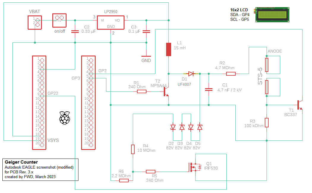
Note 1: values for R1, R5, C2, C3 can be varied (it is mostly irrelevant for the power consumption whether R1 is 240 Ohm or, say, 1 kOhm for I am using a control loop anyway)
Note 2: UF4007 is superior to the originally used 1N4007 (UF4007 better suited for higher frequencies)
Note 3: I've changed the inefficient (but cheap) L7805CV linear voltage regulator to LP2950; C2 isn't really necessary here but doesn't hurt either
Note 4: as a general rule, the anode resistor should be soldered physically close to the tube
3. G-M tube SBM-20 (or STS-5, Cyrillic CTC-5)
With this Soviet Union tube you can detect Beta and Gamma radiation (as with any Geiger tube, you cannot distinguish them), but not Alpha. For the tubes you are seeing on the pictures I paid around 30€ (in 2022, probably more expensive now), including shipment.
Technical data: SBM-20_GER1.pdf (mikrocontroller.net)
For registering pulses by the counting system proper working conditions have to be established. That means in practical terms generating a tube voltage within the Plateau area.
Beyond the characteristic "Knee" all pulses are (or ought to be) counted. Below the starting voltage, no pulses are counted at all.

4. Emitters, natural radiation and testing
For testing the general viability I use small pieces of Uranium glass (this matter doesn't radiate intensely for obvious reasons).
The natural radiation is detected about 20 CPM (in 49°46xxx' N, 11°12xxx' E) with the current prototypes. There's of course the inherent randomness in the measured data.
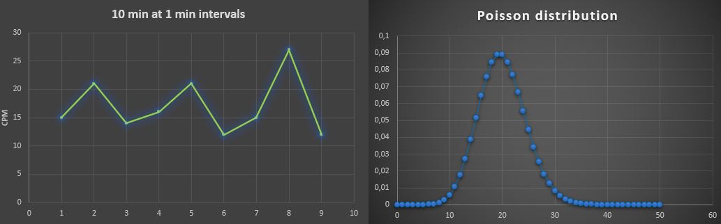
Note: for a reasonably accurate realization of the underlying probability distribution there are a lot of samples needed, the given graphs are just for illustration (for seldom events such as radioactive decay, Poisson distribution can be a helpful mathematical model).
5. Program development and display of data
5.1 Conceiving an algorithm from scratch
I use C language for program development. In order to work with it, I had to install the tool chain (the C development...
Read more »


When you read about project from Příbram and see note about Příbram :D. Anyway, thanks for it, i have long term plan to build one but i'm missing enough free time.