Close
0%
0%

Geiger counter

Radiation measurement device w/ Raspberry Pi Pico and STS-5 tube

Similar projects worth following
The technical concept ("boost converter") for this microprocessor controlled radiation measurement device (Geiger counter) is copied from biemster's ESP8266 project.

https://hackaday.io/project/12933-esp8266-geiger-counter

There are drawbacks about that very basic design since there is no control loop for the tube HV, an issue that will be addressed here.

I use the Raspberry Pi Pico for prototypes, so connecting the device to the Internet will briefly be discussed yet is beyond the project scope (for the "classic" Pico has no IoT capabilities per se).

Connection to a GPS HW in order to display/store CPM values together with a geographical location will be within the project scope.

1. Prototypes

Status as of June, 2024

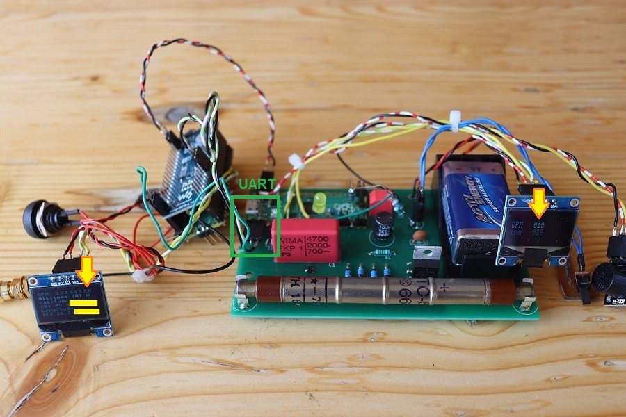
With an SSD1306 0.96'' OLED and a buzzer. Also connected is a Pico-GPS-L76B (GNSS Modul) to determine the geographical location, including an extra Pico because using an extra Pico is easier for conducting experiments.

The Picos communicate thru the UART interface. 

Demo video

In a nutshell

On the left OLED you see a CPM values history (13, 14, 15, 10) together with a geographical location (obscured for privacy reasons).

In order to save power, the OLED on the right shows only a bare minimum of data (every pixel consumes energy), and the brightness is diminished. More information farther below.
2. Schematic

The device comprises in essence the MCU board, the boost converter, a power supply network, the HV control loop and of course the Geiger tube itself.

Diode D1 prevents immediate discharge of capacitor C1 and tube voltage is building up quickly. The coil voltage peaks into the double, then triple digits every time the transistor cuts off (see simulation results below).

Upper limit of the PWM frequency is a few kHz: around 2 kHz the HV is starting to drop considerably (edit: with UF4007 not longer the case, see "Note 2").
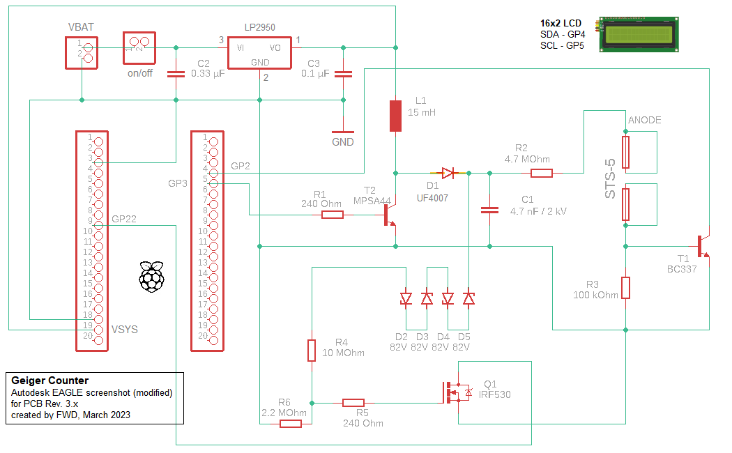
Note 1: values for R1, R5, C2, C3 can be varied (it is mostly irrelevant for the power consumption whether R1 is 240 Ohm or, say, 1 kOhm for I use a control loop anyway)

Note 2: UF4007 is superior to the originally used 1N4007 (UF4007 better suited for higher frequencies)

Note 3: I've changed the inefficient (but cheap) L7805CV linear voltage regulator to LP2950; C2 isn't really necessary here but doesn't hurt either

Note 4: as a general rule, the anode resistor should be soldered physically close to the tube

3. G-M tube SBM-20 (or STS-5, Cyrillic CTC-5)

With this Soviet Union tube you can detect Beta and Gamma radiation (as with any Geiger tube, you cannot distinguish them), but not Alpha. For the tubes you are seeing on the pictures I paid around 30€ (in 2022, probably more expensive now), including shipment.

Technical data: SBM-20_GER1.pdf (mikrocontroller.net)

For registering pulses by the counting system proper working conditions have to be established. That means in practical terms generating a tube voltage within the Plateau area.

Beyond the characteristic "Knee" all pulses are (or ought to be) counted. Below the starting voltage, no pulses are counted at all.
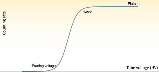
Characteristic curve

4. Emitters, natural radiation and testing

For testing the general viability I use small pieces of Uranium glass (this matter doesn't radiate intensely for obvious reasons).

The natural radiation is detected about 20 CPM (in 49°46xxx' N, 11°12xxx' E) with the current prototypes. There's of course the inherent randomness in the measured data.

Note: for a reasonably accurate realization of the underlying probability distribution there are a lot of samples needed, the given graphs are just for illustration (for seldom events such as radioactive decay, Poisson distribution can be a helpful mathematical model).

5. Program development and display of data

5.1 Conceiving an algorithm from scratch

I use C language for program development. In order to work with it, I had to install the tool chain (the C development system) on my Raspberry Pi.

Necessary for the HV-generation is a PWM with a frequency of e.g. 10 kHz and a duty cycle of e.g. 60% (output here on GP3, see paragraph 5) - those are empirical parameters.

As we have an MCU connected there are several ways how to handle measurement data. 

Triggering IRQs and counting them (here on GP2) is one pragmatic method, for a pulse (gas discharge, i.e. counting event) has a duration of about 0.3 ms. Problems may arise with high counting rates for the interrupt handler might be unable to deal with them properly (up to about 500 CPM, a counting rate I'm able to generate with the emitters, everything seems alright).

5.2 Displays...

Read more »

LP2950ACZ50.pdf

Linear 5V voltage regulator

Adobe Portable Document Format - 562.56 kB - 03/14/2023 at 15:27

Preview

HALTER_9V_DB.pdf

Drawing 9V battery holder

Adobe Portable Document Format - 77.25 kB - 11/24/2022 at 13:21

Preview

Buzzer module (active).pdf

Data sheet Buzzer.

Adobe Portable Document Format - 526.54 kB - 06/25/2022 at 18:52

Preview

MPSA44-D.PDF

Data sheet HV transistor

Adobe Portable Document Format - 121.79 kB - 04/14/2022 at 13:48

Preview

BC337-D.PDF

Data sheet transistor

Adobe Portable Document Format - 183.00 kB - 03/04/2022 at 06:30

Preview

  • 1 × Raspberry Pi Pico Microcontroller board
  • 1 × MPSA44 Discrete Semiconductors / Transistors, MOSFETs, FETs, IGBTs
  • 1 × BC337 BJT; SMD alternative: BC817
  • 2 × Resistor 240 Ohm Or similar, value not so critical
  • 1 × Resistor 100 kOhm

View all 20 components

  • HV measurement

    Florian Wilhelm Dirnberger11/12/2022 at 13:34 2 comments

    HW Rev. 2.x

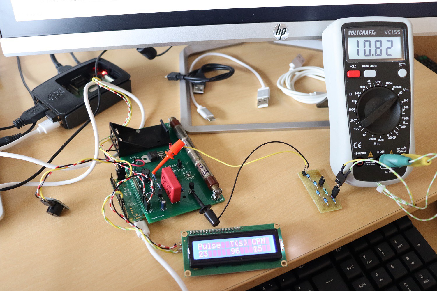
    Simple HV measure arrangement: consisting of four 82V Zener diodes, one 10 MOhm and one 2.2 MOhm resistor (series connection). These are parallel to the tube Anode and GND.

    The Voltmeter is parallel to the 2.2 MOhm resistor.

    On the picture you see a voltage of some 11V, what means the HV amounts in this case to:

    HVtube = 11 + (11/2.2)*10 + 4*82 = 390V 

    (the voltage is higher actually because the Voltmeter has an internal resistance in the 10 MOhm range so the measured value is slightly off)

    Varying the PWM parameters in the SW would lead to higher and lower voltages, respectively.

    This assembly could be the basis for a control loop design (edit: realized).

View project log

Enjoy this project?

Share

Discussions

tormozedison wrote 05/24/2022 at 19:22 point

The counter on some of your photos is not SBM-20, but STS-5, an older version with similar specifications.

  Are you sure? yes | no

Florian Wilhelm Dirnberger wrote 05/25/2022 at 04:06 point

Ah, you are apparently right. Then the seller from ebay kinda cheated me :-D. I will add a note on this project page.

  Are you sure? yes | no

tormozedison wrote 05/25/2022 at 06:26 point

I won't call it cheating, STS-5 is more vintage and therefore rare.

  Are you sure? yes | no

Nazwa wrote 04/17/2022 at 17:22 point

this will be working with radioactive @home?

  Are you sure? yes | no

biemster wrote 04/07/2022 at 12:43 point

Nice! I've been looking to revive the project you've based this on, so if you find improvements over that previous schematic please add that to the logs!

  Are you sure? yes | no

Florian Wilhelm Dirnberger wrote 04/07/2022 at 12:49 point

Hi :) hope your project gets en route a little boost in attention as well.

  Are you sure? yes | no

Florian Wilhelm Dirnberger wrote 04/04/2022 at 15:22 point

Thanks Alan for your comprehensive answer. You spotted a flaw in the design that wasn't really obvious to me. I'll try out different transistors in future prototypes.

  Are you sure? yes | no

agp.cooper wrote 03/31/2022 at 04:36 point

Does not work that way. Your particular transistor is breaking down at 400v.

Providing the power is low, it should not hurt the transistor.

Better if you used a voltage doubler or a transformer.

Alan

  Are you sure? yes | no

Florian Wilhelm Dirnberger wrote 04/02/2022 at 17:25 point

What exactly is the problem with the µC/transistor combination for I can effortlessly diminish or increase voltage by changing duty cycle and frequency via SW.

  Are you sure? yes | no

agp.cooper wrote 04/04/2022 at 12:32 point

Hi Florian,

I had a closer look at the CE breakdown voltage and I see it is rated at 1mA. This means the transistor parameter is for avalanche breakdown mode, so yes the zero current (peak) breakdown would be higher, as you have found.

So what is the problem? Basically you are operating the transistor in an area of its operating envelop that has not been defined.

Often a MOSFET is used in this application. One reason is that the breakdown voltage is better defined and the maximum "inductive power" the transistor can absorb is stated. For an IRF470 it is 500v and 30 mJ. So providing you dissipate the power there is problem operating in avalanche breakdown.

So at some point above the 300v the MPAS42 transistor will go into avalanche breakdown mode. Your circuit will need to limit the power to some unknown amount.

That is why I don't like this type of circuit.

If you use a diode double then avalanche  breakdown will not be a problem. 

Regards Alan

  Are you sure? yes | no

agp.cooper wrote 03/26/2022 at 10:34 point

I doubt you will get 400v to 500v from this circuit as required for a geiger tube to operate.

The breakdown voltage of the MPSA42 is only 300v. 

Circuit simulators do not always model transistor breakdown voltage. 

  Are you sure? yes | no

Florian Wilhelm Dirnberger wrote 03/26/2022 at 10:55 point

Yes you are correct. MPSA44 would be better but wasn't available for my first prototype. Next prototype will have different transistor.

Edit 03.04.: Carried out a further measurement. MPSA42 works even with >400V since that voltage is actually (i. e. steady-state) present on the cathode of the diode, not on the anode. I am gauging some 400V, what is the voltage's under limit in any case (oscilloscope with probe has 10 MOhm impedance). 

  Are you sure? yes | no

Similar Projects

Does this project spark your interest?

Become a member to follow this project and never miss any updates