Sebastian
Why develop another power analyzer?
First of all, commercial power analyzers (PA) are expensive and mostly designed for use on-site, for example for testing motors etc.
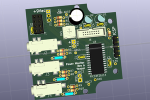
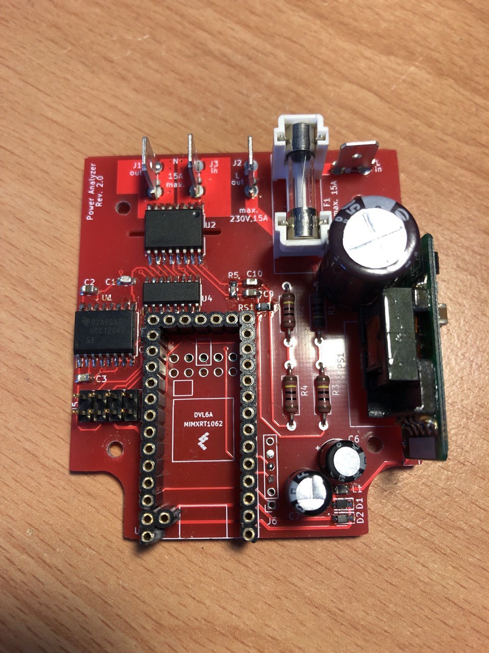
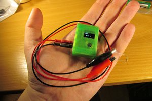
The goal of this project and the bachelors thesis was, to develop a low-cost power analyzer with the most important features when integrated into devices or used as a small adaptor - which was achieved.
How to use
The PA is designed to plug into a common socket here in Germany.
After plugging it in, the socket on the other side can be used for appliances with a power draw according to the fuse built in, but 15A at max.
The display then starts to show the measured values
- RMS Voltage and Current
- Power consumed
- Current time (if synced with a PC)
- Harmonic distortion factors (THD) of current and voltage
- Power factor of the device
- Phase angle
Software
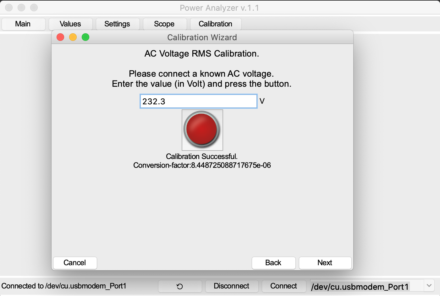
Additionally, a software GUI is provided to configure the chip.

The chip's EEPROM can be configures via the settings page of the GUI. First, the settings have to be initialized, to not accidentally overwrite a setting.

The measured values can be read with the live page view.

The scope page shows the current voltage and current. On the bottom is a live view of the voltage and current harmonics, respectively.
Further development
Following things are planned for the future:
- Do some software refactoring
- Eliminate bugs
- Additional configuration of measured data
- Adding a calibration "wizard"


 jaromir.sukuba
 Daniel
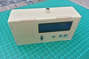
 martin2250