Sebastian
-
High-Voltage immunity testing
09/30/2021 at 15:43 • 0 commentsLong time no see...
One sunburn during vacation later, I finally got to test the immunity of the module.
Before the results, I will briefly go over the "but why". The answer is pretty simple: Because in the power grid, natural occurring phenomenons such as lightning strikes can do a lot of destruction. Of course, there are many other safety features in residential and industrial environments, like surge protection systems that "deflect" most of the damage. The most danger comes from inside the system, like moles in spy movies. If the system is not well protected, this can even lead to the destruction of it.
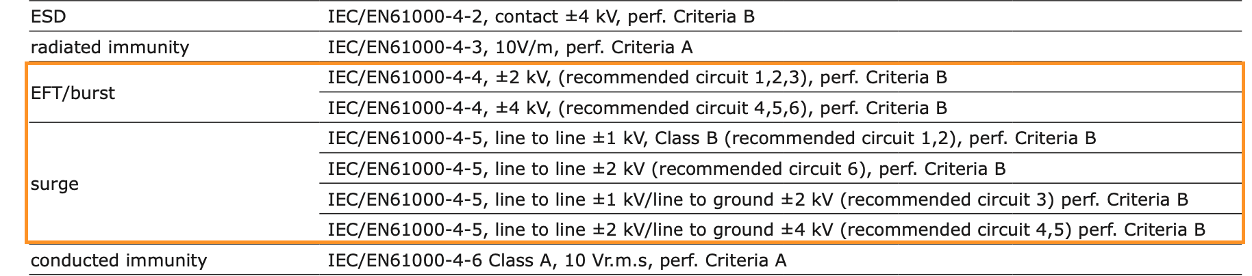
(Serious) manufacturers of power supplies and isolation equipment will indicate the immunity for their component. A good example is the AC-DC converter used in this project, the PBO-1-S5.
![]()
Next to (radiated) emissions and electrostatic discharge, there are two types of surges that can occur in a system.
1. Electrical Fast Transients (EFT)/Burst surges are rapid needle impulses that simulate the switching of a circuit breaker or a large load in general.
2. Surges, that are a "combination wave (1.2/50;8/20)" of a voltage that with 1.2µs risetime and a 50µs fall and a current with a rise(fall)-time of 8(20)µs. This simulates lightning strikes as well as switching of large load.
For the test, my university provided the testequipment necessary for this job. Namely the Schaffner NSG 600 with the modules 623 (combination wave) and 625 (EFT/Burst).
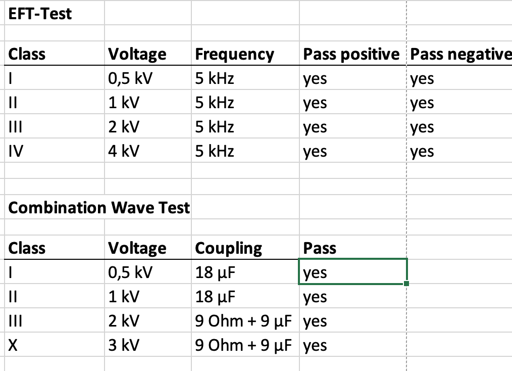
The adaptor can be safely plugged in and via a remote, I was able to start the test.The results are pictured below:
![]()
The generator was only capable of a 3kV surge, so this had to be the special class.
I noticed one strange thing with a 4kV EFT/Burst, where the display would draw white lines and ultimately gave out. Just to be sure, I ran the test twice to make sure it wasn't just a fluke (As with every other test), and what do you know? The second test ran without any problems. A third test, too.
In the end, I declared it immune to all tests conducted. SUCCESS!
-
Display Cover in FreeCAD
08/28/2021 at 12:27 • 0 commentsI wanted to work with FreeCAD a long time. Yesterday I finally had the time and made the display cover for the adaptor-housing. It already has some additions, that I plan to make (touch controls for the menu) and therefore needs a bigger cut-out in the housing.
I will use the 3d-printer at the university to print a prototype and to see if everything works out as planned, because my experience with 3d-printing is very limited to say the least. The FreeCAD project files are added to the project page.
![]()
-
Calibration demonstration
08/15/2021 at 12:19 • 0 commentsHere is the video to the calibration process. Have fun!
If you have any problems or feedback to the video, let me know.
-
Finished Calibration Wizard
08/14/2021 at 07:23 • 0 commentsSo yesterday I was able to finish the calibration wizard. Both offset correction and fine-trim work pretty well, as well as RMS voltage and current.
I am currently working on a short demonstration video, showing the process. I hope I get it done until tomorrow.
The current version is in the Github repository.
What comes next?
1.
As mentioned in a previous log, I plan to test the design for immunity against voltage / current transients. I am eager to see the results.2.
A build-documentation will come. I ordered a few PCBs, which should arrive in the next days. Unfortunately, I haven't got another housing, so the current one has to suffice. I will keep you updated! -
AC Calibration: Conversion factors
08/12/2021 at 14:43 • 0 commentsIn my previous project log, I wanted to send the calibration factor and the expected value directly to the teensy. I found it was easier to just calculate the conversion factor directly and send that value over. This saves some calculations and makes the overall program a little bit simpler.
And it works very well.
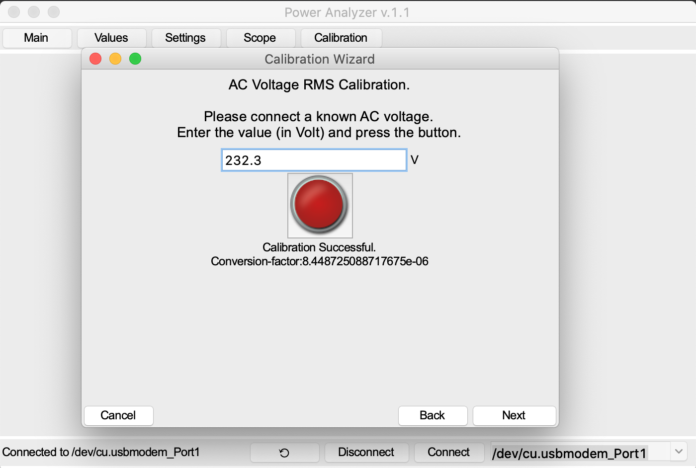
After plugging it in, you can measure the voltage with a multimeter (or just assume 230 V (more inaccurate)). The measured value van be entered into a value field.
The function the reads 10 values from the teensy and calculates the mean. The conversion factor is then calculated by
conv_factor = expected / rms_code .
Because the conversion factors are usually in the range of 10^-6 to 10^-5. Because of the necessary accuracy, the bitwidth for the fixed-point values was increased to 24 bit, with 23 fractional bits. With a press on the red button, this value is then sent to the teensy, which stores it in its EEPROM.
At startup of the GUI, when connecting to the teensy, these values are synchronized.
The IRMS calibration works analogous.
Here is a screenshot of the VRMS calibration:
-
Additional calibration values
08/12/2021 at 10:41 • 0 commentsDuring the implementation, I found a missing key-feature. As proposed in the last weeks project log, I initially thought that only the calibration factors for the VRMS and IRMS calibration matter. In order to calculate the correct scaling value for the value measured by the IC, it is necessary for the user to enter the expected RMS value of either current or voltage.
To store these values, the Teensy-EEPROM will be used as well. The expected values are floating-point, so they have to be converted beforehand to an integer, that can be represented as a binary number (floating point too, but the conversion is more complicated). So I chose a fixed point format, which is used by the ACS as well. The conversion is very easy :
with the floating point number f , and the number of fractional bits bw .
This can be stored very easily in the EERPROM and provides a good accuracy of 3.9mA for an 8-bit fractional part.
-
Calibration Wizard GUI
08/06/2021 at 16:24 • 0 commentsToday was GUI-programming time. Functionality is not yet implemented, but the formulas are written down and waiting to be implemented and tested.
The wizard is accessible via a button next to the scope window. The serial bus instance is passed as an init-parameter, for sending and receiving data to and from the teensy. GUI programming (with tkinter) is a bit tedious, so I am happy to be done with the main workload in this matter. Next week it is finally ready to test!
On another matter: Immunity test
I've got the possibility to test this device with a surge generator (Schaffner NSG 623) for its transient immunity. In theory, it is able to withstand voltage spikes up to 3 kV. But first I will finish the calibration wizard and of course I have to study the handbook.
-
Saving calibration settings
08/05/2021 at 13:03 • 0 commentsAfter running the calibration wizard, the calibration data must be saved.
For the calibration of the ACS71020, 6 values are required:
- crs_sns for setting the coarse gain
- sns_fine for the fine trim
- qvo_fine to set the offset
- pacc_trim for active power
- VRMS calibration factor
- IRMS calibration factor
The first 4 values are stores in the chips own memory. The IRMS and VRMS calibration factors are set in the code directly. To enable changing these values without reprogramming the teensy, another way of storing these values has to be chosen.
Last week, I was searching the ACS-chip for empty memory locations. A much easier solution is to use the internal EEPROM of the Teensy 4.0, which can store up to 1080 bytes of data. EEPROMs are known to be limited in write-cycles (100 000 cycles in this case), but usually a calibration won't be done that often anyways. Both calibration factors are only 32 bytes each, so there is enough space left.
EEPROM-access
The internal EEPROM can be accessed with the EEPROM-library easily. Each write stores 1 byte at a given address, so 4 writes have to be done in total. Reading values is analogous. An mcu_read() and a mcu_write() function serve as a wrapper to take care of this task.
Of course, a command from the serial input should be able to set those values as well.
Function changes
The calcVRMS and calcIRMS function both use the calibration factors. The constants are now variables. Everything else remains the same under the assumption, that AC calibration will be done with 230Vrms.
-
Calibration wizard - first thoughts
07/31/2021 at 13:41 • 0 commentsThe calibration wizard will be implemented similar to the waveform view, in a separate window.
It will guide through the calibration process, by calculating recommended settings, which can be accepted or ignored. The following calibrations have to be done:- Voltage
- RMS with a calibration factor
- Current
- RMS with a calibration factor
- Raw Values in terms of
- Coarse Gain
- Offset
- Fine trim
I will try to present the first results until the end of the next week.
- Voltage
Power Analyzer based on a COTS Power Monitoring IC
The idea of this project is the development of a power analyzer based on the ACS71020 power monitoring IC.