 marcoA152
-
1The wiring
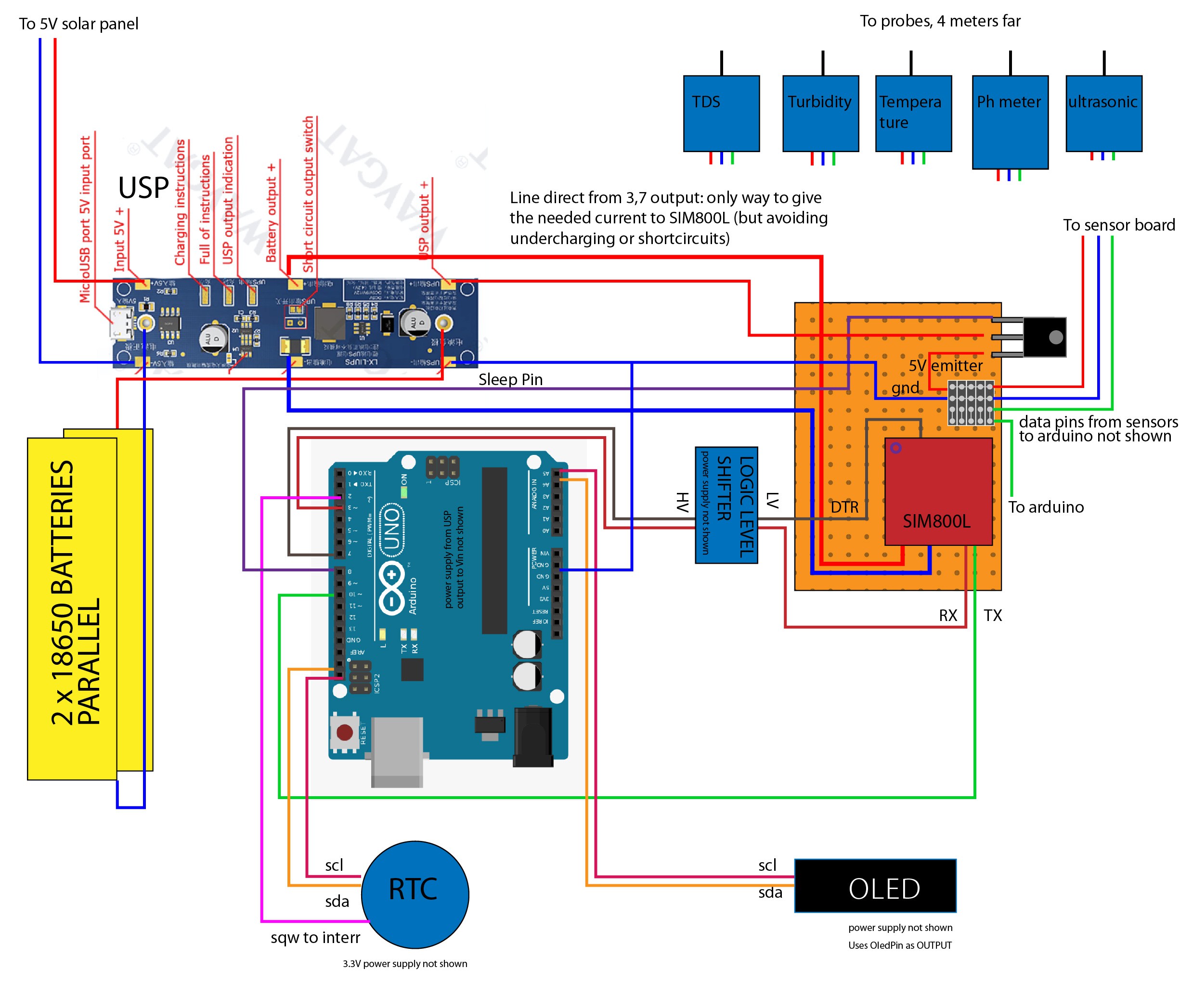
Here a partial schematics of the sensor box:
- all the power supplies wires (5V and GND) are not shown
- the gray square on the right is a group of header pins: the "DF robots gravity series" sensors have a standard connector with 3 wires (5V, GND and data), I've passed the data line to Arduino thru a fourth pin (see image).
To optimize battery consumption all the sensors are turned on/off thru a transistor controlled by "Sleep Pin HIGH/LOW".
Instead of a voltage divider, I've used a logic level shifter to comunicate with the SIM800L (not 5V tolerant on RX pin and (maybe?) also on DTR. I've used it also in this case)
After a lot of efforts, the only way to give the needed current to SIM800L (and avoiding undercharging or short circuits) is to use the direct battery output from the USP.
I've used fat wires (for 220V!) for the connection, without them the current is too low and the SIM800L still blinking fast without registering on the net (rebooting after 7 blinks).RTC and OLED screen shares the same SDA&SCL but from two different places from the board.
As Interrupt I've used Arduino pin 2 and SQW pin of the RTC (many guides about this online)
![]()
-
2The code
I will try to comment the code used for the sensor-box, this is the latest version consider that there's 6 version.
The weirdest problem i've encountered is the heap fragmentation, as a self learning guy, I've wildly used Strings (especially in a past version where the time is taken from the GSM net), after this issues solved now the board run smoothly days and days.
You can find the full code here
In this first part there are the libraries and variables,
the "SSD1306AsciiAvrI2c.h" for the OLED screen is the best for lower memory consumption.
the variables are declared in this ugly way because... I've changed them a lot of time, experimenting
the "RTClib.h" is the best I have found for timing and interrupt controlling
/////////biladatalogger/////////

////sensors libs e co
#include <SPI.h>
#include <DallasTemperature.h>
#include <OneWire.h>
#define ONE_WIRE_BUS 6 //DS18S20 Signal pin on digital 6
OneWire oneWire(ONE_WIRE_BUS);  // on digital pin 6
DallasTemperature sensors(&oneWire);

#include "GravityTDS.h"
GravityTDS gravityTds;

////sim800
#include <SoftwareSerial.h>
SoftwareSerial gprsSerial(10, 3);//SIM800L Tx & Rx is connected to Arduino #10 #3
const String THING_SPEAK_API_URL  = "GET https://api.thingspeak.com/update?api_key=XXXXXXXXXXXXXXXXXXXXXX";
String request_url = "";

/////clock
#include "RTClib.h"     // DS3231 library
#include <avr/sleep.h>  // AVR library for controlling the sleep modes

/////screen
//#include "SSD1306Ascii.h"
#include "SSD1306AsciiAvrI2c.h"
// 0X3C+SA0 - 0x3C or 0x3D
#define I2C_ADDRESS 0x3C
// Define proper RST_PIN if required.
#define RST_PIN -1
SSD1306AsciiAvrI2c oled;


/////pHmeter
#define Offset 1.00            //pH deviation compensate
#define samplingInterval 30
#define ArrayLenth  40    //times of collection
#define ph_Pin A2            //pH meter Analog output to Arduino Analog Input 0

////sensors e mix stuff
#define dtrPin 7
#define sleepPin 8
#define OledPin 9
#define ECHOPIN 4// Pin to receive echo pulse
#define TRIGPIN 5// Pin to send trigger pulse
#define TdsSensorPin A1

#define alarmPin 2 // The number of the pin for monitoring alarm status on DS3231

/////variables

int timer = 0;
int  rtc_hour;

RTC_DS3231 rtc;

static String buff;
const unsigned long timeout = 30000;

String inData;
String battData;
String Buffer;

int Volt;

static float pHValue, voltage;
float tdsValue = 0;
int pHVal;
int Dist;
float Temperature = 0;
float Temp_E = 0;
float TurbVolt;
int pHArray[ArrayLenth];   //Store the average value of the sensor feedback
int pHArrayIndex = 0;


void(* resetFunc) (void) = 0; //dichiarazione funzione reset
The Setup
See comments,
the "pre-waking SIM800..." is for exiting from the sleepmode used for the GSMboard after a reset
The sensors functions are in the next part.
void setup() {

  Serial.begin(9600);
  gprsSerial.begin(9600);  //Begin serial communication with SIM800
  sensors.begin();

  pinMode(alarmPin, INPUT_PULLUP); // Set alarm pin as pullup
  pinMode(dtrPin, OUTPUT);    // sets the digital as output
  pinMode(sleepPin, OUTPUT);    // sets the digital as output
  pinMode(OledPin, OUTPUT);    // sets the digital as output
  pinMode(ECHOPIN, INPUT);
  pinMode(TRIGPIN, OUTPUT);
  pinMode(LED_BUILTIN, OUTPUT);

  digitalWrite(ECHOPIN, HIGH);
  digitalWrite(OledPin, HIGH);
  digitalWrite(sleepPin, HIGH);
  digitalWrite(dtrPin, LOW);

  gravityTds.setPin(TdsSensorPin);
  gravityTds.setAref(5.0);  //reference voltage on ADC, default 5.0V on Arduino UNO
  gravityTds.setAdcRange(1024);  //1024 for 10bit ADC;4096 for 12bit ADC
  gravityTds.begin();  //initialization

  if (! rtc.begin()) {
    Serial.println("Couldn't find RTC");
    Serial.flush();
    abort();
  }

  // If required set time
  //rtc.adjust(DateTime(F(__DATE__), F(__TIME__))); // To compiled time
  //rtc.adjust(DateTime(2020, 7, 3, 20, 0, 0)); // Or explicitly, e.g. July 3, 2020 at 8pm

  // Disable and clear both alarms
  rtc.disableAlarm(1);
  rtc.disableAlarm(2);
  rtc.clearAlarm(1);
  rtc.clearAlarm(2);

  rtc.writeSqwPinMode(DS3231_OFF); // Place SQW pin into alarm interrupt mode
   rtc.disable32K();  //we don't need the 32K Pin, so disable it


  // print current time
  char date[10] = "hh:mm:ss";
  rtc.now().toString(date);
  Serial.println(date);


  delay(100);
#if RST_PIN >= 0
  oled.begin(&Adafruit128x32, I2C_ADDRESS, RST_PIN);
#else // RST_PIN >= 0
  oled.begin(&Adafruit128x32, I2C_ADDRESS);
#endif // RST_PIN >= 0
  // Call oled.setI2cClock(frequency) to change from the default frequency.
  oled.setFont(Verdana12_bold);
  oled.clear();
  oled.set2X();
  oled.print("BilaSens6//l22");
  delay(1000);
  oled.clear();
  oled.print(date);

  Serial.print("pre-waking SIM800...");
  digitalWrite(dtrPin, LOW);
  gprsSerial.println("AT");
  delay(1000);
  gprsSerial.println("AT+CSCLK=0");
  Serial.println("GET BATT SIM800...");
  waitForResponse();
  getBatteryLevel();


  ///////////////////////////////first rec in case of test/reboot
  Serial.println("BilaSens5//m22");
  Temp_E = rtc.getTemperature();
  delay(200);
  TempSens();
  delay(200);
  EchoDist();
  delay(200);
  TurbSens();
  delay(200);
  TDSSens();
  delay(200);
  phMeter();
  delay(200);

  Intvalmtr();
  digitalWrite(sleepPin, LOW);

  oleddrawchar();      // Draw characters of the default font


 // Gsm ();  //for test GSM on boot
Sensors:
On the board are present:
- a waterproof echo distance measurement (50-400 cm +-2 cm)
- a phmeter
- a total dissolved solids TDS
- thermometer
- a turbidity sensor
Intvalmtr() is for serial debug
////////EchoDist/////////
void EchoDist() {
  digitalWrite(TRIGPIN, LOW); // Set the trigger pin to low for 2uS
  delayMicroseconds(2);
  digitalWrite(TRIGPIN, HIGH); // Send a 10uS high to trigger ranging
  delayMicroseconds(10);
  digitalWrite(TRIGPIN, LOW); // Send pin low again
  double Dist1 = pulseIn(ECHOPIN, HIGH);
  Dist1 = Dist1  * 0.034 / 2;
  delay(50);// Wait 50mS before next ranging

  if (Dist1 == 0) {
    EchoDist();
  }
  else {
    Dist = Dist1;
  }
}

/////////phMeter/////////
void phMeter()
{
  const int numReadings = 40;       // smooth the result
  float total = 0;                  // the running total
  float average = 0;                // the average

  for (int thisReading = 0; thisReading < numReadings; thisReading++) {
    total += analogRead(ph_Pin);
    delay(20);
  }
  average = (total / numReadings);
  voltage = average * 5.0 / 1024;
  pHValue = 3.5 * voltage + Offset;
}


/////////TDSSens/////////
void TDSSens() {
  gravityTds.setTemperature(Temperature);  // set the temperature and execute temperature compensation
  gravityTds.update();  //sample and calculate
  tdsValue = gravityTds.getTdsValue();  // then get the value
}


/////////TempSens/////////
void TempSens() {

  sensors.requestTemperatures();
  Temperature = sensors.getTempCByIndex(0);
}


/////////TurbSens/////////
void TurbSens() {
  int turbValue = analogRead(A0);// read the input on analog pin 0:
  TurbVolt = turbValue * (5.0 / 1024.0); // Convert the analog reading (which goes from 0 - 1023) to a voltage (0 - 5V):
}


void Intvalmtr() {

  Serial.print("Dist: ");
  Serial.print(Dist);
  Serial.print("   cm");

  Serial.print(", TurbV: ");
  Serial.print(TurbVolt);
  Serial.print("   V");

  Serial.print(", Temp: ");
  Serial.print(Temperature);
  Serial.print("   C");

  Serial.print(", Temp_E: ");
  Serial.print(Temp_E);
  Serial.print("   C");

  Serial.print(", pH: ");
  Serial.print(pHValue);

  Serial.print(", TDS: ");
  Serial.print(tdsValue);
  Serial.print(" ppm");

  Serial.print(", batt: ");
  Serial.print(Volt);
  Serial.println(" mV");


  delay(1000);
}
The Oled screen, print stuff from sensors
//////OLEDdisp//////

void oleddrawchar(void) {
  oled.setFont(Adafruit5x7);
  oled.set1X();
  oled.clear();
  oled.print("ph:");
  oled.println(pHValue);
  oled.print("temp:");
  oled.print(Temperature);
  oled.println("C");
  oled.print("tds:");
  oled.print(tdsValue);
  oled.println("ppm");
  oled.print("dist:");
  oled.print(Dist);
  oled.print("cm ");
  oled.print(Volt);
  oled.print("mV");
  delay(6000);
}
Here all the stuff related to SIM800L, the waitForResponse() and ShowSerialData()
functions are not very elegant but they works.
request_url.concat is a good choice to prevent working with Strings in other ways? anyway it works without doing this!!
![]()
from adafruit The first part is from this blog
If the gprs.serial do not responds, in wait() function, (too low current from batteries) the device go to sleep for 6 hours, and maybe can get a bit of sun from the 5V solar panel
The last part getBatteryLevel() is thruly a cool function to get voltage from 18650 batteries!
Volt = battData.substring(20, 24).toInt(); is the only way I have found to get the wanted value as Int
/////////////////////////////// GSM transmission and string concat

void Gsm () {


  // stopSLeep
  Serial.print("pre-waking SIM800...");

  digitalWrite(dtrPin, LOW);
  gprsSerial.println("AT");
  delay(1000);
  gprsSerial.println("AT+CSCLK=0");
  Serial.println("waking SIM800...");
  waitForResponse();
  getBatteryLevel();


  request_url = THING_SPEAK_API_URL;
  request_url.concat("&field1=");
  request_url.concat(Dist);
  request_url.concat("&field2=");
  request_url.concat(TurbVolt);
  request_url.concat("&field3=");
  request_url.concat(Temperature);
  request_url.concat("&field4=");
  request_url.concat(pHValue);
  request_url.concat("&field5=");
  request_url.concat(tdsValue);
  request_url.concat("&field6=");
  request_url.concat(Volt);
  request_url.concat("&field7=");
  request_url.concat(Temp_E);

  gprsSerial.println("AT");
  waitForResponse();

  gprsSerial.println("AT+CPIN?");
  waitForResponse();

  gprsSerial.println("AT+CREG?");
  waitForResponse();

  gprsSerial.println("AT+CGATT?");
  waitForResponse();

  gprsSerial.println("AT+CSQ"); //Signal quality test, value range is 0-31 , 31 is the best
  waitForResponse();

  gprsSerial.println("AT+CIPSHUT");
  waitForResponse();

  gprsSerial.println("AT+CIPSTATUS");
  waitForResponse();

  gprsSerial.println("AT+CIPMUX=0");
  waitForResponse();

  gprsSerial.println("AT+CSTT=\"iot.1nce.net\"");//start task and setting the APN,
  waitForResponse();

  gprsSerial.println("AT+CIICR");//bring up wireless connection
  waitForResponse();

  gprsSerial.println("AT+CIFSR");//get local IP adress
  ShowSerialData();
  delay(3000);

  gprsSerial.println("AT+CIPSPRT=0");
  delay(3000);
  ShowSerialData();

  gprsSerial.println("AT+CIPSTART=\"TCP\",\"api.thingspeak.com\",\"80\"");//start up the connection
  delay(6000);
  ShowSerialData();

  gprsSerial.println("AT+CIPSEND");//begin send data to remote server
  delay(4000);
  ShowSerialData();

  gprsSerial.println(request_url);//begin send data to remote server
  delay(4000);
  ShowSerialData();

  gprsSerial.println((char)26);//sending
  delay(5000);//waitting for reply, important! the time is base on the condition of internet
  gprsSerial.println();
  ShowSerialData();

  gprsSerial.println("AT+CIPSHUT");//close the connection
  delay(100);
  ShowSerialData();


  // start SLeep
  //  gprsSerial.println("AT + CFUN = 0");
  //  ShowSerialData();

  digitalWrite(dtrPin, HIGH);
  delay(50);
  gprsSerial.println("AT+CSCLK=2");
  waitForResponse();
  delay(5000);
}
///////////////////////////////end transmission

/////////////////////////////// GSM related stuff
void ShowSerialData()
{
  while (gprsSerial.available() != 0)
    Serial.write(gprsSerial.read());
  //  oled.clear();
  //  oled.println(gprsSerial.read());
  delay(500);
}

static void waitForResponse() {
  if (wait()) {
    buff = gprsSerial.readString();
    Serial.print(buff);
    //    oled.clear();
    //    oled.print(buff);

  }
  else {
    buff = "";
  }
}

static boolean wait()
{
  unsigned long start = millis();
  unsigned long delta = 0;

  while (!gprsSerial.available()) {
    delta = millis() - start;
    if (delta >= timeout) {
      Serial.println("no risp!");
      oled.setFont(Adafruit5x7);
      oled.set1X();
      oled.clear();
      oled.print("wait for solar batt charge ");
      delay(2000);
      oled.ssd1306WriteCmd(SSD1306_DISPLAYOFF); // To switch display off

      digitalWrite(sleepPin, LOW);

      //go to sleep 6 hour
      sleep_enable();                       // Enabling sleep mode
      set_sleep_mode(SLEEP_MODE_PWR_DOWN);  // Setting the sleep mode, in this case full sleep

      noInterrupts();                       // Disable interrupts
      attachInterrupt(digitalPinToInterrupt(alarmPin), alarm_ISR, LOW);

      Serial.println("Going to sleep!");    // Print message to serial monitor
      Serial.flush();                       // Ensure all characters are sent to the serial monitor

      interrupts();                         // Allow interrupts again
      sleep_cpu();                          // Enter sleep mode
      /* The program will continue from here when it wakes */

      // Disable and clear alarm
      // rtc.disableAlarm(1);
      rtc.clearAlarm(1);

      Serial.println("I'm back!");          // Print message to show we're back
      break;
    }
  }
  return gprsSerial.available();
}

void getBatteryLevel() {
  Volt = 0;
  battData = "";
  gprsSerial.println("AT+CBC"); // battery level
  delay(500);
  while (gprsSerial.available()) {
    battData += char(gprsSerial.read());
  }
  Volt = battData.substring(20, 24).toInt();
  delay(500);
}
One of the most important parts for preserve battery power, heavily commented
void enterSleep() {

  //sleep
  digitalWrite(LED_BUILTIN, LOW);
  oled.ssd1306WriteCmd(SSD1306_DISPLAYOFF); // To switch display off
  //digitalWrite(OledPin, LOW);

  // GSM
  Serial.print("preparing sleep SIM800...");

  digitalWrite(dtrPin, LOW);
  gprsSerial.println("AT");
  delay(1000);
  gprsSerial.println("AT+CSCLK=0");
  waitForResponse();

  digitalWrite(dtrPin, HIGH);
  delay(10);
  gprsSerial.println("AT+CSCLK=2");
  waitForResponse();
  delay(1000);


  //cpu
  sleep_enable();                       // Enabling sleep mode
  set_sleep_mode(SLEEP_MODE_PWR_DOWN);  // Setting the sleep mode, in this case full sleep

  noInterrupts();                       // Disable interrupts
  attachInterrupt(digitalPinToInterrupt(alarmPin), alarm_ISR, LOW);

  Serial.println("Going to sleep!");    // Print message to serial monitor
  Serial.flush();                       // Ensure all characters are sent to the serial monitor

  interrupts();                         // Allow interrupts again
  sleep_cpu();                          // Enter sleep mode

  /* The program will continue from here when it wakes */

  // Disable and clear alarm
  //rtc.disableAlarm(1);
  rtc.clearAlarm(1);

  Serial.println("I'm back!");          // Print message to show we're back
}


void alarm_ISR() {
  // This runs when SQW pin is low. It will wake up the µController
  sleep_disable(); // Disable sleep mode
  detachInterrupt(digitalPinToInterrupt(alarmPin)); // Detach the interrupt to stop it firing
}
Dulcis in fundo, the main loop
On first boot (timer=0) it checks in wich part of the day we are, then go to sleep until designed time.
then set the alarm 6 hour later, do the readings, send them to thingspeak and go to sleep again
void loop() { DateTime now = rtc.now(); // Get current time if (timer == 1) { rtc.setAlarm1(rtc.now() + TimeSpan(0, 6, 0, 0), DS3231_A1_Hour); //rtc.setAlarm1(rtc.now() + TimeSpan(0, 0, 0, 0), DS3231_A1_Minute); //rtc.setAlarm1(rtc.now() + TimeSpan(59), DS3231_A1_Second); digitalWrite(sleepPin, HIGH); delay(4000); Temp_E = rtc.getTemperature(); delay(200); TempSens(); delay(200); EchoDist(); delay(200); TurbSens(); delay(200); TDSSens(); delay(200); phMeter(); delay(200); // Intvalmtr(); digitalWrite(sleepPin, LOW); Gsm(); enterSleep(); // Go to sleep } if (timer == 0) { rtc_hour = now.hour(); Serial.println("rtc_hour from rtc"); Serial.println(rtc_hour); oled.setFont(Adafruit5x7); oled.set1X(); oled.clear(); if (rtc_hour < 12) { rtc.setAlarm1(DateTime(0, 0, 0, 12, 0, 0), DS3231_A1_Hour); // Set first alarm timer = 1; oled.print("next alarm: 12"); delay(2000); enterSleep(); } if (rtc_hour > 12 && rtc_hour < 18) { rtc.setAlarm1(DateTime(0, 0, 0, 18, 0, 0), DS3231_A1_Hour); // Set first alarm oled.print("next alarm: 18"); delay(2000); timer = 1; enterSleep(); } if (rtc_hour > 18) { rtc.setAlarm1(DateTime(0, 0, 0, 0, 0, 0), DS3231_A1_Hour); // Set first alarm oled.print("next alarm: 00"); delay(2000); timer = 1; enterSleep(); } } } -
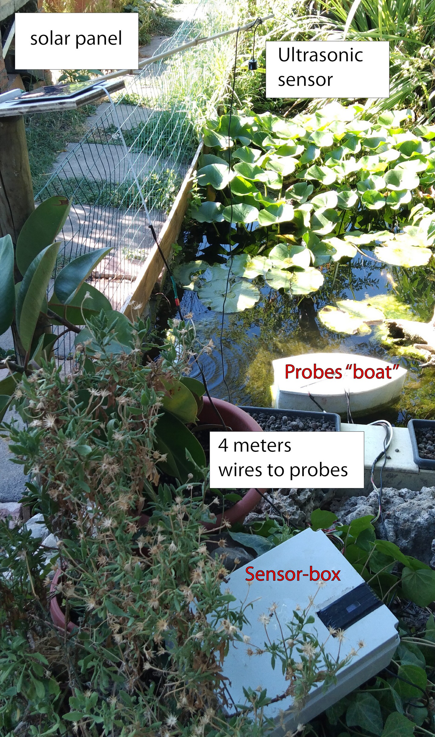
3The testing setup
This is the working test setup in a small artificial pond
![]() from another view
from another view![]()
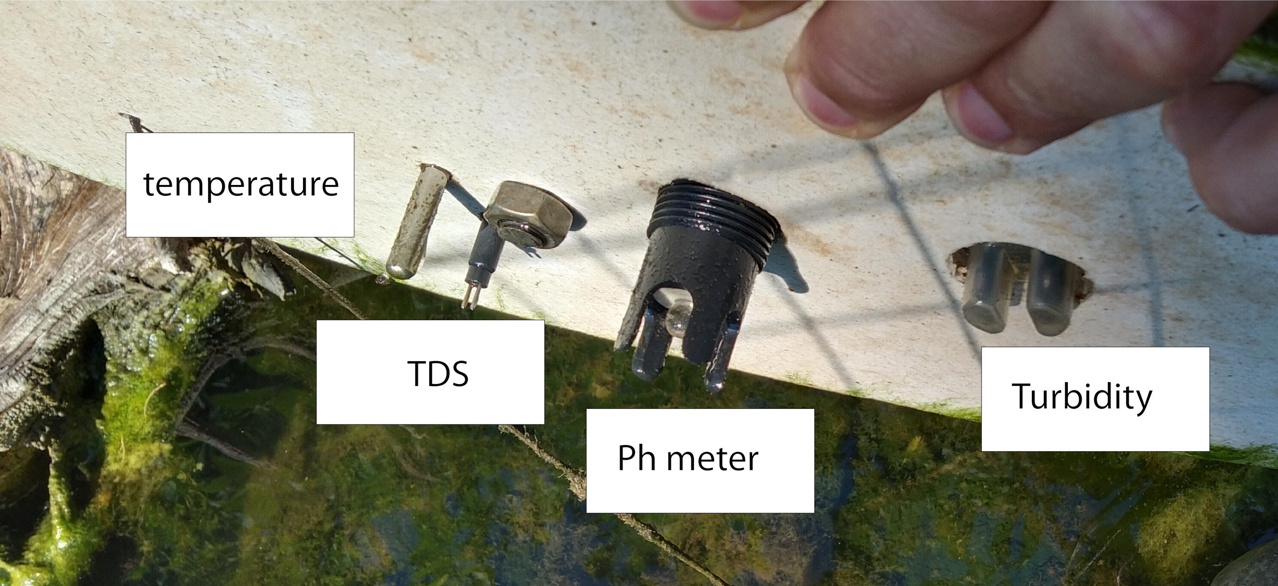
under the boat
![]()
the turbidity sensor in NOT... waterproof! why? a big work of self-amalgamating tape and silicone glue is needed to do not wet the circuits…
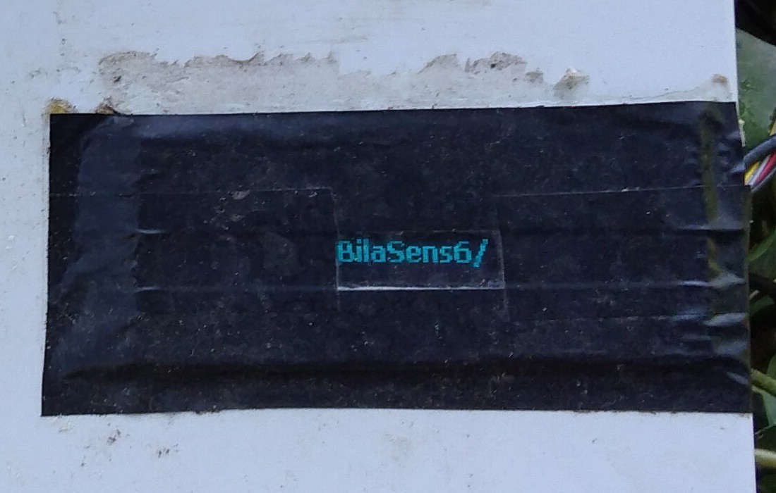
The "Splash screen"
![]()
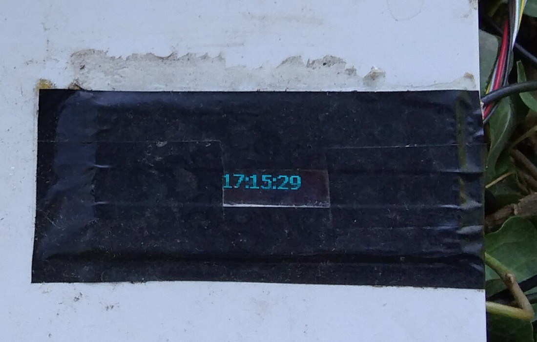
What time is it now?
![]()
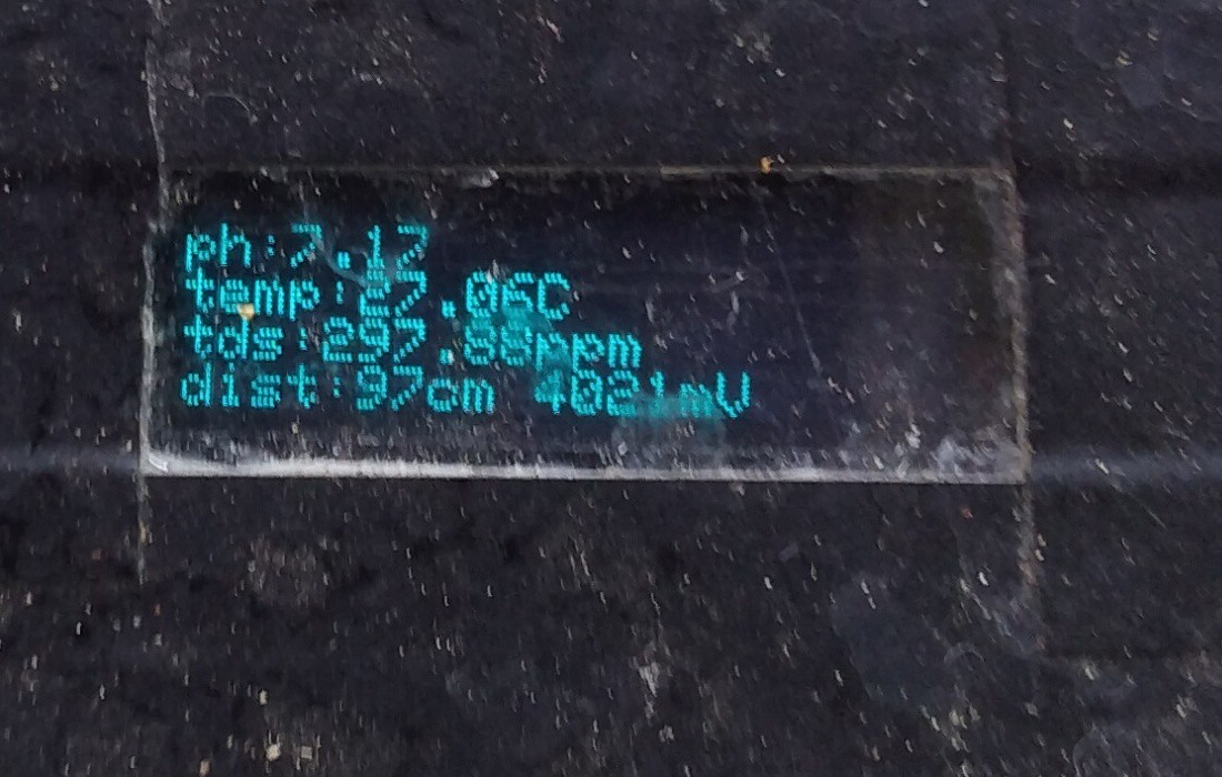
The readings on screen
![]()
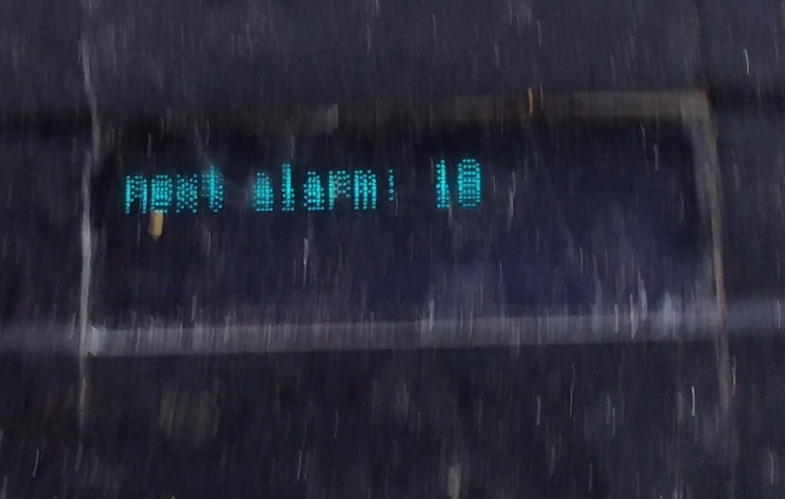
Next alarm (gsm sending) at...
![]()
Here you can see collected data "realtime"
(at now, 31 july 22) -
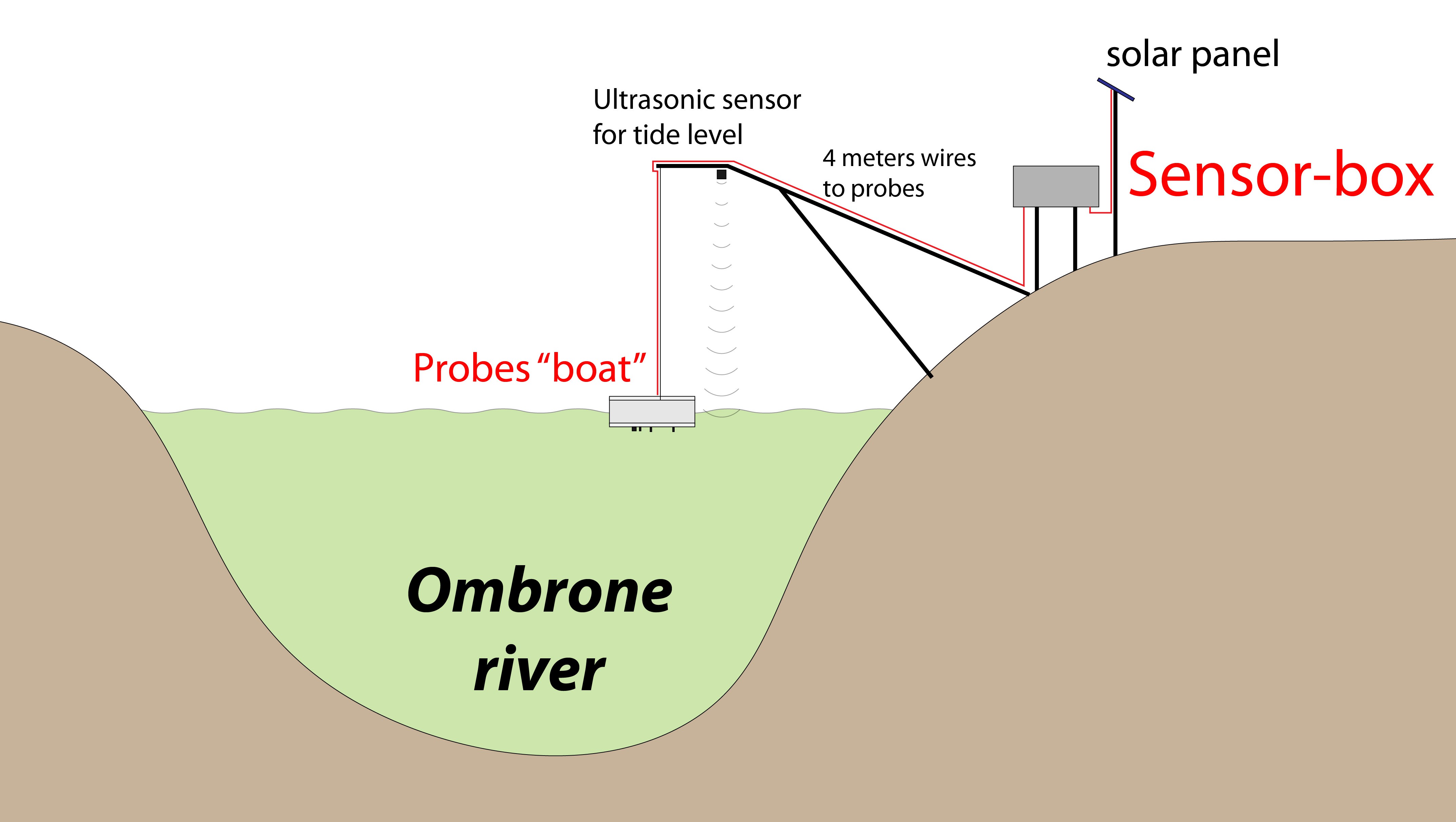
4The final setup (in progress)
here the project of the final setup... hope to see it catching data soon!
![]()
BilaSens: from river to the cloud
A multisensor that send data via GSM to thingspeak and show them on a small screen

 from another view
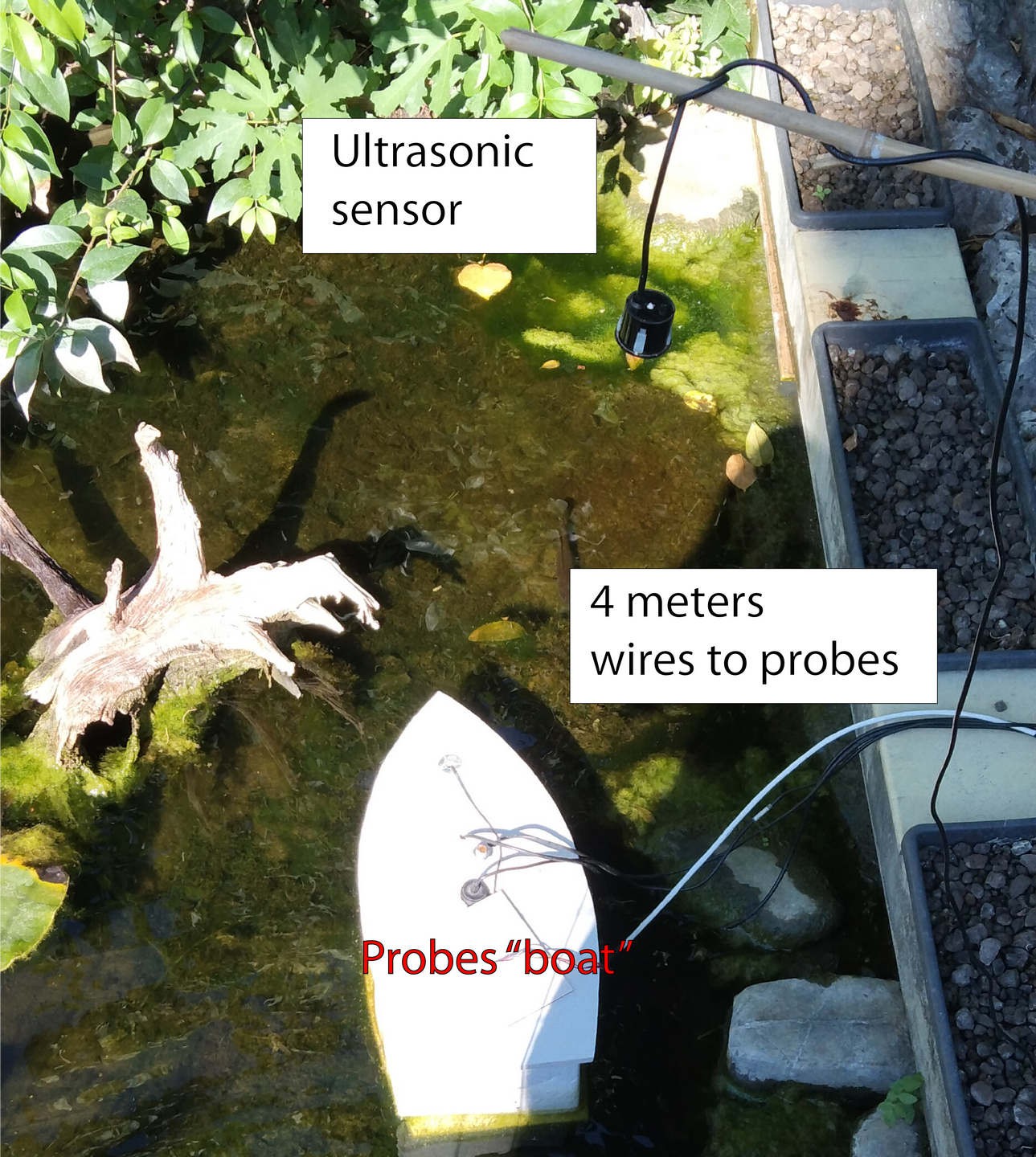
Discussions
Become a Hackaday.io Member
Create an account to leave a comment. Already have an account? Log In.