-
Op-Amp Update
05/10/2022 at 03:51 • 0 comments- Checked out op-amps recommended by https://tools.analog.com/en/filterwizard/:
- All IC's cost $5-10 for 1, contain 2 op amps per IC, all but one is surface mount, the one that isn't surface mount, LT1459 requires a supply current of one uA per op-amp and a min supply voltage of 2.2 volts... Would be perfect, but cost is too high, about $100 worth would be required
- Will use LM324:
- Single supply range: 3V-32V
- Dual Supply range: +/-1.5 to 16V
- Supply current: 1.5 mA (not sure if that's per IC or per op amp)
- 4 op amps/IC
- Price 1:$0.70!!!!
-
LM3915 Base Circuit
05/09/2022 at 00:55 • 0 commentsImported model of LM3915 Circuit that I found online https://www.electro-tech-online.com/threads/simulation-model-for-the-lm3915-logarithmic-bar-dot-display-driver.134305/ and made circuit model that will succeed the spectrum filters
-
Volume Meter IC and Adjacent Circuits
04/23/2022 at 21:18 • 0 comments- Looked into IC's will be
using LM3915, possesses
logarithmic scale, adjustable reference voltage and adjustable LED supply
voltage - LM3914 vs LM3915 vs LM3916 -
What are the differences?
- Manufacturer discontinued making it, have one vendor on prime that can get it to me next week Friday
- A precision (inverting) rectifier uses
op-amps to compensate for the voltage drop across the diode
- Correct amplification ration (R1:R2) for compensating the voltage drop due to the diode only good for a single |Vi| value
- If R1 = 10k, Vd = 0.7V
- Vi = 10, R2 = 10.7k
- Vi = 1, R2 = 17k
- A "superdiode" (precision non-inverting rectifier) can be used instead
- ***LM3915 has recommendations on what type of rectification should be used in the input signal, leaning towards precision full wave peak detector
- Looked into IC's will be
using LM3915, possesses
logarithmic scale, adjustable reference voltage and adjustable LED supply
voltage - LM3914 vs LM3915 vs LM3916 -
What are the differences?
-
Added Corrected Filters
04/21/2022 at 03:48 • 0 commentsMade spice model of remaining filters!!
- Low-Midrange Filter:
- Had to change Center Frequency input from 375 to 354
- Midrange Filter:
- Had to change Center Frequency input from 1250 to 1000
- Upper-Midrange Filter:
- Had to change Center Frequency input from 3000 to 2830
- Presence Filter:
- Had to change Center Frequency input from 5000 to 4900
- Brilliance Filter:
- Had to change Center Frequency input from 13000 to 11000
- Low-Midrange Filter:
-
Hardware Test, LM3915, Comparator LT001 and Filter Fixing
04/20/2022 at 03:50 • 0 comments- Added results of frequency test to Frequency Information excel file
- ***When headphones are connect to the Y-splitter while the oscilloscope is connect to the other port of the Y-splitter the max voltage of the waveform is reduced, interestingly enough, when I'm listening with headphones and have the oscilloscope connect or disconnected to the second port of the y-splitter it doesn't appear to affect the audio volume
- Simulated op-amp LED Ladder Display
- Seriously considering using the LM3915 Dot/Bar Display Driver IC instead of building my own LED display; less discrete components will be needed and will therefore save space, also can drive up to 10 LEDs
- When I want to build a comparator circuit with LTSpice, use op-amp LT001
- Am now using a 6th order Butterworth filter to isolate the Sub-Bass frequency spectrum
- For the Bass Filter, I entered in parameters: Center Frequency - 155Hz and Passband - 190Hz, the filter-wizard returned a 6th order Butterworth filter centered a 182.5 Hz with a Passband of 190, in order to get the passband that I desired I had to change the Center Frequency to 122 Hz. ***Will have to make similar fixes to the remaining filters
- Added results of frequency test to Frequency Information excel file
-
Active Filters
04/18/2022 at 03:48 • 0 comments- ****Classic RC filter attenuates too slowly, by increasing the order you also increase the slope in the passband, unacceptable, therefore will use active Butterworth filter - Sallen Key topology
- Found website that builds active filters for you based on design specifications: https://tools.analog.com/en/filterwizard/
- Have preliminary design for all music spectrums
- Bought mono-aux cable that splits into separate power and ground wires
-
Sub-Bass Isolator and Rectifier
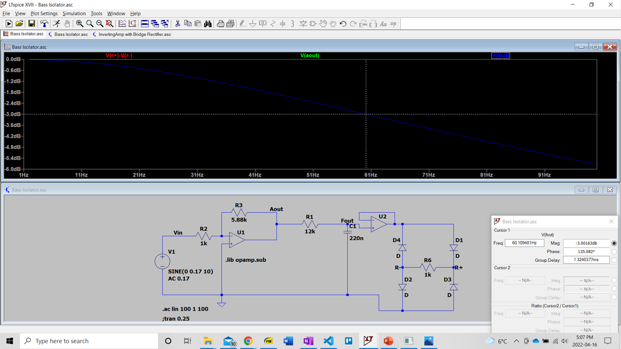
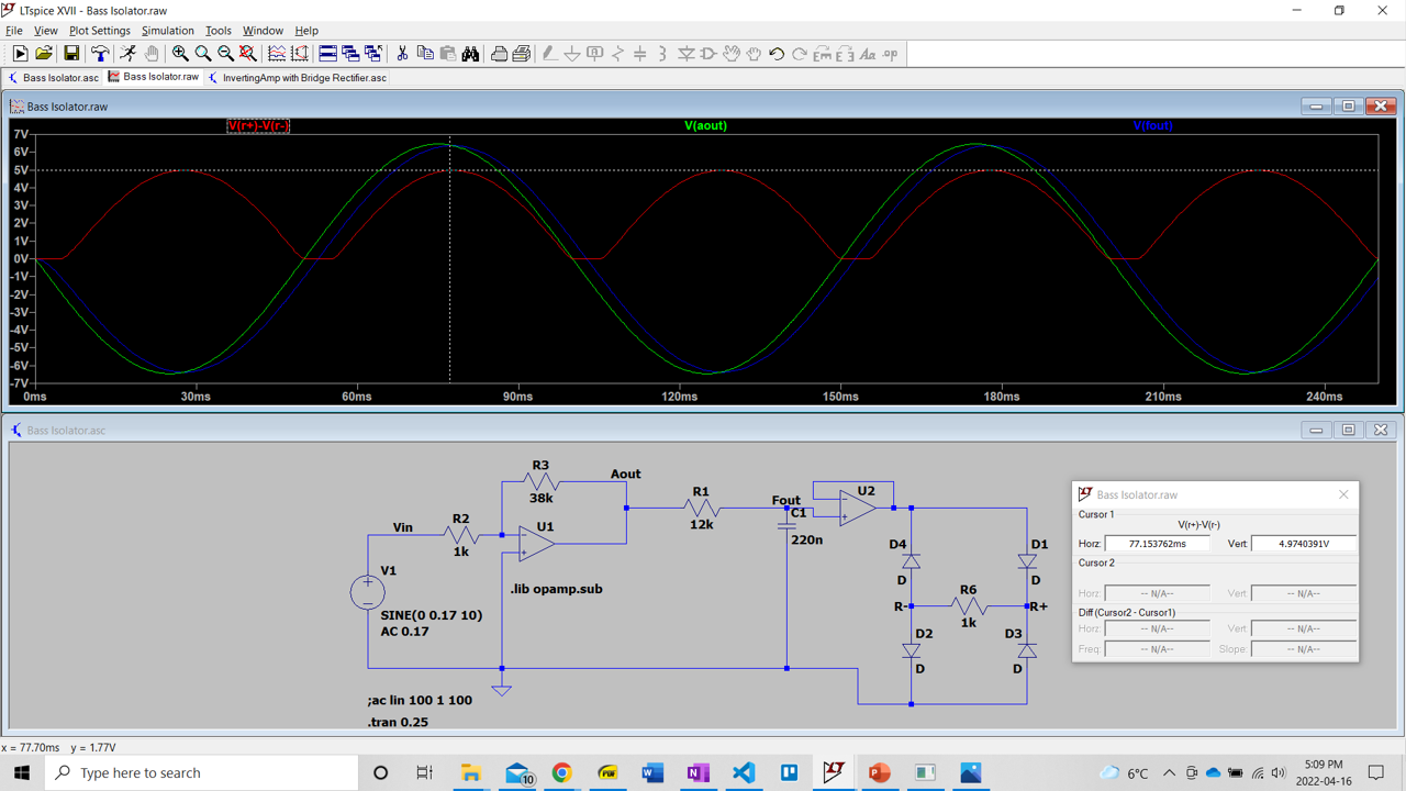
04/16/2022 at 21:45 • 0 commentsCreated preliminary circuit for isolating the sub-bass frequencies from the headphone port, here represented by V1
The first part of the circuit is the inverting amplifier. It amplifies the raw voltage from the headphone jack. As of now this will be common for the entire music visualizer circuit.
The second part is the low pass filter, the cut of frequency is about 60Hz. Because this is a single pole filter it attenuates the signal at -20dB/decade, this is too slow as it doesn't attenuate the Bass frequencies enough, will have to use a higher order filter.
The last part of the circuit is the voltage rectifier. The first part of the rectifier is the voltage follower, it isolates the LPF from the bridge rectifier, therefore the bridge rectifier doesn't affect the frequency response of the LPF.
Below shows Magnitude Bode plot form 1 to 100Hz
![]()
Below is transient response with a sine of 10Hz and an amplitude of 0.17V
![]()
-
Output of Computer Audio Jack
04/09/2022 at 05:51 • 0 commentsBookmarked an online tone generator website: https://www.szynalski.com/tone-generator/
- Used scope to measure output voltage of aux cable
- When sound player (Spotify, YouTube, online tone generator etc) is at 100 percent and computer audio set to 42, peak-to-peak voltage is about 0.34V
- When sound player (Spotify, YouTube, online tone generator etc) is at 100 percent and computer audio set to 100, peak-to-peak voltage is about 1.6V
-
High Level Plan
03/26/2022 at 23:57 • 0 comments- Will have 5 decibel ranges for volume, if frequency band is above lower limit for that range, associated LED will turn on
- LED Colors (from low to high volume)
- Blue
- Green (Turquoise)
- Green
- Yellow
- Red
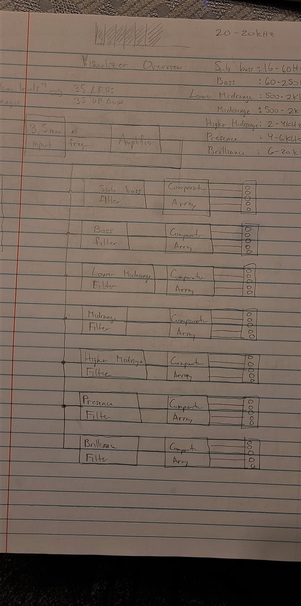
- Spectrum & Db visualizer steps:
- Connect to sound source via 3.5mm jack
- Pre-amp the signal voltage
- Split up signal into 7 frequency ranges using array of bandpass filters
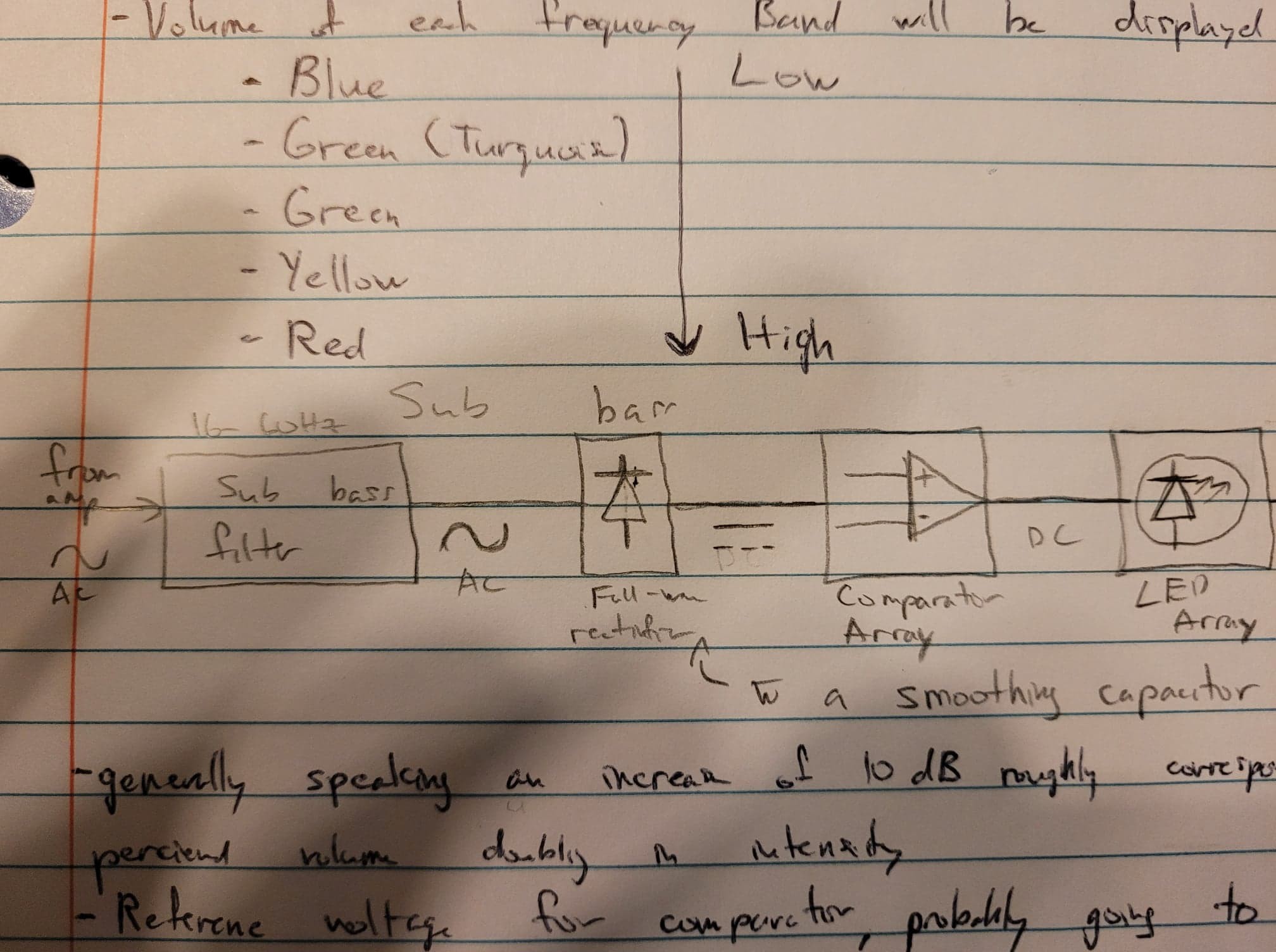
- Each filter will be followed by a (bridge) full-wave rectifier with a smoothing capacitor filter
- DC signal from rectifier will be fed into an array of comparators
- Each comparator is followed by an LED circuit, if the DC signal is higher than the reference level, the LED will light up
- Reference voltage used for comparator circuit will probably be made adjustable
![]()
![]()
-
Research
03/26/2022 at 23:45 • 0 commentsMusic is divided into 7 frequency spectrums:
- Sub-Bass: 16-60Hz
- Bass: 60-250Hz
- Lower Midrange: 250-500Hz
- Midrange: 500Hz-2kHz
- Higher Midrange: 2-4kHz
- Presence: 4-6kHz
- Brilliance: 6-20kHz
Generally speaking, an increase of 10dB roughly corresponds to the perceived doubling of intensity
Max output voltage of a 3.5mm jack doesn't seem to have a standard limit, will have to figure it out experimentally
Music Spectrum and dB Visualizer
Receive input from a 3.5mm jack, divides the music into 7 frequency bands, shows the loudness of each frequency band in DB using LEDS.
 Ghani Lawal


