-
Case Design
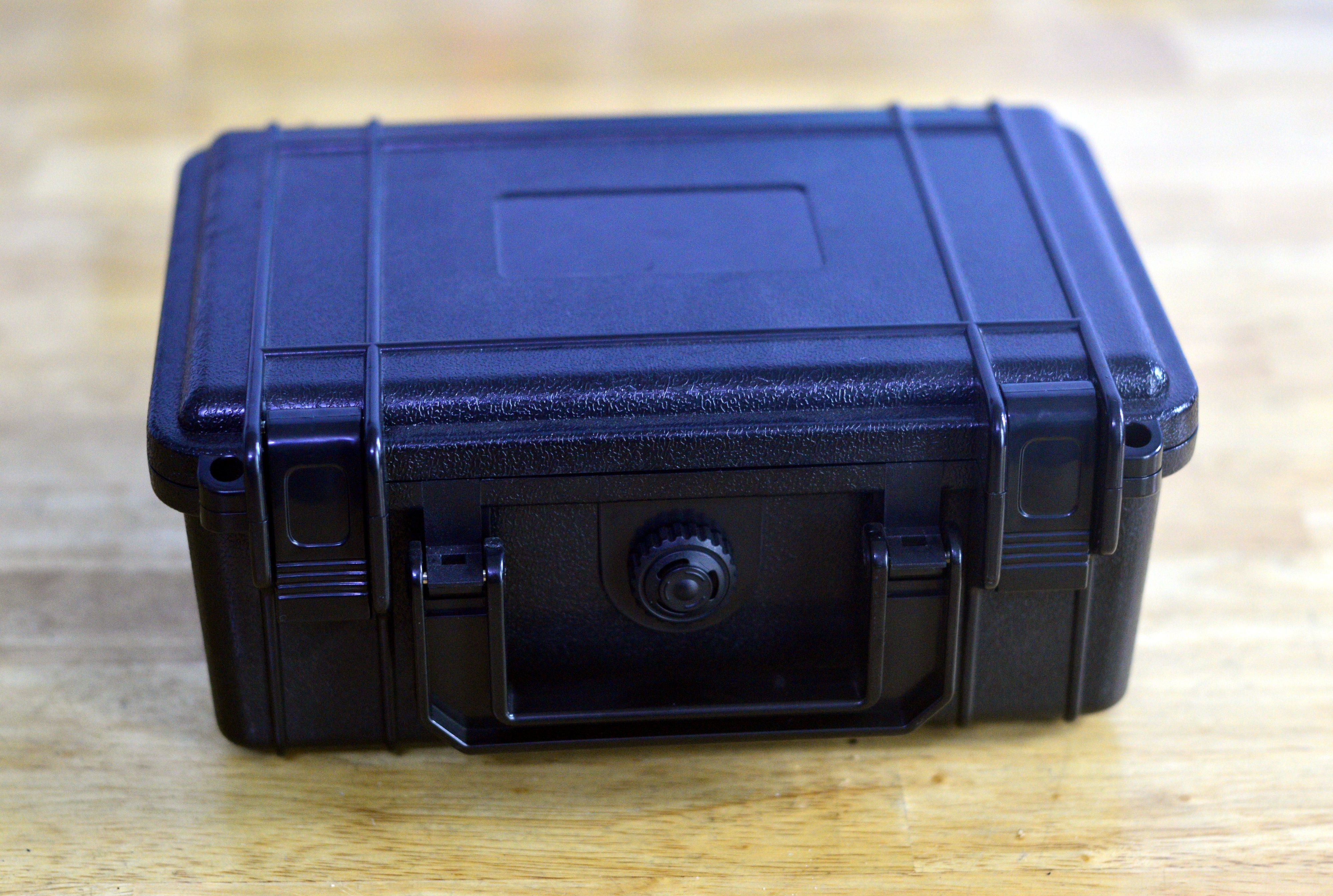
04/11/2022 at 09:58 • 0 commentsI had bought a number of ABS enclosures for ground control stations and generally to carry client prototypes around. I had a spare one that didn't fit the stuff I wanted it to:
![]()
They are very good cases and it was a shame not to use it. I installed some banana connectors on the far side (not shown) to connect a variety of external power supplies.
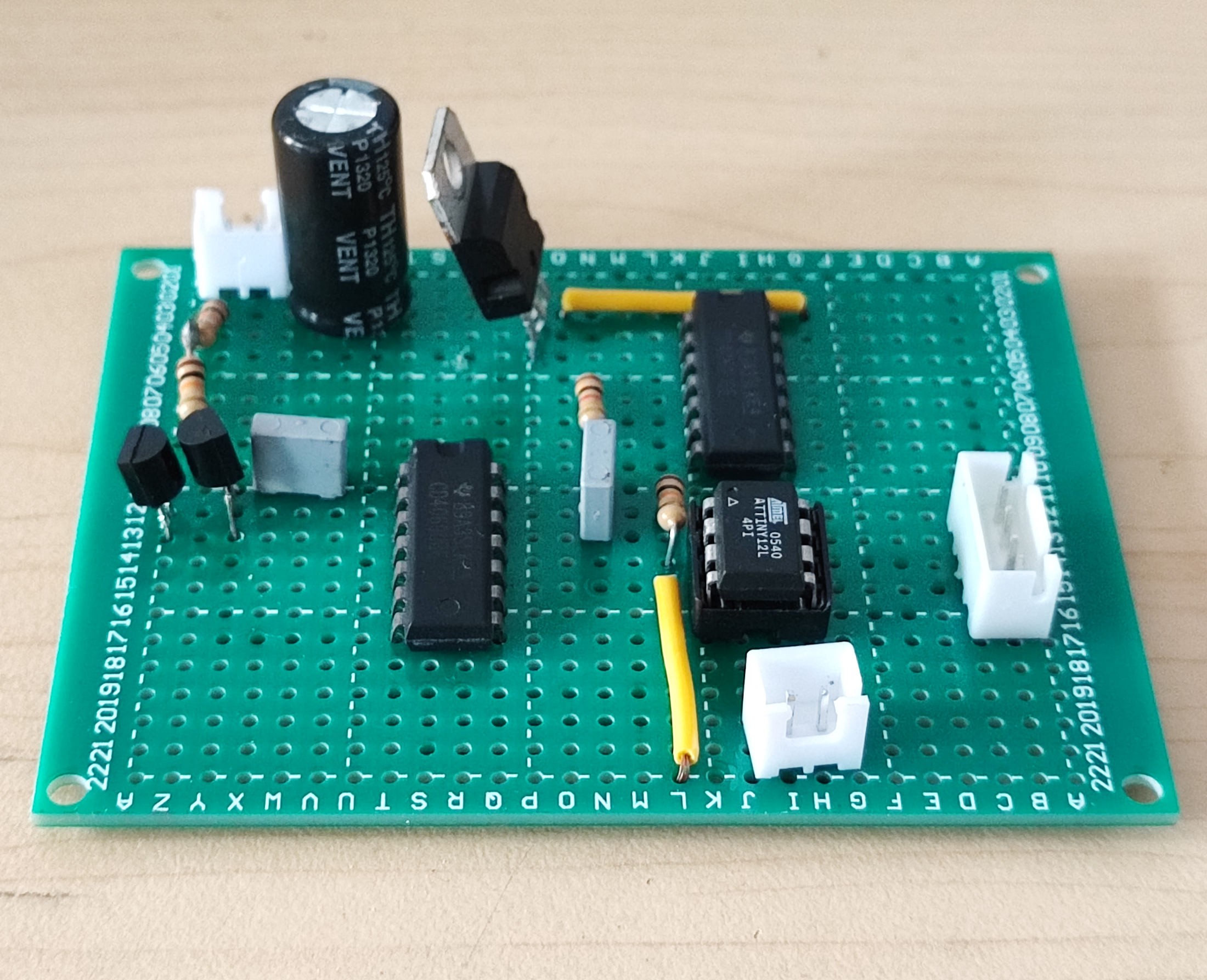
Inside, it is filled with foam scored in a grid pattern. You break off pieces to fit the part you want to store. In our case, we want to store a small piece of perfboard with our circuitry:![]()
The connector at the top is for power, to the bottom is trigger input, and to the right is output. In our case, we will connect the trigger input and the output to a control panel. I have tons of scrap brass panels around, leftovers from building various prototypes. One happen to fit!
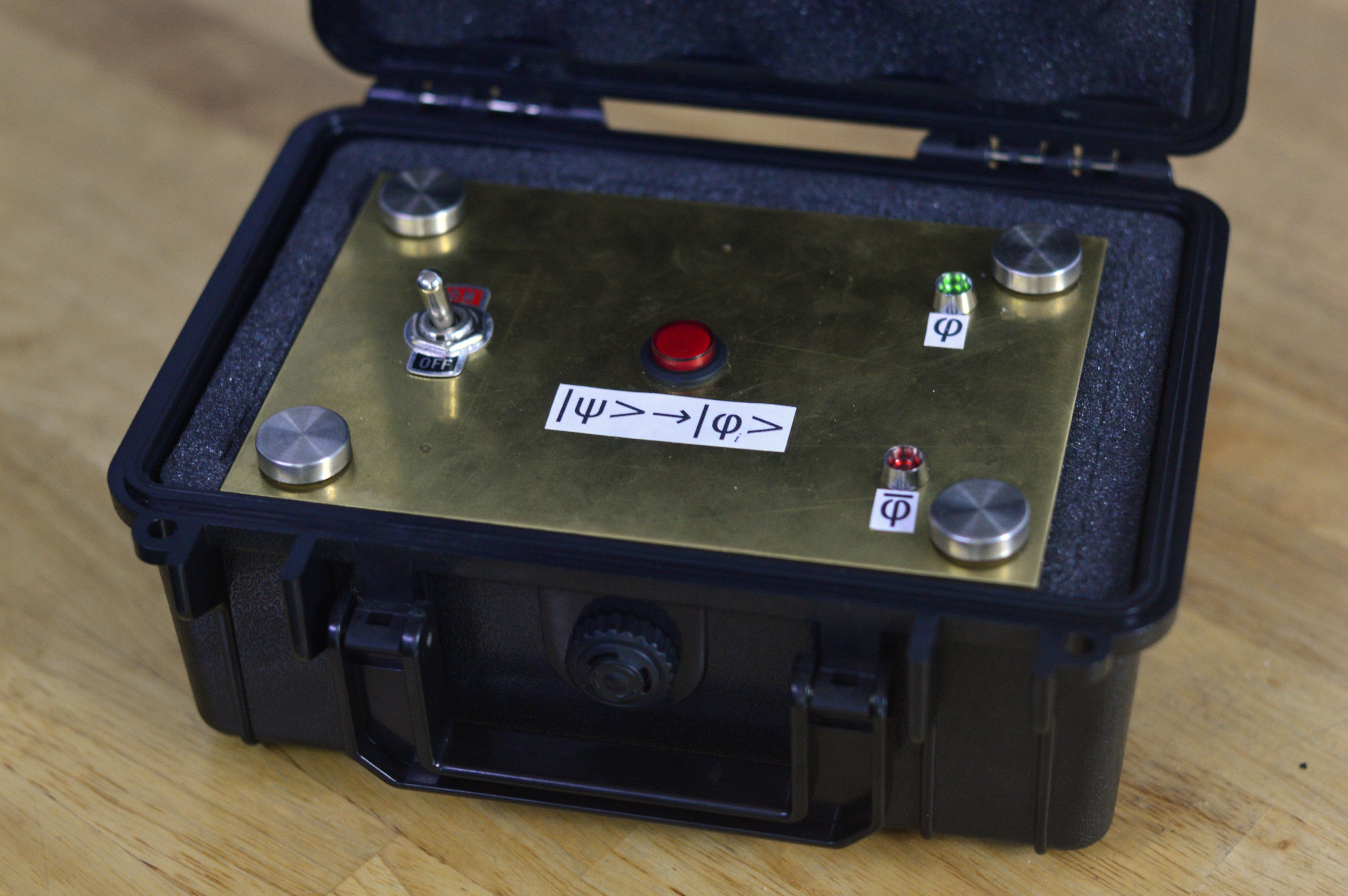
I dug through my parts bin for switches and flanged LEDs (I always have flanged LEDs). We're spoiled for choice when it comes to industrial switches in Vietnam, so I found some pretty good stuff. I drilled holes, mounted the parts, and it all fit in pretty well... except the panel would slide around when you tried to flip the power switch. I mean, of course -- It isn't attached to anything!
I had kept some mounting points for glass tabletops for the better part of a decade for some reason. They looked quite good, so I drilled holes in the corners and in they went.
These have a shaft that inserts itself into the foam, securing the panel in place reasonably well. The whole thing now looked quite decent, had a good weight, and good tactile feedback on all inputs!
![]()
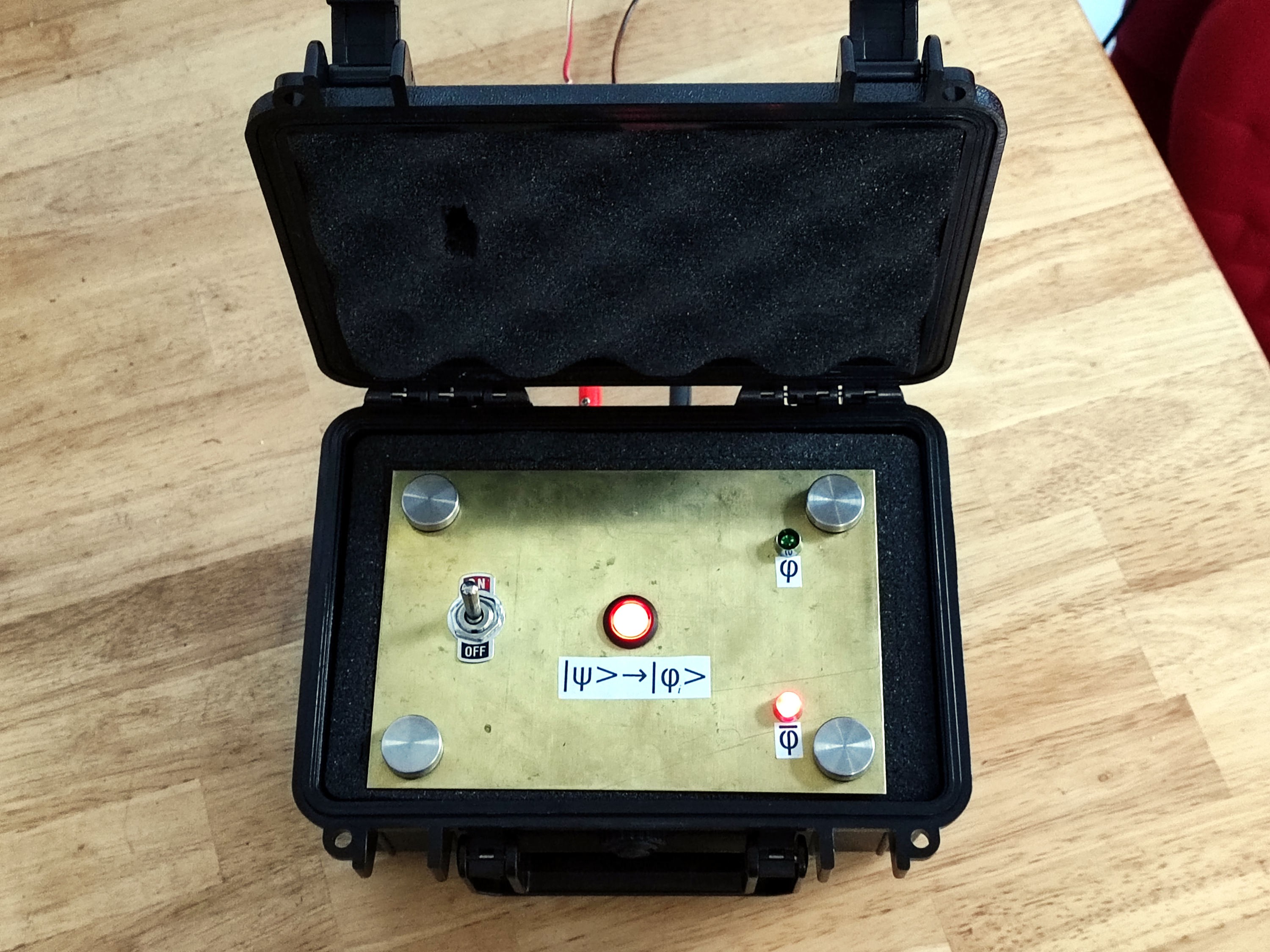
I finished up by adding some labels. I'm out of ferric chloride and solvent, so I printed up some stickers. The solution to the problem is always in the room!
For now, the output is simply connected to the control panel LEDs, however it's designed to be connected to another device one day. For now, this is fine though -- the button lights up nicely when active, and the flanged LEDs look good are lit clearly:![]()
-
The Post In Which I Reveal the True Nature of this Project
04/03/2022 at 06:18 • 0 commentsSome people might be inclined to ask about the performance of this device as an entropy source. This section is for you. Hello friends!
I rebuilt this device using a fancier ATMEGA16 clocked with a 20Mhz crystal, and used 3904 transistors to generate the quantum tunneling events at ~15V. I also used the 16-bit on-chip timer. This is to generate more tunneling events. The algorithm is the same except it accumulates entropy to an 8-bit register before serial output. That output goes to a MAX232, and then to my PC.I accumulated somewhere over 100 megabits of entropy and split it into 100 equal parts for analysis using the NIST Randomness Test Suite (https://nvlpubs.nist.gov/nistpubs/legacy/sp/nistspecialpublication800-22r1a.pdf).
I don't recall the exact test results (it was late at night, OK?), but they didn't reveal any obvious problems. I realize that *much* more evidence is required before you could call this system cryptographically secure, but for it's intended purpose, it should work fine.
...also I'll admit here that I might have lied a little about this device not being a joke. I mean, it's a real device that exists! You see, tying complex macroscale events (the name of this device) to quantum events, and them publishing it on a popular website is just my way of playing a little practical joke on anyone trying to simulate this Universe. It might not be that funny, but it is my first attempt at an interdimensional practical joke, so cut me some slack, don't be a tough crowd!
Anyway, there's your science fiction for the day. Or maybe just science. It was science fiction last week, anyway.
Oh, and if you're the programmer in our parent reality and read this, please don't respond here. Just encode something cool for us to find between the 23,074,248th and 23,075,235th hexadecimal digits of π. Maybe a picture of Waldo or something? Don't make it perfect though, add some noise to keep us guessing. -
Processing Stages
04/03/2022 at 05:41 • 0 commentsThis is where we convert a raw signal to a device that does something (questionably) useful!
I considered several ways to do this. At first, it had only a single output that would be either HIGH or LOW based on the observed state of the system on trigger input rising edge.Eventually, I realized a second output that is set to the opposite of the first output on trigger rising edge would be useful -- that way the device can be connected to two circuits down the line without extra components. I settled on this, and use a 4-pin connector to provide 5V, Ground, and the two outputs to whatever this gets connected to (coffee percolator or otherwise). I made the output latch for as long as the trigger is raised HIGH.
I also considered making it latch until a reset line is triggered, but did not implement this. My reasoning is that this device is most likely going to be connected to a toggle or knife switch, which of course provides mechanical latching! If I wanted it to work with intermittent switches (SET/RESET), I'd go back and add this feature. In case someone wants to do this in a hurry, the fastest way is probably to make the program NOP loop forever instead of going back to the start of the algorithm, then driving the RESET line of the MCU LOW via an intermittent pushbutton.
Anyway, back to the core algorithm. The full commented code is attached to this project. Overall, it's an implementation of a Von Neumann debiasing algorithm. You can read more about that here:
https://dornsifecms.usc.edu/assets/sites/520/docs/VonNeumann-ams12p36-38.pdf
If that link dies from bit rot, there's a formal reference at the end of this post.
In short, we start a timer when we see a tunneling event ending, and measure the time until the next event. Then we do it again, and measure the two times. The timer runs on something like 4Mhz +/- 1%, we just use the microcontroller internal oscillator because that's good enough here. If the first measured time is longer, we set the state ϕ = 1. If the second time is longer, we set the state ϕ = 0. If they are equal, we produce no output and try again until they are not equal.
Finally, we produce output. While the trigger input remains high, OUTPUT 1 is equal to the state ϕ, and OUTPUT 2 is always
¬(OUTPUT 1) -- in other words the opposite of OUTPUT 1. We wait idle while the trigger input remains HIGH.That's about it! Here's that reference I promised earlier:
J. Von Neumann, “Various techniques used in connection with random digits,” Applied Math Series, Notes by G. E. Forsythe, in National Bureau of Standards, Vol. 12, pp. 36-38, 1951.
-
Amplification and Buffer Stage
04/03/2022 at 05:27 • 0 commentsThe signal past the 0.1uF DC blocking capacitor is not very strong, so we need to amplify it. Normally, I would design something with op-amps -- but that would likely mean some form of dual-rail power supply, and parts that cost more than 30 cents -- but this is a *science fiction* contest, and a future where we can afford such luxuries sounds more like high fantasy to me.
So instead, we'll use hex inverters. I like the CD4096, and keep plenty around. They have 6 inverters per chip, which translates to 6 inverting amplifiers, excellent value for money! To make that happen, we just put a 100k resistor between the input and output of an inverter stage, creating a feedback loop. In this design, I use two stages this way.
For details on how this works, you can read more here: https://wiki.analog.com/university/courses/electronics/electronics-lab-20
Overall, this is not only economical, but the resulting amplifier has reasonable bandwidth!
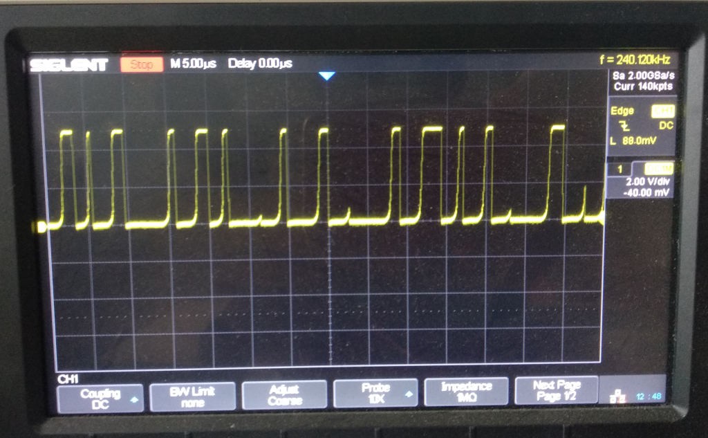
After two stages of amplification, the resulting signal has a maximum amplitude of around 5v and a slight DC bias. We remove that bias with another 0.1uF capacitor, and pass it though a 1k resistor before entering the buffer stage.The buffer stage consists of another hex inverter that shares ground with the rest of the circuit so far, but has a regulated 5V supply. This is to ensure that the signal never has a voltage that the microcontroller cannot deal with. We pass it through 2 stages of the hex inverter (no feedback resistors). This both provides a safety margin for our microcontroller (I only had the one unit left), and shortens the rise and fall times for our signal, making it a fairly clean square wave.
With that, we've converted quantum tunneling events to a signal that can be easily processed by a microcontroller! Below is an image of how that looks, any apparent pattern is an artifact of the small sample size:
![]()
-
Quantum Tunneling Event Generator
04/02/2022 at 04:48 • 0 commentsThis is the interesting part of the device! Before we launch into the specific implementation, I realize a little background might be useful.
Some of you may have heard of the Heisenberg uncertainty principle. A good summary is here: https://www.physicsoftheuniverse.com/topics_quantum_uncertainty.html
To summarize that summary, imagine trying to view an electron in a microscope. It doesn't matter what the magnification of your microscope is, you won't be able to see an electron using visible light. The ability of light to resolve objects depends on its wavelength -- if what you are trying to see is smaller than the wavelength of the light you are trying to bounce off it, you're not going to have much luck and it will not be visible.
We can imagine using higher frequency light though, right? To resolve an electron, we'd need very high frequency light called gamma rays. This replaces our previous problem with a new one: gamma rays have are powerful enough to significantly increase the energy of the electron we're trying to observe, increasing its momentum. The very act of measuring the electron's position requires that we change its momentum -- we cannot know both at the same time.
It turns out this is true in general (we cannot simultaneously know the position and momentum of anything), however the effect size is only noticeable for very small things.Where this becomes relevant to us, is that the momentum of an electron is typically measured in 'electron volts' or eV. One eV is the energy imparted on an electron by a potential difference of one volt. In our Event Generator, we are using a 10V power supply, so we know the momentum of the electrons should be close to 10eV.
Since I know that with some level of accuracy, that means I can't know exactly where the electrons in my circuit are. The semiconductor junction in my circuit might be rated for, say... 100V, but it also has a defined width! If it's narrow enough, sometimes the 10V electrons I would expect to be on one side of the junction are actually on the other side!
How did they get there? One proposed mechanism is that they 'borrow' energy from the environment via virtual particles, and 'pay it back' once they are on the other side. An even weirder debate is how long it takes to happen -- with several estimates being significantly faster than the speed of light (while I'm skeptical, this isn't prohibited unless it can transmit information, see apparent speed for more information).
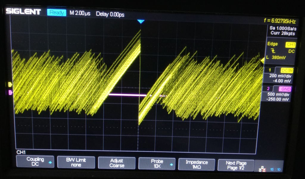
In any case, it happens and we can measure it. The signal is rather unique looking! It's characterized by a sudden change in voltage when the tunneling event occurs, followed by a decay. If you set your scope settings just right, the noise pattern looks really neat!
![]()
The signal does have a pretty big DC offset compared to its amplitude though. So besides providing a suitable junction for electrons to tunnel across, we also filter out this DC offset using a 0.1 uF capacitor.
Note that I've presented the explanation for tunneling that seems most intuitive to me. There are other ways of thinking about it (e.g. with waveforms). It's a nice Wikipedia rabbit hole if you don't mind your afternoon vanishing.
-
Power Stages
04/02/2022 at 04:00 • 0 commentsThis is the simplest, least-exciting stage, so I'll just add a couple of supplementary details.
The device needs a variable 10-15VDC supply. This is so you can adjust the frequency and amplitude of tunneling events -- too low a voltage and you'll get only a few, weak events. Too high, and the timer on your microcontroller won't run fast enough to easily measure the time between events.
Overall, the exact semiconductor you use has a bigger effect on tunneling frequency, but it's still nice to be able to tune it a little. Also the first hex inverter responsible for amplification can run a little hot at higher voltages. It's a pretty rugged part though.
I found around 10VDC worked fine for me -- that put the average time distance between events as a few microseconds (say 4), and I'm running the microcontroller at 4Mhz. However in another similar device, I used a 20Mhz microcontroller and pushed the voltage up to about 15V to improve performance somewhat.The 5V linear regulator is just there to power the microcontroller and signal buffer. We buffer the signal with a second hex inverter to give it better defined rising and falling edges, and also so that the signal cannot ever exceed 5V. I chose a linear regulator instead of a switched one because this is not a battery powered device, so the extra power cost is not really relevant, it is cheaper, and it produces less noise.
Schrödinger's Trigger
Using the joy of electron-tunneling, this device drives one of two outputs when triggered.