Close
0%
0%

TARDIS Themed Board Game Cabinet

Board game cabinet with a Doctor Who TARDIS theme with door sensors, LED strips, roof light and sound

Similar projects worth following
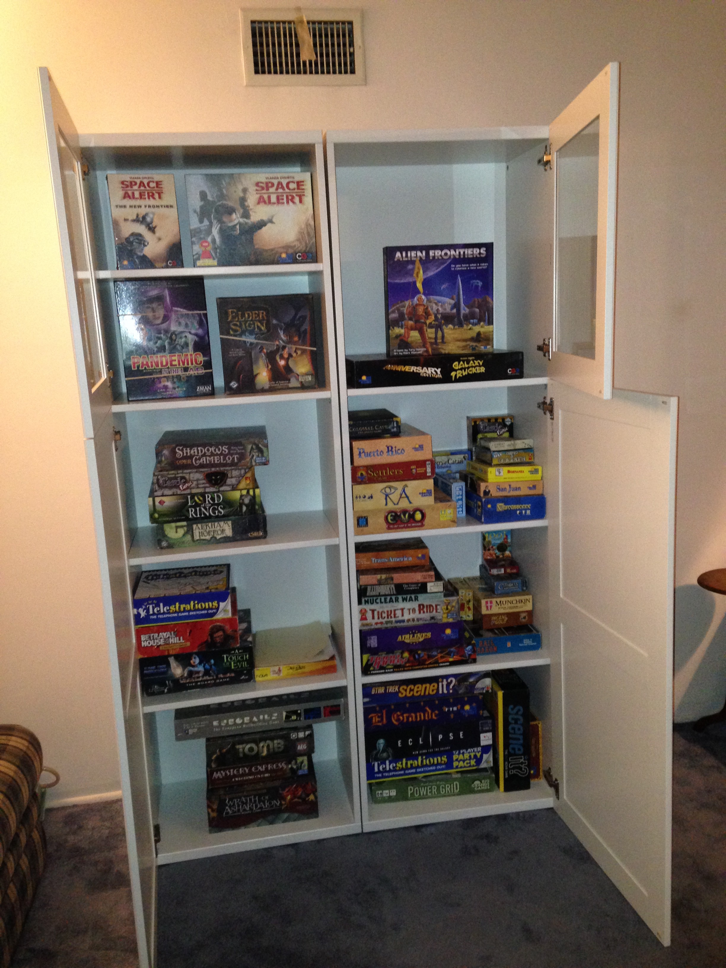
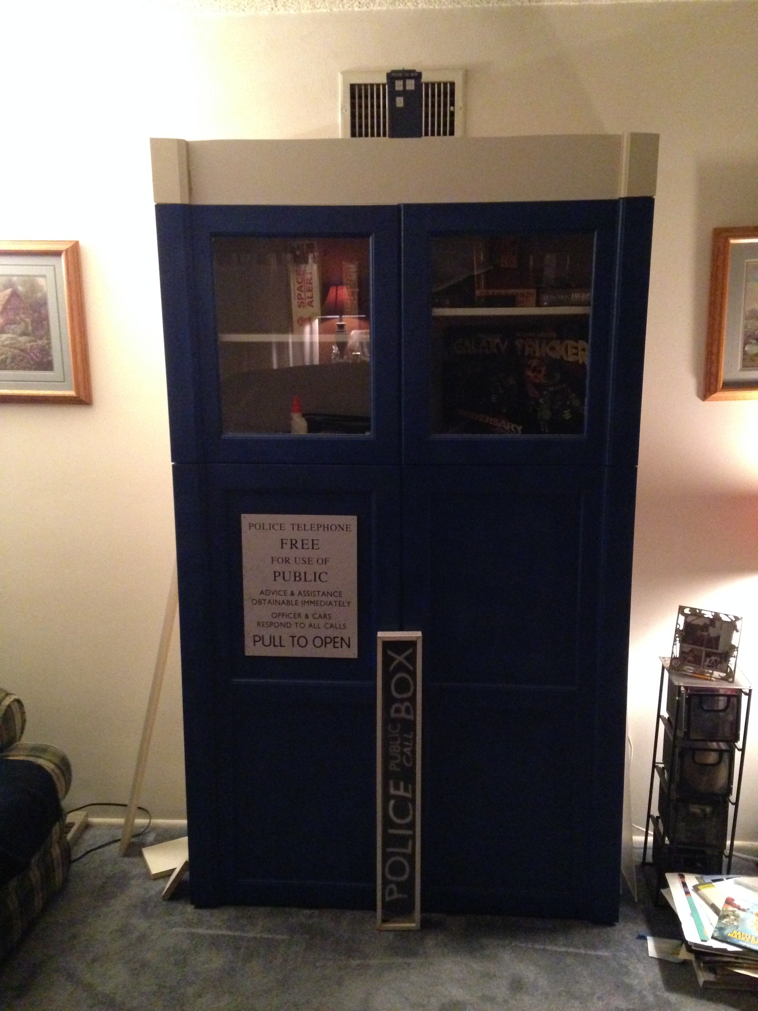
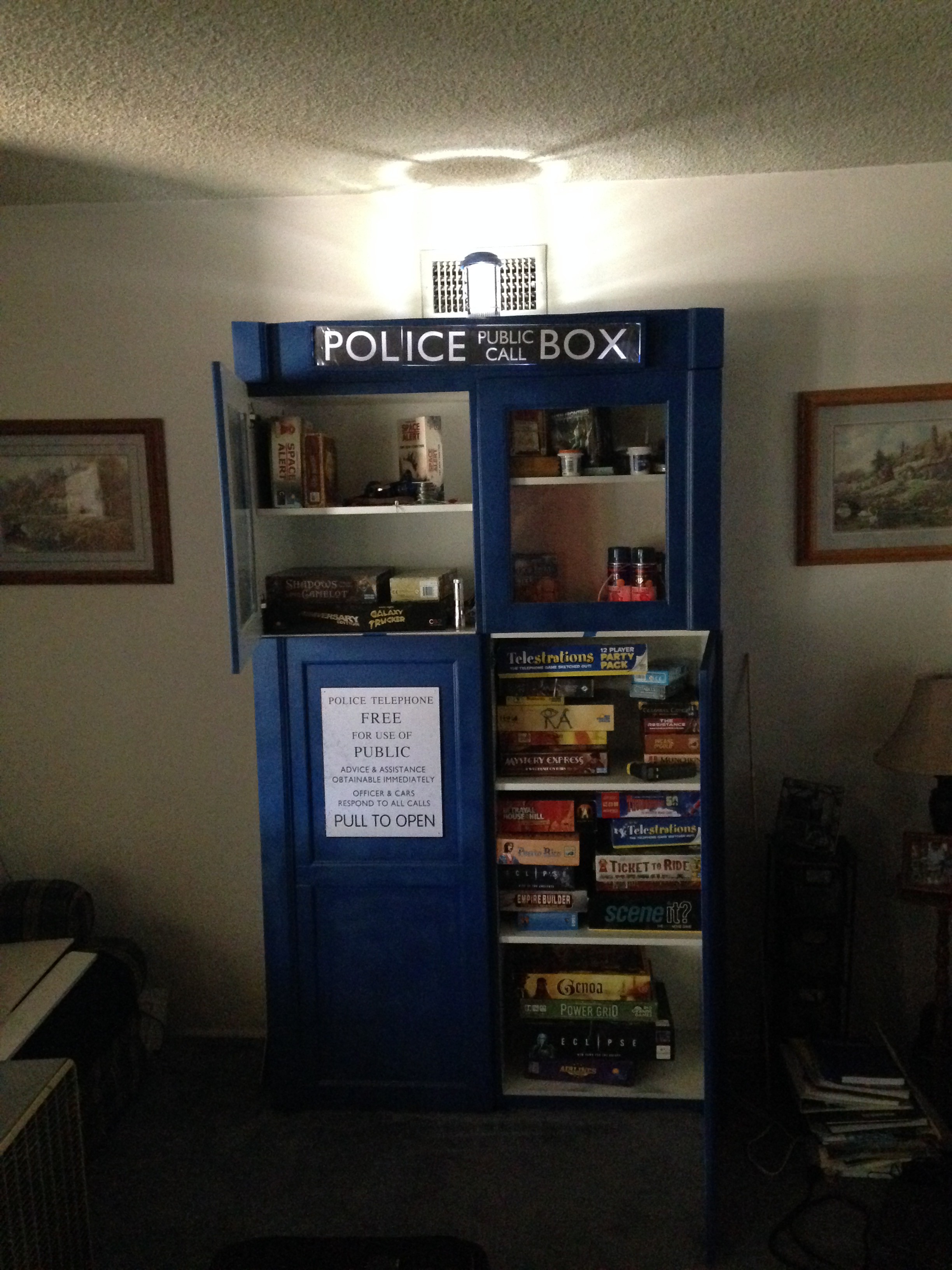
We needed a better way to store our board game collection and after looking around at several furniture and home improvement stores I got the idea to make it look like the TARDIS from the British science fiction TV series Doctor Who. We started with a pair of bookcases from IKEA, painted it blue and added the signature "Police Public Call Box" sign on top. Over the years I added lights and sound effects that are triggered by door switches. When we ran out of space I knew I had to make it "Bigger on the Inside!"

[Update 2023-01-12]
Resumed coding, migrated code repository on sourceforge from SVN to GIT.

https://sourceforge.net/projects/arduinotardis/

2014 - Birth Of A Game Cabinet

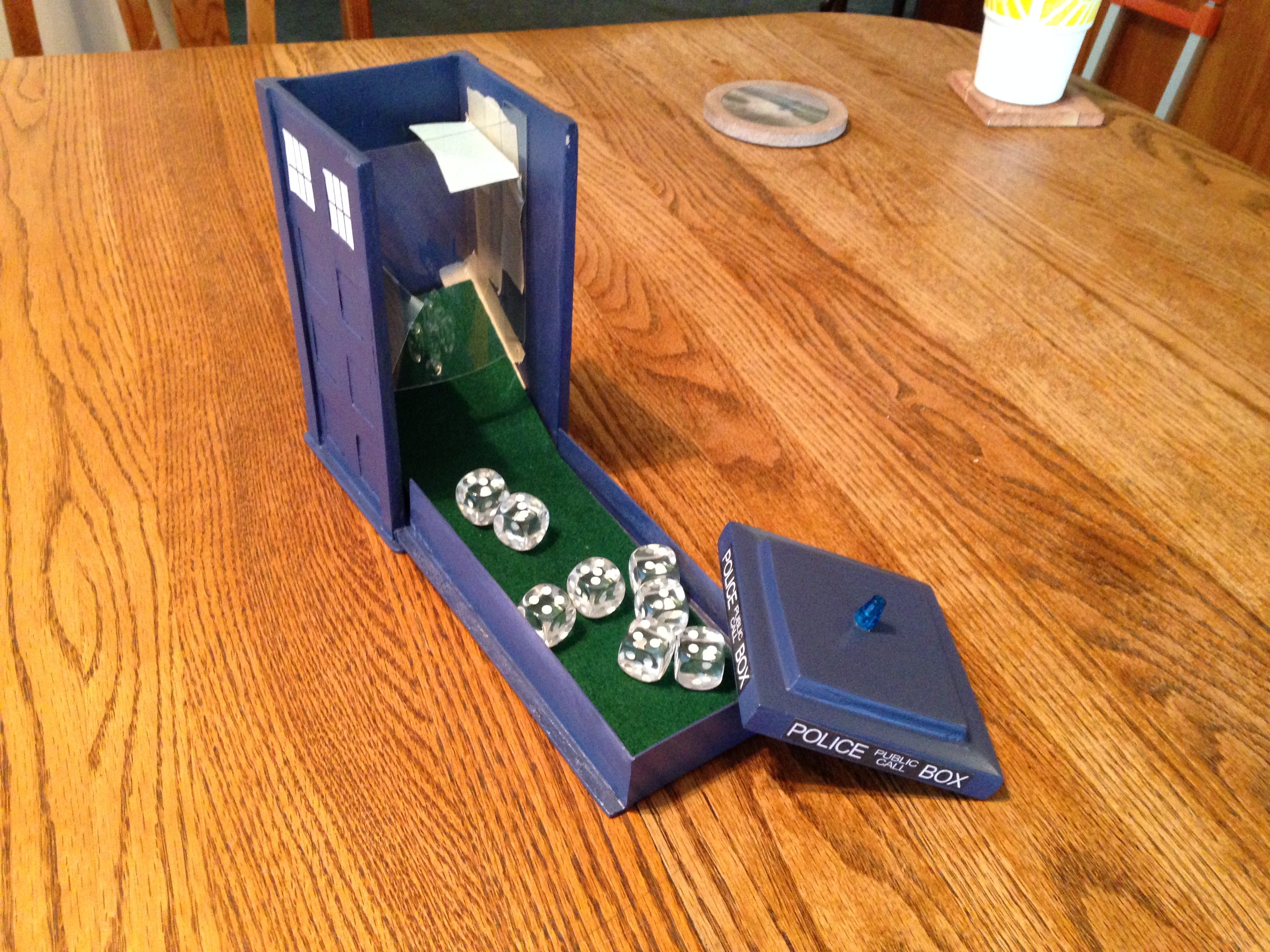
Our game collection was stored in various milk crates and other storage chests throughout the house. My wife suggested shopping around for a tall cabinet and after looking around I started to get an idea.  I had made a TARDIS themed dice tower and thought we could do something similar.  
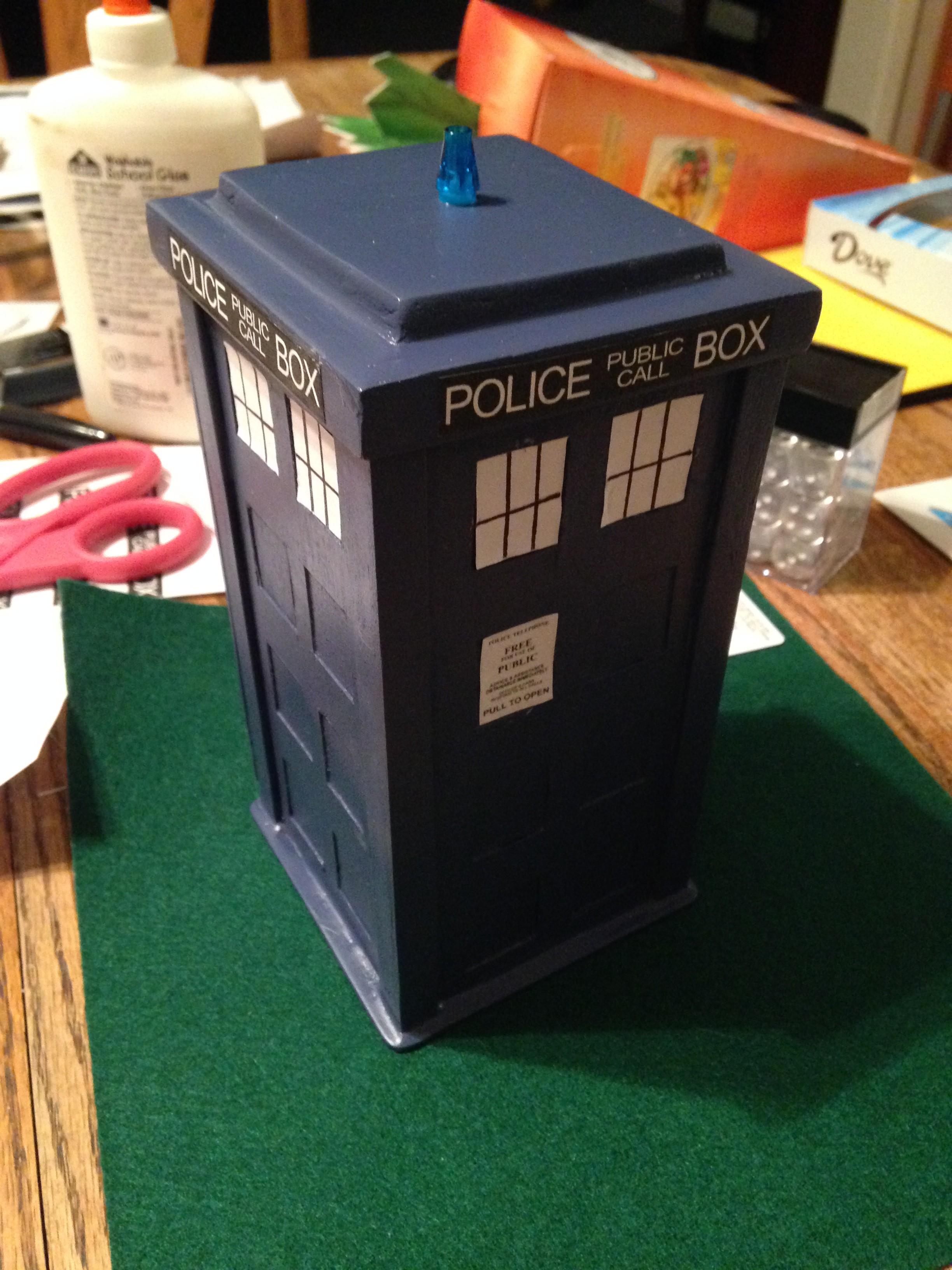

Some of the cabinets we looked at looked very nice but we didn't want to spend a lot if we were going to repaint it.  Found some cabinets with doors at IKEA that looked like they might work.  Measuring approximately 24" wide by 16" deep by 76" tall we picked up a pair so we could put everything in a single place.
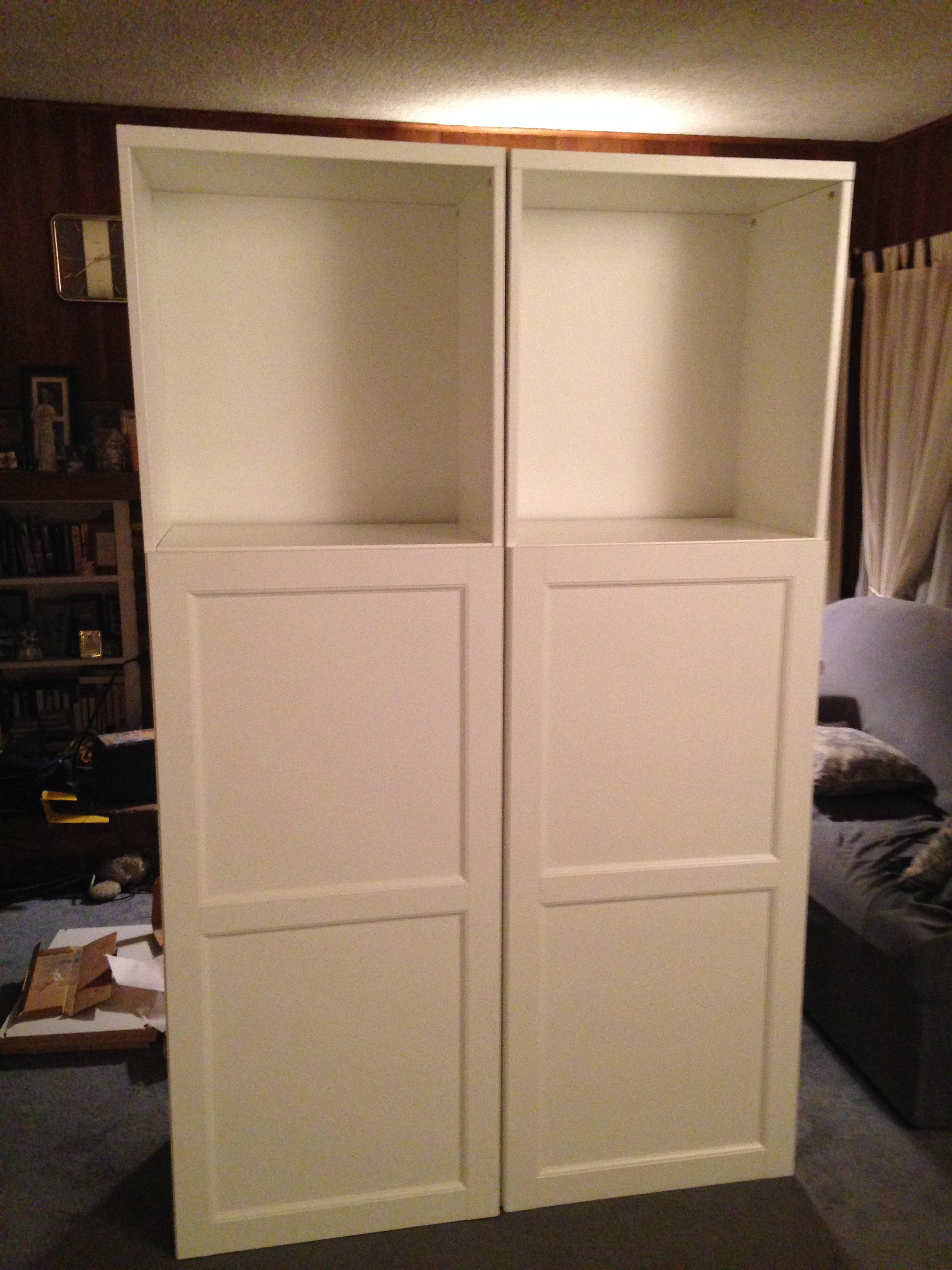
I made a box frame for the "Police Public Call Box" sign with a slot for the plexiglass.  The print itself is just a couple of pages from a laser printer taped together.  I also added some extra trim on the doors to make it look like corner posts and added a facade on top to hang the sign.  Royal blue seems close enough.  My wife found the plaque online somewhere. 

From the side it looks like a TARDIS has materialized partially into the wall.


2015 - Adding Lights And Sound

Started experimenting with different ways of lighting the sign.  Tried an electrolumenscent light strip but it wasn't bright enough so starting looking at RGB LED light strips using MOSFETs controlled by an Arduino Uno.  I used a 1 meter long non-addressable LED strip as the addressable strips were still pricey at the time and I wasn't sure how it would look.  The strip is driven by 3 MOSFETs which are controlled by 3 PWM output pins from the Arduino.  I started writing some code to fade the colors on and off giving it a pulsing look.  I was pretty happy with how it looked.  See below for some videos and the logs for some code snippets.

LED RGB strip from SparkFun

N-Channel MOSFET 60V 30A from Sparkfun
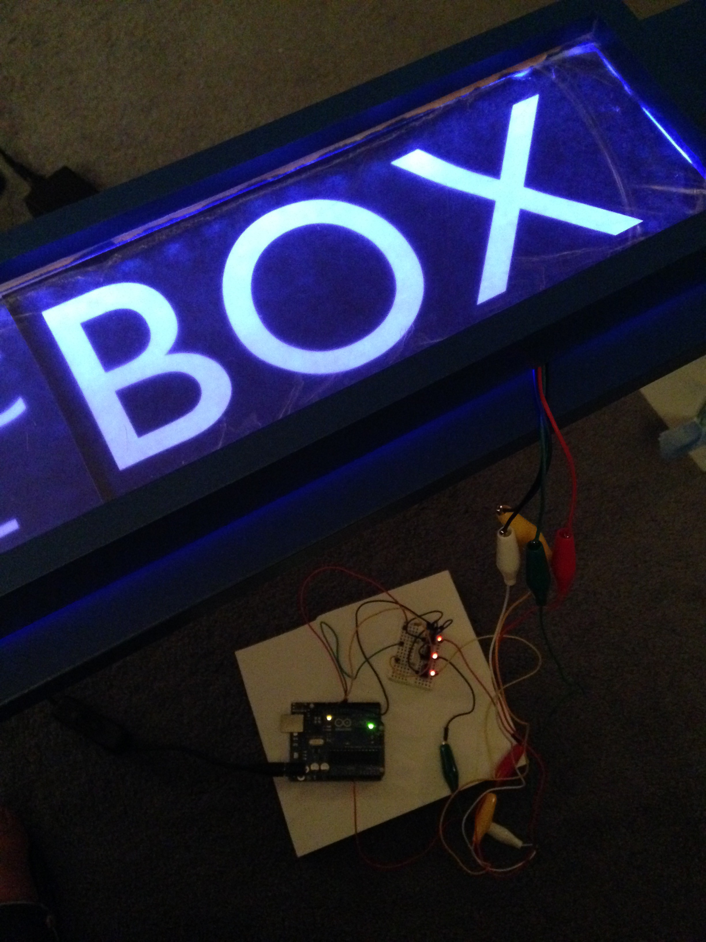
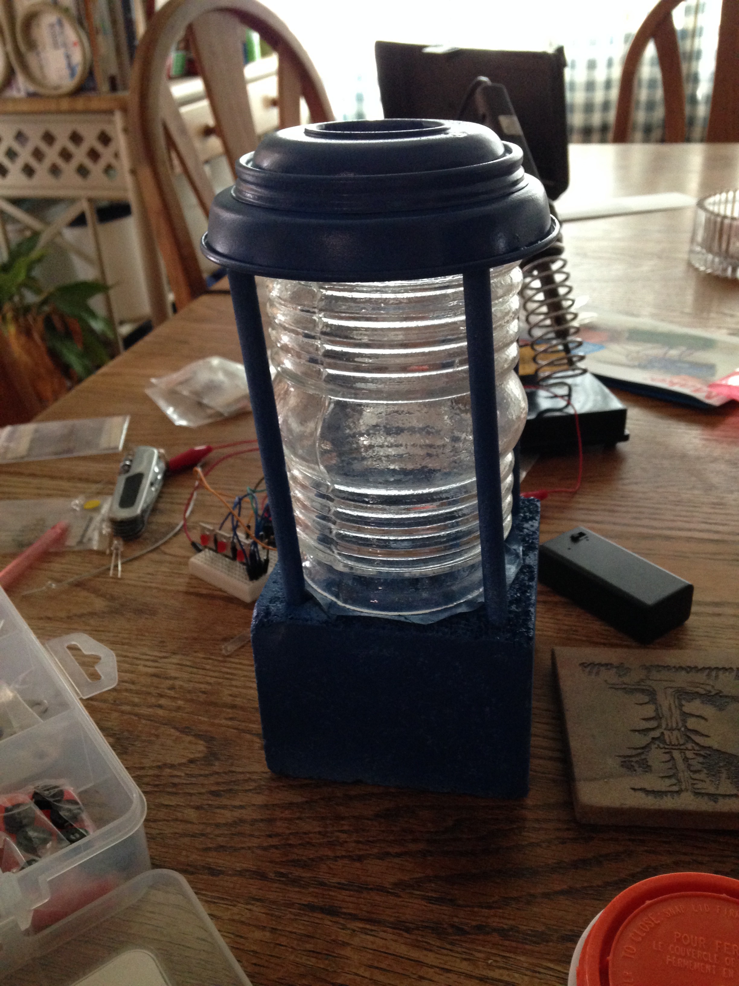
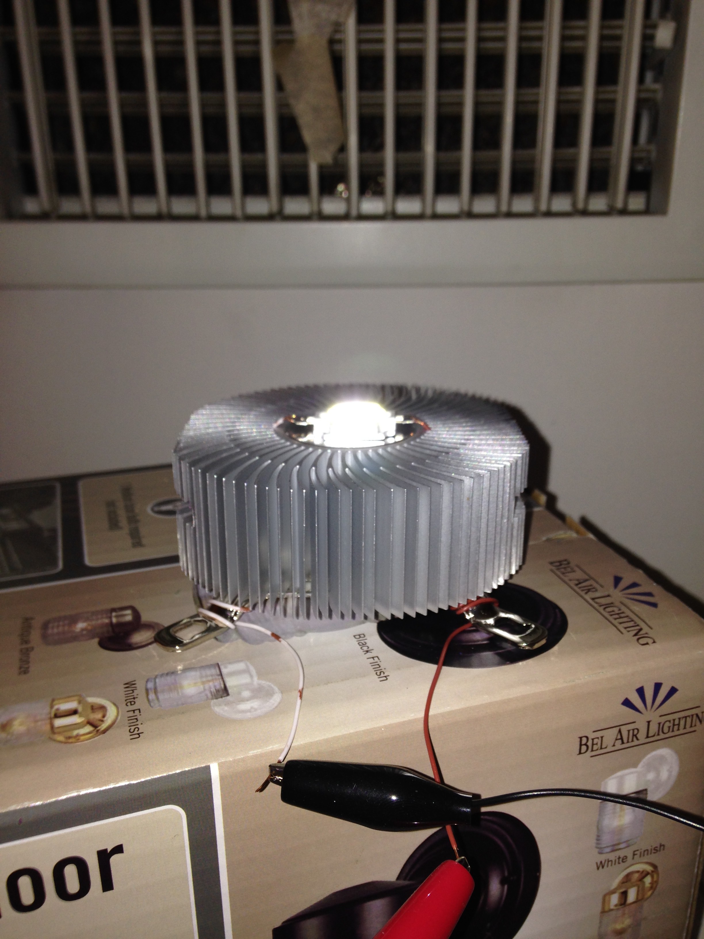
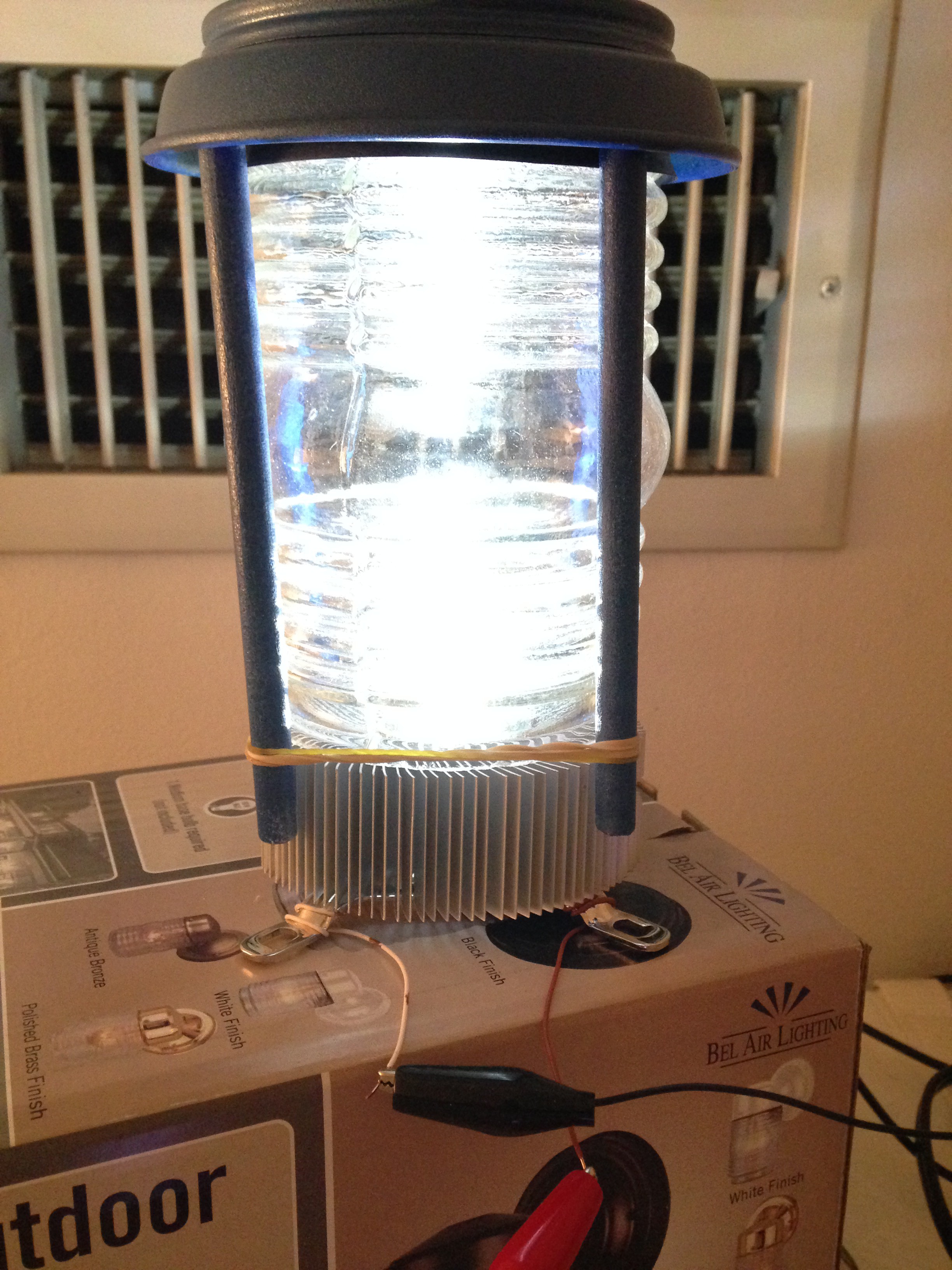
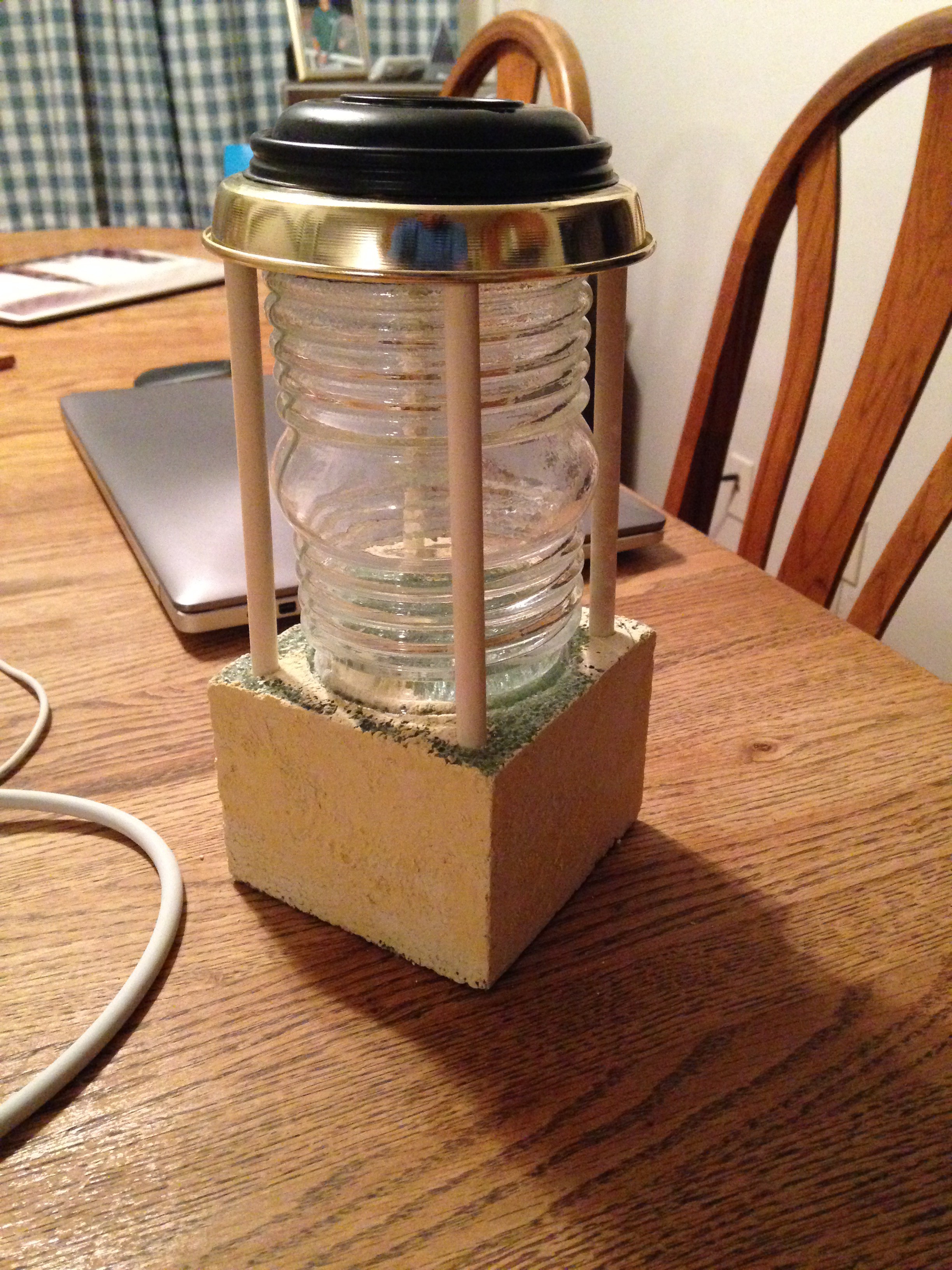
Also started working on the roof mounted beacon lamp and tried various ways to light it.  I first tried stringing a bunch of LEDs but didn't like the way it looked so I found a high intensity LED array that worked quite nicely but it need quite a bit of power which meant heat.  Yes, that's a cpu fan assembly with large fins that I found in my parts cabinet.  No active cooling.
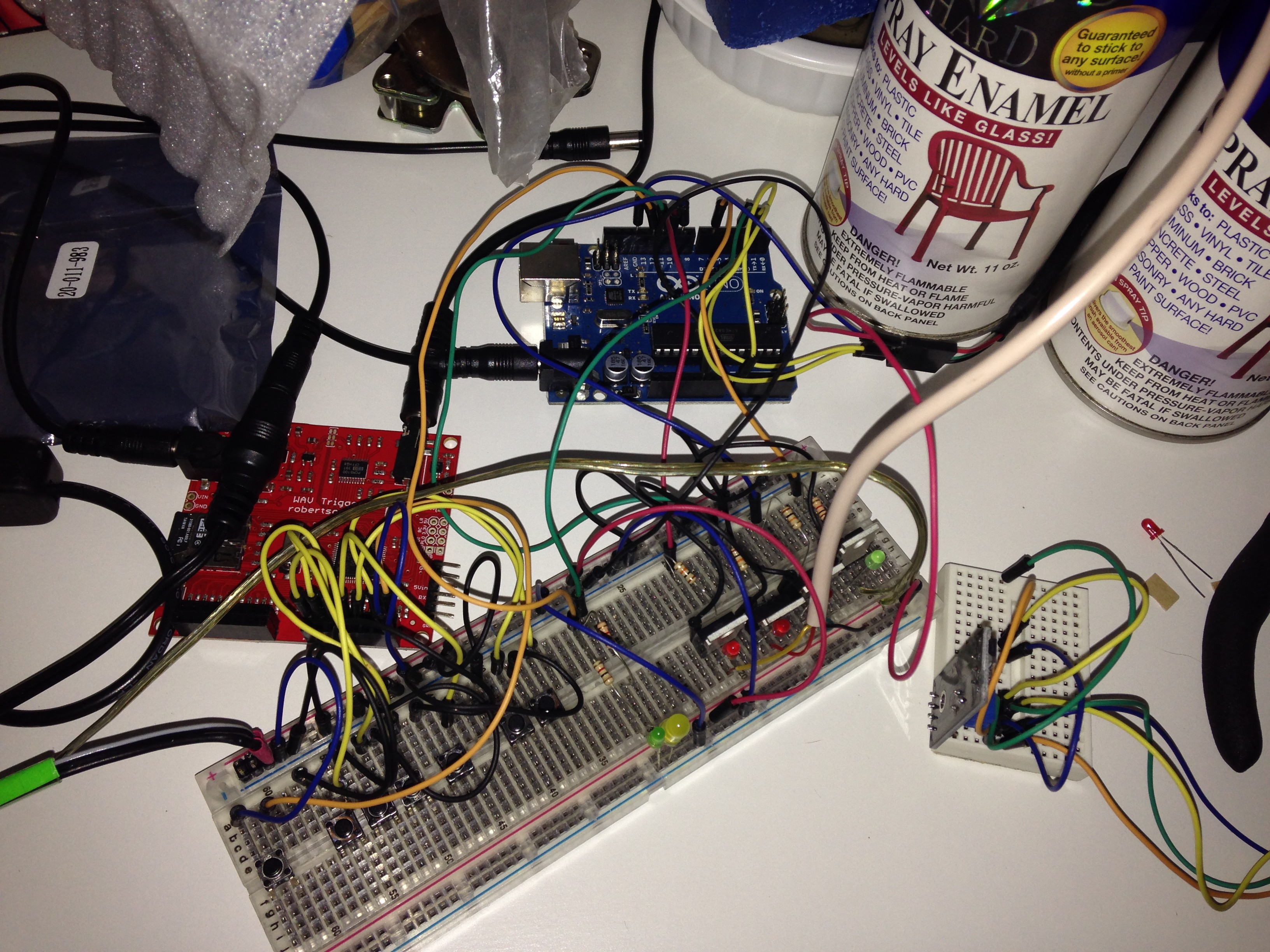
I then found this really cool WAV audio shield from SparkFun that has polyphonic sound and can be triggered either by grounding an input line or via MIDI.   

Sparkfun WAV Trigger WIG-13660

See Logs for code snippets for controlling lights and audio board.


2016 - More Lights And Door Sensors


The top door on each side has a glass window so I added more RGB LED strips at the top and under the adjustable shelf behind a strip of wood to hide the LED strips.  I connected these 4 LED strips to the existing strip for the sign.  I also wanted a separate channel for the white LED in the roof lam so that driven by another MOSFET and controlled by another PWM output.  

There are actually four doors and I wanted to add a sensor to each door.  The idea was to detect the angle of each door so I could play a creaking door sound effect which would require 4 analog input lines.  

At that point I was using 4 PWM output lines, several digital lines to trigger the various wave files and was looking at adding an IR sensor so I could use my Sonic Screwdriver TV remote to control the TARDIS which would be really cool but I was afraid of running out of I/O lines on the basic UNO. I could have switched to a Raspberry PI but that seemed like overkill and I thought I had read that there was a problem with driving PWM Chanels so I opted for an Arduino Mega which has plenty of I/O.  However I couldn't figure out a way to reliably detect the door angles and adjust the squeak in real-time so I opted for magnetic door sensors using Hall effect sensors.

Magnetic Reed Switch - Insulated 

At...

Read more »

tardis_network.h

code for using WiFi shield to trigger actions

h - 7.91 kB - 04/20/2022 at 09:19

Download

ArduinoTARDIS.ino

main program - initializes stuff and starts everything up

ino - 8.64 kB - 04/20/2022 at 09:19

Download

RGB_Pulser.h

Extends Pulser class to work on three LEDs grouped together

h - 2.31 kB - 04/20/2022 at 09:19

Download

example_network_config.h

customize network settings for your Wifi access and adafruit settings.

h - 451.00 bytes - 04/20/2022 at 09:19

Download

tardis_audio.h

Uses Robertson WAVE shield from Adafruit to play wave files.

h - 4.20 kB - 04/20/2022 at 09:19

Download

View all 9 files

View all 10 components

  • Network Code

    cafelizardo04/04/2022 at 10:21 0 comments

    The WiFi shield from Adafruit allows me to control the TARDIS from a tablet or smartphone.

    Code Snippet for triggering actions based on messages received via AdaFruit cloud

    /*
     * tardis_network.h
     * Claude Felizardo 2018-10-06
     * 
     * uses wifi board form Adafruit
     */
    
    #ifndef _tardis_network_h_
    #define _tardis_network_h_
    
    #define TARDIS_NETWORK_VERSION "$Id$"
    
    #include <SPI.h>
    #include "Adafruit_MQTT.h"
    #include "Adafruit_MQTT_Client.h"
    #include <WiFi101.h>
    #include "network_config.h"     // wifi and adafruit io config info
    
    int network_status = WL_NO_SHIELD;
    
    //Set up the wifi client
    WiFiClient client;
    
    Adafruit_MQTT_Client mqtt(&client, AIO_SERVER, AIO_SERVERPORT, AIO_USERNAME, AIO_KEY);
    
    // Setup various feeds to control the tardis
    Adafruit_MQTT_Subscribe mqtt_power_off = Adafruit_MQTT_Subscribe(&mqtt, AIO_USERNAME "/feeds/tardis.power-off");
    Adafruit_MQTT_Subscribe mqtt_door_switch = Adafruit_MQTT_Subscribe(&mqtt, AIO_USERNAME "/feeds/tardis.door-switch");
    Adafruit_MQTT_Subscribe mqtt_stop_sound = Adafruit_MQTT_Subscribe(&mqtt, AIO_USERNAME "/feeds/tardis.stop-sound");
    Adafruit_MQTT_Subscribe mqtt_play_sfx = Adafruit_MQTT_Subscribe(&mqtt, AIO_USERNAME "/feeds/tardis.play-sfx");
    Adafruit_MQTT_Subscribe mqtt_play_theme = Adafruit_MQTT_Subscribe(&mqtt, AIO_USERNAME "/feeds/tardis.play-theme");
    Adafruit_MQTT_Subscribe mqtt_lights_off = Adafruit_MQTT_Subscribe(&mqtt, AIO_USERNAME "/feeds/tardis.lights-off");
    Adafruit_MQTT_Subscribe mqtt_roof_light = Adafruit_MQTT_Subscribe(&mqtt, AIO_USERNAME "/feeds/tardis.roof-light");
    Adafruit_MQTT_Subscribe mqtt_sign_color = Adafruit_MQTT_Subscribe(&mqtt, AIO_USERNAME "/feeds/tardis.sign-color");
    Adafruit_MQTT_Subscribe mqtt_sound_bank = Adafruit_MQTT_Subscribe(&mqtt, AIO_USERNAME "/feeds/tardis.sound-bank");
    
    void tardis_network_setup() 
    {
        Serial.println("Setting up WiFi...");
        WiFi.setPins(WINC_CS, WINC_IRQ, WINC_RST, WINC_EN);
    
        // Initialise the Client
        Serial.print(F("\nInit the WiFi module..."));
        // check for the presence of the breakout
        if ((network_status = WiFi.status()) == WL_NO_SHIELD) {
            Serial.println("WINC1500 not present");
            // don't continue:
            // while (true);
        } else {
            Serial.println("ATWINC OK!");
        }
    
        mqtt.subscribe(&mqtt_power_off);
        mqtt.subscribe(&mqtt_stop_sound);
        mqtt.subscribe(&mqtt_play_sfx);
        mqtt.subscribe(&mqtt_play_theme);
        mqtt.subscribe(&mqtt_lights_off);
        mqtt.subscribe(&mqtt_roof_light);
        mqtt.subscribe(&mqtt_sign_color);
        mqtt.subscribe(&mqtt_door_switch);
        mqtt.subscribe(&mqtt_sound_bank);
    
        Serial.println("WiFi setup done.");
    } // tardis_network_setup
    
    // Function to connect and reconnect as necessary to the MQTT server.
    // Should be called in the loop function and it will take care of connecting.
    void MQTT_connect() {
    
        // attempt to connect to Wifi network:
        while ((network_status = WiFi.status()) != WL_CONNECTED) {
            Serial.print("Attempting to connect to SSID: ");
            Serial.println(WIFI_SSID);
            network_status = WiFi.begin(WIFI_SSID, WIFI_PASS);
    Serial.print("network_status="); Serial.println(network_status);
    
            // wait 10 seconds for connection:
            uint8_t timeout = 10;
            while (timeout && ((network_status = WiFi.status()) != WL_CONNECTED)) {
                timeout--;
                delay(1000);
            }
        }
        //if (WiFi.status() == WL_CONNECTED) {
        //  Serial.print("Connected to SSID");
        //}
    
        // return if already connected.
        if (mqtt.connected()) {
            return;
        }
    
        Serial.print("Connecting to MQTT... ");
    
        int8_t ret;
        while ((ret = mqtt.connect()) != 0) { // connect will return 0 for connected
            Serial.println(mqtt.connectErrorString(ret));
            Serial.println("Retrying MQTT connection in 5 seconds...");
            mqtt.disconnect();
            delay(5000);  // wait 5 seconds
        }
        Serial.println("MQTT Connected!");
    } // MQTT_connect()
    
    void tardis_network_check()
    {
        // Ensure the connection to the MQTT server is alive (this will make the first
        // connection and automatically reconnect when disconnected).  See the MQTT_connect
        // function definition further below.
        if (network_status != WL_NO_SHIELD)
     MQTT_connect();
    ...
    Read more »

  • ATX power shield code

    cafelizardo04/04/2022 at 09:31 0 comments

    I use the SparkFun ATX Power Shield to control the 6 PWM LED channels.

    SparkFun Power Driver Shield Kit

    Code snippet for controlling the ATX shield

    /*
     ATX shield with ATX control
     claude felizardo 2018-08-06
     
     https://www.sparkfun.com/products/10618
    
     Uses modified ATX shield to use pin 2 to control PS_ON control pin on ATX connector.
     */
    
    #ifndef _atx_shield_h_
    #define _atx_shield_h_
    
    #define ATX_SHIELD_VERSION "$Id$"
    
    class ATX_Shield
    {
        int atx_ctl_pin = 0;    // output for controlling ATX power supply
        int atx_enabled = 0;    // current state
    
        public:
        ATX_Shield(int output_pin)
        {
            atx_ctl_pin = output_pin;
        }
    
        void output_power()
        {
            Serial.print("atx_enabled = "); Serial.println(atx_enabled, DEC);
            digitalWrite(atx_ctl_pin, atx_enabled == 0 ? HIGH : LOW);
        } // output_power
    
        // this should be called once
        void setup()
        {
            pinMode(atx_ctl_pin, OUTPUT);
    
            atx_enabled = 0;
            output_power();
        }
    
        int isEnabled()
        {
            return atx_enabled;
        }
    
        void powerOn()
        {
            if (!atx_enabled) {
                atx_enabled = 1;
                output_power();
            }
        }
    
        void powerOff()
        {
            if (atx_enabled) {
                atx_enabled = 0;
                output_power();
            }
        }
    
    }; // class ATX_Shield
    
    #endif // _atx_shield_h_

  • Door Detection

    cafelizardo04/04/2022 at 09:22 0 comments

    The original plan was to use analog inputs to somehow measure the angle of the doors and adjust the audio sound effects on the fly as well as trigger the lights.  Couldn't figure it out so I settled for using Hall effect sensors in the cabinet that are triggered by magnets in the doors.


    Code snippet for detecting if any of the 4 doors are open or closed.

    const int DOOR_1 = 40;
    const int DOOR_2 = 41;
    const int DOOR_3 = 42;
    const int DOOR_4 = 43;
    
    // live or prototype
    int invert = -1;
    
      // initialize inputs
      pinMode(DOOR_SWITCH, INPUT_PULLUP);
      pinMode(DOOR_1, INPUT_PULLUP);
      pinMode(DOOR_2, INPUT_PULLUP);
      pinMode(DOOR_3, INPUT_PULLUP);
      pinMode(DOOR_4, INPUT_PULLUP);
    
    
    int getDoorPosition() {
        return 0
            +  1 * (digitalRead(DOOR_1) ^ (1 - invert))
            +  2 * (digitalRead(DOOR_2) ^ (1 - invert))
            +  4 * (digitalRead(DOOR_3) ^ (1 - invert))
            +  8 * (digitalRead(DOOR_4) ^ (1 - invert))
          //+ 16 * (digitalRead(DOOR_SWITCH) ^ (1 - invert))
            ;
    }

  • Sound effects

    cafelizardo04/04/2022 at 08:52 0 comments

    I really like the Robertson WAVE shield from Adafruit that can play multiple channels at the same time. Initially I used individual digital output pins from the Arduino to pull the level inputs on the WAV board but I eventually switched to using the MIDI interface. I wanted to preserver the ability to upload new code into the Arduino using the default serial port so I needed another serial port which is when I upgraded to an Arduino Mega board.   The code assumes particular tracks are stored on the SD card on the shield.


    Code snippet for controlling audio playback

    /*
     * tardis_audio.h
     * Claude Felizardo 2018-08-29
     * 
     * uses Wave Trigger library for Robertson WavTrigger board from Adafruit
     */
    
    #ifndef _tardis_audio_h_
    #define _tardis_audio_h_
    
    #if 1
    // Wave trigger library using software UART
    // https://github.com/robertsonics/WAV-Trigger-Arduino-Serial-Library
    #include <Metro.h>            // Timer class used by AltSoftSerial
    #include <AltSoftSerial.h>    // Software serial on Uno uses 16-bit timer, Rx8, Tx9, PWM10 not available
    // https://www.pjrc.com/teensy/td_libs_AltSoftSerial.html
    #define __WT_USE_ALTSOFTSERIAL__
    #else
    #define __WT_USE_SERIAL3__
    #endif
    #include <wavTrigger.h>     // wave trigger library
    
    #define TARDIS_AUDIO_VERSION "$Id$"
    
    
    class List {
        int* array;
        int count;
        int index;
        enum {ORDERED, SHUFFLED, RANDOM} order;
      public:
        List(int list[], int count)
        {
          this->array = (int*)calloc(count, sizeof(int));
          this->count = count;
          this->index = 0;
          this->order = ORDERED;
          for (int idx = 0; idx < this->count; idx++) this->array[idx] = list[idx];
        }
        int size() {
          return this->count;
        }
        int getNext() {
          if (this->index >= this->count) {
            switch (this->order) {
              case SHUFFLED:
              case RANDOM: shuffle();
                break;
            } // switch
            this->index = 0;
          }
          return this->array[this->index++];
        }
        void shuffle() {
          for (int idx = 0; idx < this->count; idx++) {
            int r = random(idx, this->count);
            int temp = this->array[idx];
            this->array[idx] = this->array[r];
            this->array[r] = temp;
          }
          this->order = SHUFFLED;
        }
        void print(const char* name) {
            char buffer[200];
            sprintf(buffer, "%s num tracks is %d", name, size());
            Serial.println(buffer);
            for (int i = 0; i < size(); i++) {
                int z = getNext();
                sprintf(buffer, "%d: track=%d", i, z);
                Serial.println(buffer);
            }
        }
    }; // class List
    
    int TARDIS_tracks[] = {1009, 1010, 1011, 1012};
    List TARDIS_list(TARDIS_tracks, sizeof(TARDIS_tracks) / sizeof(int));
    int Theme_tracks[] = {2009, 2010, 2011, 2012};
    List Theme_list(Theme_tracks, sizeof(Theme_tracks) / sizeof(int));
    int Num_tracks[] = { 1, 2, 3, 4, 5, 6, 7, 8, 9, 10, 11, 12, 13, 14, 15, 16, 17, 18};
    List Num_list(Num_tracks, 9);//sizeof(Num_tracks) / sizeof(int));
    int Alt_tracks[] = {500, 501, 502, 503, 504, 505};
    List Alt_list(Alt_tracks, sizeof(Alt_tracks) / sizeof(int));
    
    class TardisAudio
    {
    static wavTrigger wTrig;    // Our WAV Trigger object
    
    public:
    
        static void setup()
        {
            Serial.println("TardisAudio::setup(): calling wTrig.start()");
            // WAV Trigger startup at 57600
            wTrig.start();
    
            // If the Uno is powering the WAV Trigger, we should wait for the WAV Trigger
            //  to finish reset before trying to send commands.
            Serial.println("TardisAudio::setup(): waiting for WAV trigger to start");
            delay(1000);
    
            // If we're not powering the WAV Trigger, send a stop-all command in case it
            //  was already playing tracks. If we are powering the WAV Trigger, it doesn't
            //  hurt to do this.
            Serial.println(F("TardisAudio::setup(): calling stopAllTracks"));
            wTrig.stopAllTracks();
    
            TARDIS_list.shuffle();
            TARDIS_list.print("TARDIS");
    
            Theme_list.shuffle();
            Theme_list.print("Theme");
    
            Num_list.shuffle();
            Num_list.print("Num");
    
            Alt_list.shuffle();
            Alt_list.print("Alt");
    
            TardisAudio::stopAll();
    
            Serial.println("TardisAudio::setup(): returning");
        } // setup
    
        static void stopAll()
        {
            Serial.println("Stopping audio");
            wTrig.stopAllTracks();
        } // stopAll
    
        static void playTrack(int track)
        {
            wTrig.trackPlaySolo(track);
        } // playTrack
    
        static...
    Read more »

  • Code For Pulsing Lights

    cafelizardo04/04/2022 at 08:20 0 comments

    I defined a set of classes for controlling the LED lights.  The base class is called Flasher which will cycle an LED on and off at a specified rate.  The Pulser class will slowly brighten and dim an LED using a PWM output pin.  Finally the RGB_Pulser class will work on a set of three PWM pins.

    I use these classes to control the various lights as follows:

    // Flasher ctor takes led, on perid and off period
    Flasher builtin_led(LED_BUILTIN, 10, 1000); // flash power light at a steady interval
    
    // Pulser ctor takes pin, interval, maxValue, initial, increment, offset
    Pulser roof_light(ROOF_LIGHT, 5, 63, 20, 10, 0);
    //Flasher roof_light(ROOF_LIGHT, 100, 50);
    
    //Pulser cabinet_light(CABINET_LIGHT, 5, 63, 20, 10, 0);
    Flasher cabinet_light(CABINET_LIGHT);
    
    // RGB_Pulser ctor takes pins for red green and blue
    RGB_Pulser sign_color(SIGN_RED_LED, SIGN_GREEN_LED, SIGN_BLUE_LED);
    
    // Flasher -- based on tutorial from Adafruit
    // https://learn.adafruit.com/multi-tasking-the-arduino-part-1
    
    
    #ifndef _Flasher_h_
    #define _Flasher_h_
    
    #define FLASHER_VERSION "$Id: Flasher.h 2 2018-08-29 07:08:22Z cafelizardo $"
    
    enum { DISABLED = -1, OFF=LOW, ON=HIGH } LED_STATE;
    
    class Flasher
    {
        protected:
        // configuration variables
        int ledPin;                      // number of the LED pin
        long onTime;                     // milliseconds of on-time
        long offTime;                    // milliseconds of off-time
        bool inverted;                   // invert output
    
        // state variables
        int ledState;                    // current value: DISABLED, OFF or ON
        unsigned long previousMillis;    // last time LED was last updated
    
        public:
        // constructor -- creates a Flasher object
        // and initialized the member variables and state
        Flasher(int pin = 0, long on = 0, long off = 0)
        {
            this->ledPin = pin;
            pinMode(ledPin, OUTPUT);
    
            this->onTime = on;
            this->offTime = off;
            this->inverted = false;
            this->ledState = OFF;
            this->previousMillis = 0;
        } // ctor
    
        // modifiers
        Flasher& setOnTime(long onTime) {
            this->onTime = onTime;
            return *this;
        }
        Flasher& setOffTime(long offTime) {
            this->offTime = offTime;
            return *this;
        }
        Flasher& setInvert(bool invert) {
            this->inverted = invert;
            return *this;
        }
        virtual Flasher& output(int value)
        {
            if (this->ledState == DISABLED) {
                digitalWrite(this->ledPin, this->inverted ? HIGH : LOW);
            } else {
                digitalWrite(this->ledPin, constrain(this->inverted ? 255 - value : value, 0, 255) );
            }
            return *this;
        }
        virtual Flasher& output()
        {
            //Serial.print("Flasher.output "); Serial.print(this->ledPin, DEC); Serial.println("");
            this->output(this->ledState);
            return *this;
        }
        virtual Flasher& disable() {
            //Serial.print("disabling "); Serial.print(this->ledPin, DEC); Serial.println("");
            this->ledState = DISABLED;
            this->output();
            return *this;
        }
        virtual Flasher& enable() {
            //Serial.print("enabling "); Serial.print(this->ledPin, DEC); Serial.println("");
            this->ledState = OFF;
            this->previousMillis = 0;
            this->output();
            return *this;
        }
    
        virtual Flasher& update()
        {
            if (this->ledState == DISABLED) return *this;
    
            //Serial.print("flasher update "); Serial.print(this->ledPin, DEC); Serial.println("");
            // check to see if it's tme to change the state of the LED
            unsigned long currentMillis = millis();
    
            bool toggle = false;
            if ( (this->ledState == ON) && (currentMillis - this->previousMillis >= this->onTime) )
                toggle = true;
            else if ( (this->ledState == OFF) && (currentMillis - this->previousMillis >= this->offTime) )
                toggle = true;
    
            if (toggle)
            {
                this->ledState = !this->ledState;
                this->output();
                this->previousMillis = currentMillis;
            }
            return *this;
        } // update
    
    }; // class Flasher
    
    #endif // _flasher_h_
    
     
    // Pulser -- extends Flasher by gradually increasing brightness then back down again
    // initial version using cosine function.
    
    #ifndef _Pulser_h_
    #define _Pulser_h_
    
    #include "Flasher.h"
    
    #define PULSER_VERSION "$Id: Pulser.h 9 2018-10-01 07:19:06Z cafelizardo $"
    
    class Pulser : public Flasher
    {
        long interval;
        long offset;        // offset to be applied after computing value to force clipping either low...
    Read more »

View all 5 project logs

Enjoy this project?

Share

Discussions

Similar Projects

Does this project spark your interest?

Become a member to follow this project and never miss any updates