 Guillermo Perez Guillen
In this test, we are going to use a different program. You can find the program in the Code section. Project repository: "PID Battery Charger With Night Light Control"
How does it work?
a) If we want to take control of a system, the best solution is to make use of the PID control. PID is a control loop feedback mechanism widely used in industrial control systems and a variety of other applications requiring continuously modulated control. A PID controller continuously calculates an error value as the difference between a desired setpoint (SP) and a measured process variable (PV) and applies a correction based on proportional, integral, and derivative terms (denoted P, I, and D respectively), hence the name.
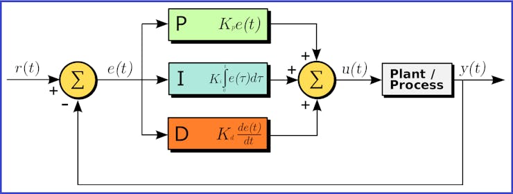
PID controller
In my case, STM32F507 board generates a PWM signal of 30 kHz, and the control data are: dt = 0.0005, Kp = 0.025 and Ki =0.025. You may notice that the derivative term is very small or null., and the simulation of my PID controller is the following:
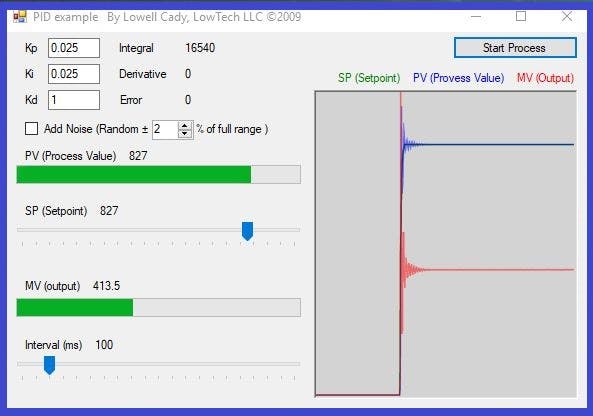
Using the Lowell Cady program, to test my PID controller.
https://en.wikipedia.org/wiki/PID_controller
b) The work of deciding when to apply a PWM control signal is left to the STM32F407 board. In my example, this board does the calculations and generating the PWM control signal. With my PICkit2 device, I got the following PWM signals.
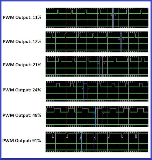
The PID controller generates many duty cycles, and these depend on the feedback.
c) The voltage divider VR5 delivers an analog value to our port PA1, and this is compared to the "setpoint". The "setpoint" is programmed by code and we did one setpoint test: VBattery = 4.95 volts / VR5 = 2, 2 volts / ADC = 3003 ADC.
  declare
     Value     : Percentage;
     Raw1      : Long_Float;
     setpoint  : constant := 3003.0; -- VR5 = 2.2 volts / Vbat = 4.95 volts
     error     : Long_Float := 0.0;
     output    : Long_Float;
     integral  : Long_Float := 0.0;
     dt        : constant := 0.0005;
     Kp        : constant := 0.025;
     Ki        : constant := 0.025;
d) For example, If the battery is discharged, then the program calculates the error, and generates a PWM signal with a high duty cycle. If the battery is charged, then the program generates a PWM signal with a small duty cycle.
 begin
        STM32.User_Button.Initialize; -- btn instruction
     loop
        Start_Conversion (Converter); --adc instruction
        Poll_For_Status (Converter, Regular_Channel_Conversion_Complete, Successful); --adc instruction
        Raw := UInt32 (Conversion_Value (Converter)); -- reading PA1
        Raw1 := Long_Float(Raw * 1);
        error := (setpoint - Raw1);
        integral := (integral + (error*dt));
        output := ((Kp*error) + (Ki*integral));
        Value := Percentage (output); -- duty cycle value
        if Value < 10 then -- if the duty cycle < 10%
           Power_Control.Set_Duty_Cycle (10);
           Red_LED.Set; -- Red LED os ON
           Green_LED.Clear; -- Green LED is OFF
           Orange_LED.Clear; -- Orange LED is OFF
           delay until Clock + Milliseconds (500); -- slow it down to ease reading
        elsif Value >= 90 then -- If the duty cycle > 90%
           Power_Control.Set_Duty_Cycle (90);
           Red_LED.Clear; -- Red LED is OFF
           Orange_LED.Set; -- Orange LED is OFF
        elsif STM32.User_Button.Has_Been_Pressed then -- If PA0 is ON
           Green_LED.Set; -- Green LED is ON
        else -- If the duty cycle is from: 10 - 90 %
           Power_Control.Set_Duty_Cycle (Value); -- PWM signal
           Orange_LED.Set; -- Orange LED is ON
           Red_LED.Set; -- Red LED is ON
        end if;
        delay until Clock + Milliseconds (10); -- slow it down to ease reading
     end loop;
Now we have an intelligent system that has the advantage of generating many duty cycles, and we will make a more efficient use of energy.
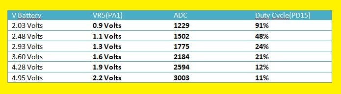
These are examples of the values obtained with the PID controller
Discussions
Become a Hackaday.io Member
Create an account to leave a comment. Already have an account? Log In.