 kelvinA
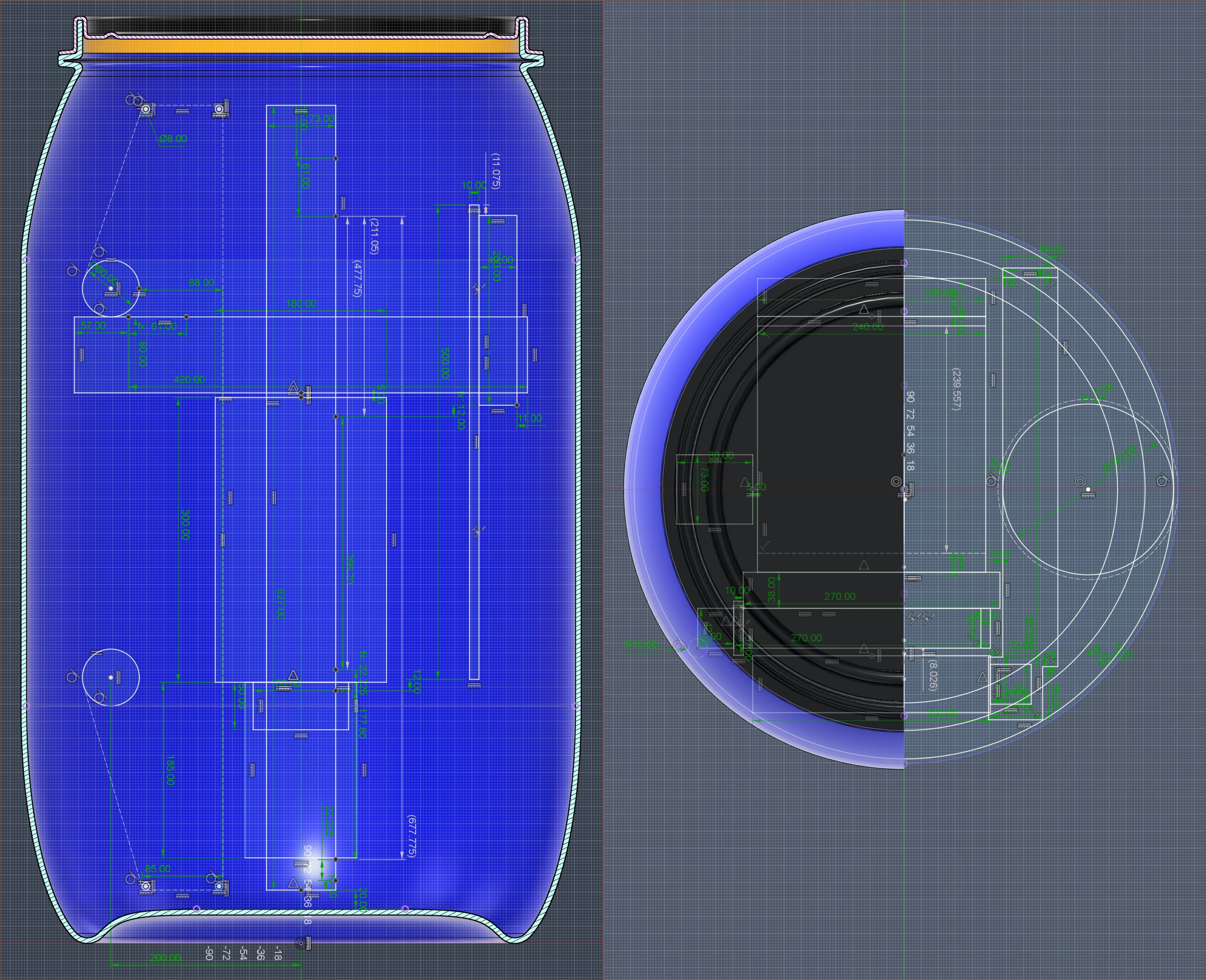
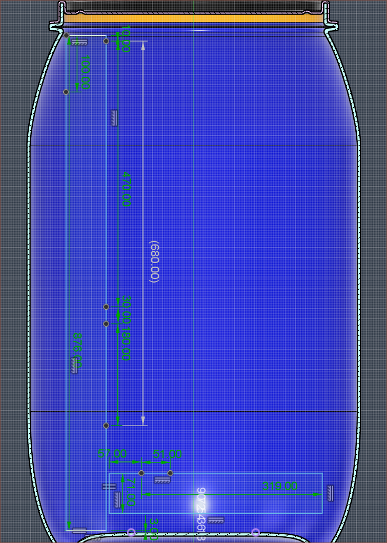
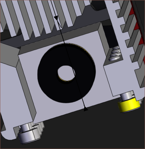
I've unintentionally put in upwards of 9-hour days for... checks notes... 7 days to get the above solution which achieves multiple desired goals. As you might understand, the first complication is that I need to work within a cylindrical area. The second is that it's not a pure cylinder but curves at the top/bottom similar to a filleted chamfer, meaning some things only fit at certain heights. If you look at the top-down angle above, that's the reason why there are 3 concentric circles to denote the perimeter of the barrel at its widest section, about an inch from the opening and the opening itself.
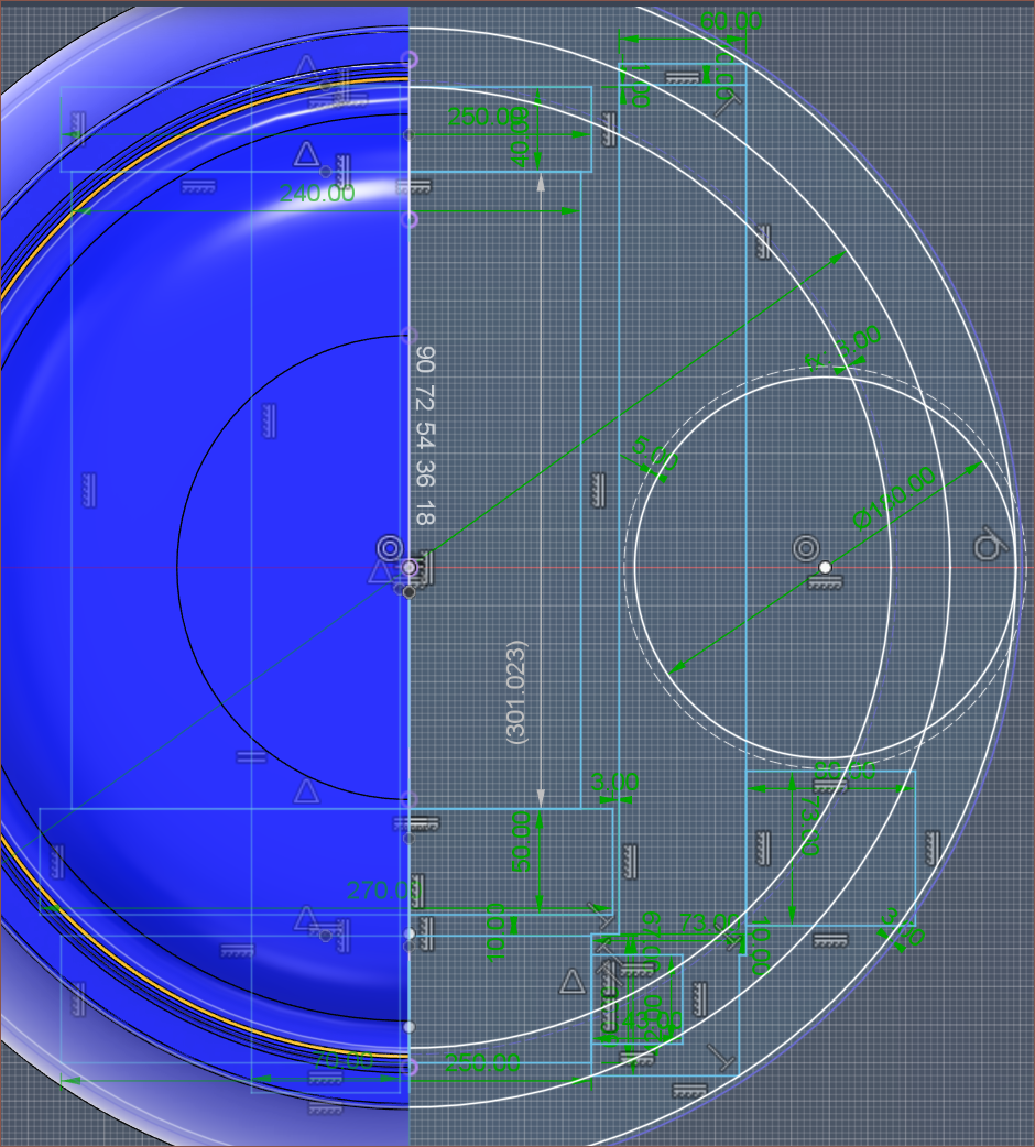
Printers I've seen, like the Ender 3, have the screen on the right side. Thus, that's why the print volume is more leftwards. I plan to have the screen on the inside and perhaps a status LED on the outside.
Most of the time was on the motion system. Considering that, unlike FFF, this application calls for very precise movements that don't need to be particularly fast, it's probably no surprise that most of my research was on ball screws. Considering my work on delta belt tensioners, I've decided that I'd rather not deal with belts and the design/manufacturing time that comes with it.
Day 1
One of the first things I saw was the below video:
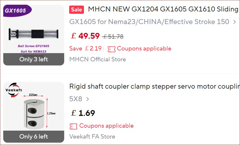
Then I went on AliExpress to see different options and how much extra length is needed for an axis. The lowest I found was 119 - 120mm.
Day 2
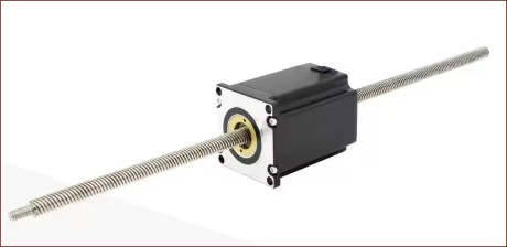
I found out about non-captive stepper motors:
I was also asking Gemini about some questions about the build plate material. Both it and I believe that a typical aluminium bed will interfere with the charged-plate responsible for attracting uncured resin back onto the film.
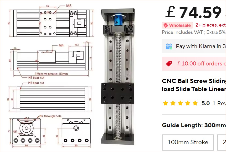
Then I found out about enclosed sliding tables, which look as sleek as the Windstorm S1 I mentioned a few logs back:
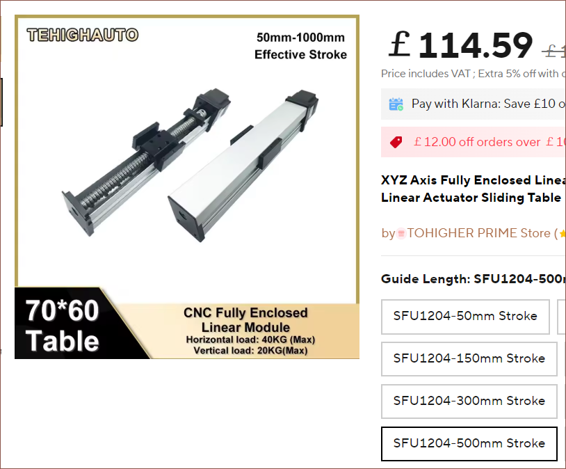 I thought this would be particularly useful for the Z axis. If kept in the orientation seen above, the build plate would be vertical and exhibit no counter-lever sagging, unlike the typical orientation for 3D printers having the build plate parallel with the ground. This was one of many reasons for keeping the barrel upright. However, this orientation risks resin falling onto the ballscrew. Hence, that's why I thought this enclosed module would be beneficial.
Then I found a forum post titled Ballscrew Basics where the OP mentioned some interesting things. notably:
"But what about accuracy?? Isn't that the primary reason to use a ballscrew?" True, accuracy can be extremely high, but ACME screws can be ground and with a correct, matching nut, can exhibit identical accuracy to the finest ballscrew.
This claim both tracks with the video above and the Prometheus MSLA designers testing both a lead and ball screw. One of the bigger factors is efficiency:
A typical ACME threadform has an efficiency of roughly 40%, whereas a ballscrew's efficiency can easily top 90%.
Hypothetically, wear is another one I've read in multiple different locations over the years, but in all my 8 years of scanning the entire internet for 3D printing information have I seen something along the lines of "my T8 lead nut wore down and I needed to replace it".
A specifically important part are the bearings though:
A C0 ballscrew is worthless if it is supported by a single, standard radial ball bearing.
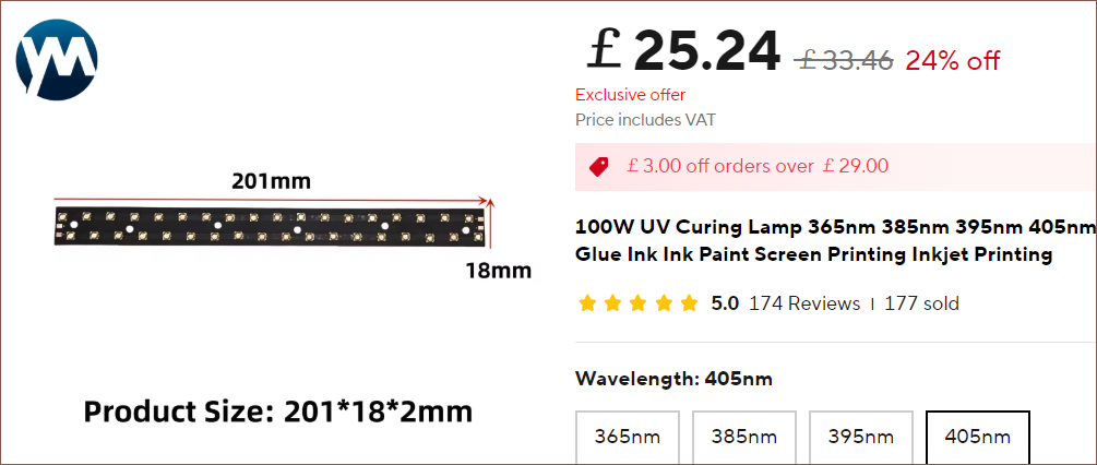
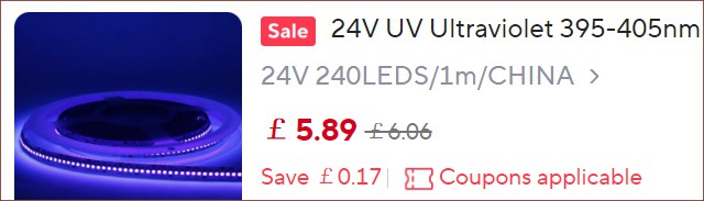
Moving on, I found this 201mm curing lamp but I'm likely just going to use a 240LED/m 405nm strip:
Up until this point, I hadn't even really started to think about the cartridge situation. I had the great idea of
- having each cartridge be 44.45mm tall (the same as 1U in a server cabinet)
- a cam system such that the Y axis could select what cartridge is pressed onto the film-covered LCD,
- designing a dynamic system such that trades Y print space for cartridges.
- The X length of the LCD is a tad shorter than 3 cartridges, so the adjustment would essentially be a range of 2 - 4 LCD-lengths.
- Thus, I could design so that the standard set of 4 cartridges allows for the full 470mm build depth, additional CMY allows for around 330mm and, if needed, another set of RGB cartridges for around 200mm.
To facilitate this, A way to easily swap between print beds of multiple lengths would be required.
Day 3
This was the day I found out how to get around the current AliExpress bug that it doesn't allow me to put stuff in the basket because of some "new user" discount when I'm signed in. I can add it into the basket via the wishlist.
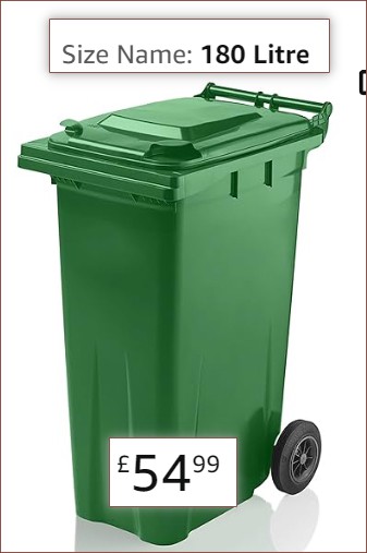
I was feeling the squish of the barrel and was wondering the potential to use a wheelie bin because they're large and rectangular and about a meter tall, which is needed for the Y axis:
I finished this day having issues with fitting the 700mm axis as well as having space for the PET film:
Day 4
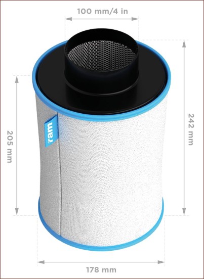
Considered going down to 600mm and aiming for 5 materials and 350mm Y, somewhat competing with the Prusa XL. Then I found out that the 4" part of 4" filters were only the opening and that the actual diameters of them are typically a tad less than 180mm:
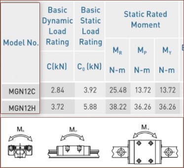
This was also when I considered using these 80mm wide, 2*MGN12C sliders for the Y:
Later in the day, I found out that they also come in a 4*MGN12H configuration:
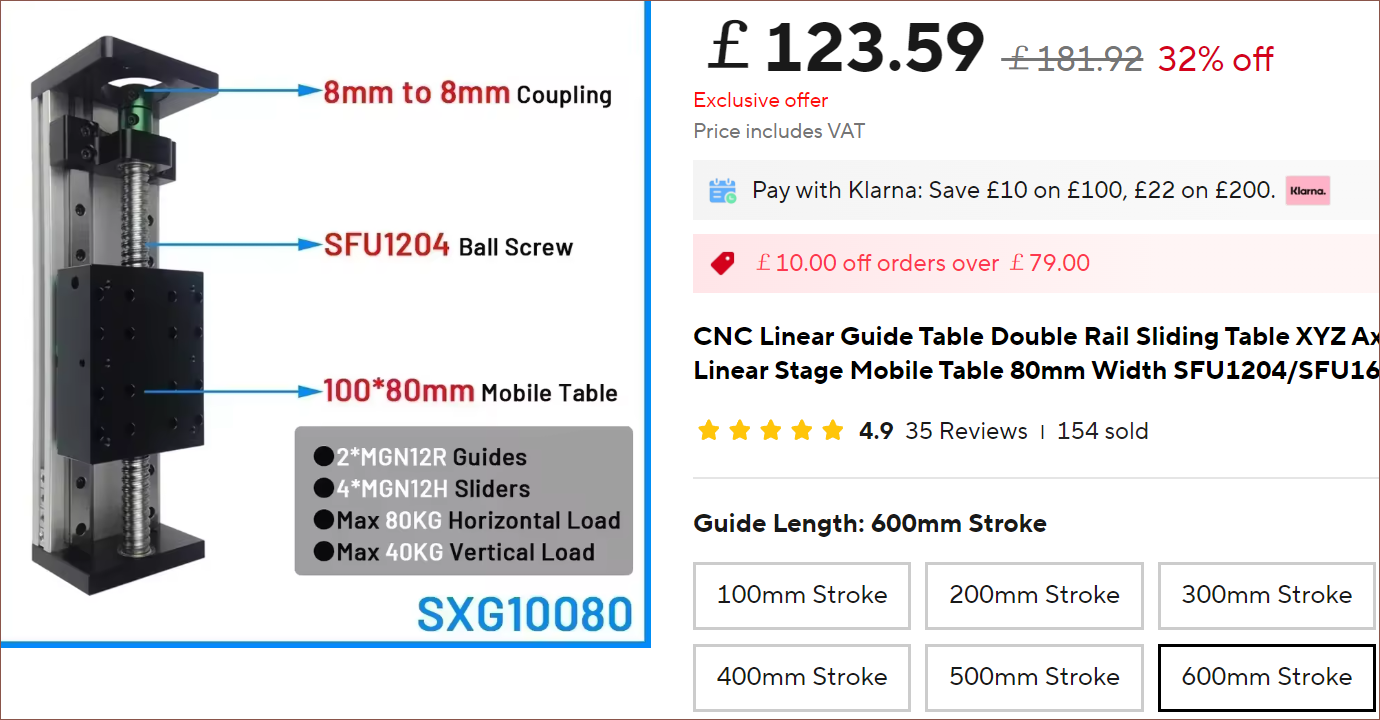
What I realised is that, in the sketch, I'm seeing the end-to-end stroke length, which didn't exceed 700mm. This is the effective stroke + the table length. For The 50*80 table, this means a 700mm axis is 750mm end-to-end. The printer only needs a minimum of 500mm or so to allow the scanner, curing LED strip and charge plate to sweep across the entire 470mm area. Thus, a 600mm axis with a 100*80 table could be used, saving the 50mm I needed to better fit the axis inside the barrel. The price didn't change that much from a 700mm 50*80 table.
I totalled up the length of the end effector and I got a whopping 271mm, with 102mm being the laser module and its linear axis. Yes, I'm going all the way with trying for these 3DPCBs. Probably 30% of this project has been "Will L^3 work?" and the other 70% has been "Will L^3 allow for multilayer PCBs and silkscreen?". I'm sure I've had this discussion in #SecSavr Soapalai [gd0146]; I try and remove "print PCBs" from the specifications list and it keeps coming back.
Day 5
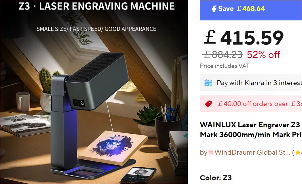
This day started by, once again, looking over laser module options (and so I did some updates to the laser module log). One cool one I found was a WAINLUX Z3, which has a 50um square spot with 4.5W of optical power and a workspace of 50*50mm for a little over £400:
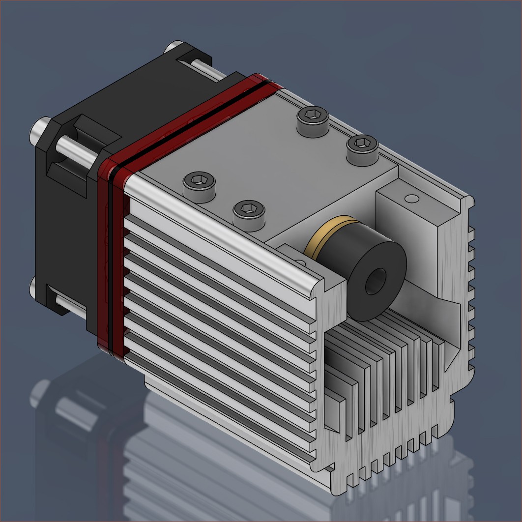
Another thing I did was look at a 3D model of the laser I found on GrabCAD:
 Along with the 0.04mm square spot and low cost, it seems ideal to use this because it seems that the included heatsink can be removed and a custom one designed if required.
Because of the large, activated carbon filter, I wondered if there would be enough space for the 50*80 slider, which wouldn't block getting things in/out of the barrel nor be in a position that risks resin getting on the components. Turns out a 300mm axis fits:
With this, the solution for fitting everything in this 220L barrel actually started to pass.
I looked around and it seems that the shortest possible filter is 200mm for its main area, or 250mm from edge to edge. Ac Infinity has the only refillable one I can find, and theirs is 260mm x 180mm with a 40mm opening:
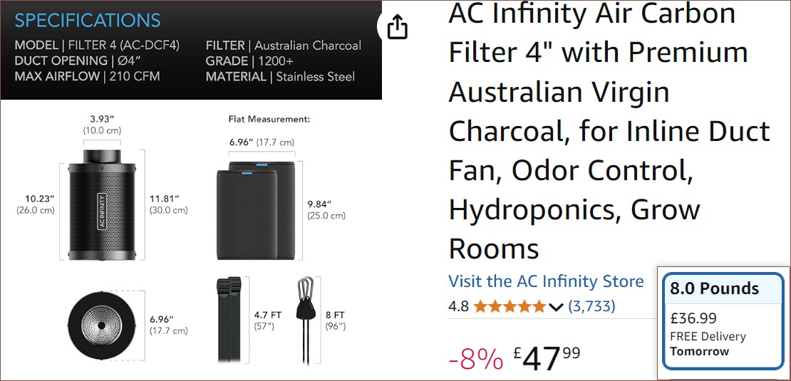
This uses 4lb of charcoal per refill. The lowest value is an 8lb bag, thus £18.50 at most for a refill. Most basic filters start at £30, but you'd get a brand-new pre-filter and not have to manually fill up the filter. However, Vivosun is currently the cheapest filter I can find that has the same 1200+ Iodine Adsorption Value is only a few pennies cheaper than the 8lb refill bag:
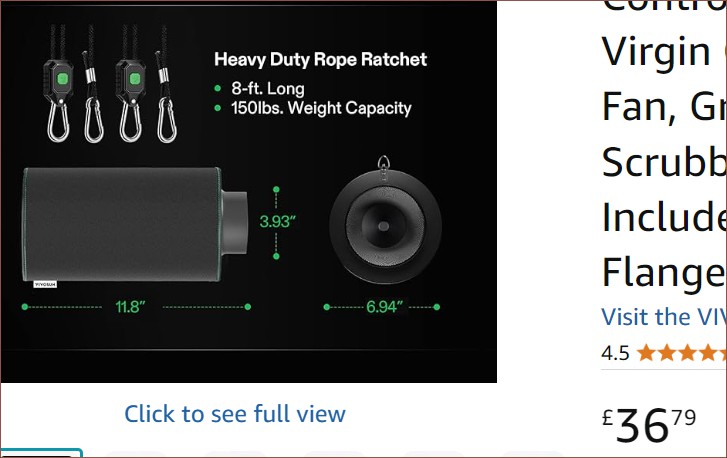
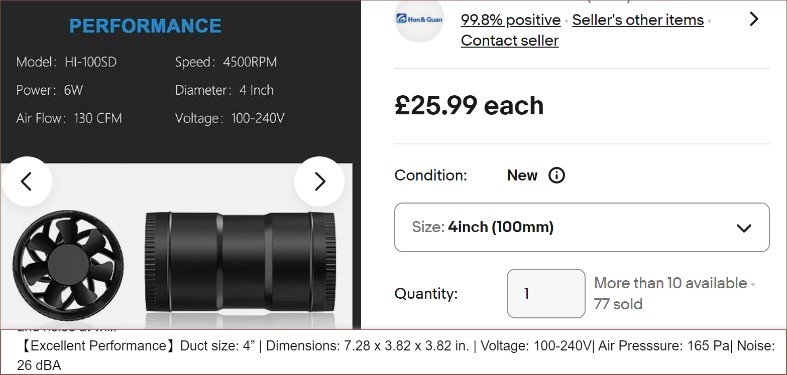
Thus, it does seem like AC Infinity's offering is cost effective, especially since they give 2 pre-filters. Someone confirmed that they don't acid-wash the carbon, which will oxidise metal surfaces in minutes. I also looked into industrial filtration, and it seems that the only difference is that they use activated carbon pellets and the fans are obviously larger than this 26dB one I found the following day:
 For context, a 220L volume is about 8 cubic feet.
Day 6
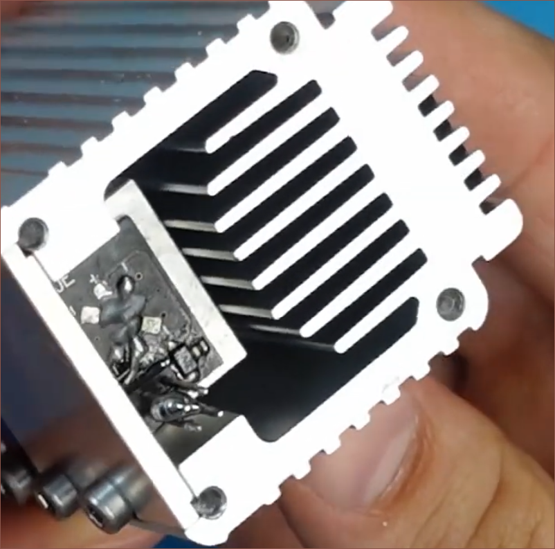
I found this repair video that is essentially a teardown of the NEJE laser module:
I determined that the best solution is to have a single MGN12C table mounted behind the 38mm screen module and mount the laser such that it shines through a 5mm gap, as the charge plate, CIS and LED strip are all relatively thin. One solution could be to trim the heatsink by 15mm:
 Realistically, the main concern is to make sure that the laser is not in focus when going through the PET film, which has the potential for a stray particulate to stick onto it, potentially vaporising and poking a hole in the film.
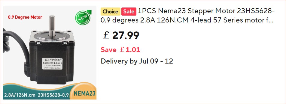
I spent quite a lot of time wondering if I should use SFU1610 and a 0.9-degree Nema17 to get the same effective resolution, but then I found out that 0.9-degree Nema 23 steppers indeed exist and so I'm sticking with SFU1605 for all axes.
150mm stroke fits, which I believe is good. The full Y axis length can be used for a PCB, unlike my earlier assumption a few weeks ago thinking that it would be 1 LCD-length short. I'm trying to compete with JLCPCB so it should be fine as long as the laser axis is at least over 100mm. With 148*470mm, an entire 100% keyboard PCB could be printed. That's a good size for mechanical keyboard hobbyists 😏.
Day 7
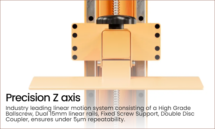
I stumbled upon the Athena II which is also using the new 16K 9.55" panel. One thing I noticed was their mention of "double disc coupler" for the Z axis:
This lead me to this rather nice looking "diaphragm coupling":
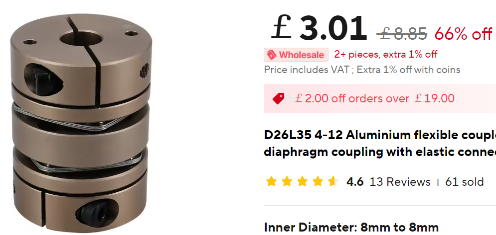
I can only assume that they're to allow axial flexibility while ensuring radial stiffness. The majority of linear tables (even the more expensive ones) seem to use a basic, rigid coupler.
I was also looking at the pros and cons of 0.9-degree steppers. It'll merely add £30 tops to the costs but its usefulness is questionable, thus I'm sticking with standard 1.8-degree for now.
For the PET, I considered taking advantage of gravity and using mass-based tension. It won't be as dynamic as dual motors, but it's an option if I'm limited by the amount of steppers. This solution already eliminates quite a lot of steppers needed compared to the very first design in 2022, such as the dual steppers for selecting the cartridge on the left/right of the machine.
Day 8 / Conclusion
So, finally, I can answer the simple yes/no on some of the questions I raised in the previous log, mainly that the solution I want can be contained in a 220L barrel. Yes, it did feel odd (and a bit disheartening) to start solving at like 0900 but the time suddenly be 1900 some days. Even at the typically-£70 cost of a barrel, I don't think someone could DIY a cheaper enclosure, especially one that's airtight and UN certified for hazardous chemicals.
I should be able to get 211*470*215mm XYZ build volume with laser diode and air filtration, assuming that the Halot-X1 module is approximately the dimensions I've estimated and I can make 1U-thick cartridges. Those cartridges might have a built-in or detachable handle, and there is the potential ability to fit 4 - 10 materials
The laser, 3 linear axes, 2 Nema23 motors and UV LED come to £300. The filter and fan is probably another £75. The screen alone is around £120, the current lowest barrel price is £55, scanner sensor and wire maybe £25, PET £10, a 5-pack of Nema17s is £35, two TMC5160s is another £25... let's just say the minimum bound is £700.
Discussions
Become a Hackaday.io Member
Create an account to leave a comment. Already have an account? Log In.