WJCarpenter
-
A change of fonts in the UI
05/06/2022 at 00:55 • 0 commentsThis is a follow-up to my project log on screen captures. In the first draft of showing the UI, I used a photo of the device taken with my cell phone. I later replaced that with screen captures, which looked much nicer. For comparison, here is the original photo of one of the images:
![]()
At that time, I was using the Mincyo fonts included in the graphics library repository. Here is that same screen as a screen capture:
![]()
That's a much better representation, but it also shows more clearly that the Mincyo fonts have a slightly sloppy look to them. I had chosen to use the Mincyo fonts because serif fonts are typically easier to read than sans serif fonts. After seeing the look in the screen captures, I switched to using the included Gothic fonts, which luckily were of the same sizes. Here is that screen with Gothic fonts:
![]()
I've decided to switch permanently to the Gothic fonts because of the tidier look. It probably matters less than I think it does when it's being viewed on that tiny screen.
-
A side-trip to screen captures
05/05/2022 at 16:27 • 0 commentsWhoa! How did I get those crisp screen captures that were part of the last project log item? Do I have some kind of super-steady professional camera rig and awesome photo editing skills? No. In fact, the first draft of that project log did use mobile phone camera shots of the board. They looked pretty terrible.
I decided to see if I could get a literal pixel-perfect screen capture of my evolving UI screens. I deduced that the ST7789 controller has some kind of internal frame buffer holding the current screen image. Looking through the datasheet, it seemed like it would be possible to read out the color values of individual pixels, though there were some configuration settings that I would have to work my way through to figure out a lot of details. (For example, the graphics package is sending 16-bit RGB 565 color codes, but the controller has different ways of storing them in its frame buffer. What would I get back?)
It seemed at least feasible to be able to read back the entire image. The next question would be how to get that data off the device so that I could use it to construct some kind of standard graphical file. I pondered all kinds of exotic possibilities. For example, I could use WiFi to publish the data over MQTT to a willing subscriber. Or I could do something -- I'm not sure what -- over Bluetooth. All of those seem like a lot of bother just to get a few screen captures. A ready-made possibility would be to send it over the USB connection. That's already wired up in an ESP-IDF application to receive log output from the various ESP_LOGx macros. But the log output really wants to be textual, not binary, and there are various bits of ESP_LOGx boilerplate that would need to be trimmed away.
I started thinking about how to encode a rectangular array of pixel values into some unambiguous text format. For example, I could send each pixel as an (x,y) point and a hexadecimal color value. I could then write some scripting that would take that as input and create a PNG file. (Note to self: research PNG file format.) If only there were a graphics file format that was already text based, that would simplify my life.
Hey, wait a minute! There is such a thing. It's Scalable Vector Graphics (SVG). In normal circumstances, SVG is a poor choice for pixel-based graphics. The whole reason for SVG is to avoid that per-pixel lock-in. But it is actually possible to do pixel things, with the standard approach being to represent them as 1x1 rectangles. Given a clunky SVG representation of a screen, there are tons of tools for converting it into a PNG, JPEG, BMP, or some other graphics formats.
So, now all I have to do is figure out how to read the pixels out of the ST7789 frame buffer (all the info I should need is in the device datasheet), encode each one as an SVG rectangle, and spit it out via ESP_LOGx statements. The scripting on the computer side to carve out the SVG should be straightforward.
Is there a simpler way? Once I started thinking about SVG, I started thinking how it was composed of logical entities: circles, lines, rectangles, etc. Come to think of it, so are the operations in the esp-idf-st7789 library that I'm using. That library is a well-organized single C source file that already has a dependency on being inside the ESP-IDF ecosystem. I decided to modify that library to optionally emit the equivalent SVG graphics via ESP_LOGx statements. (Most of my UI is text, and the graphics library renders text by placing individual pixels. SVG also has text primitives, but using them would break the goal of pixel-perfect representation.)
I sent my changes to the graphics library to the upstream author via a pull request.
The process for using this technique is straightforward. Modify the application code to make calls to start and end emitting SVG. Run that code on the device while capturing the ESP_LOGx output. Use ordinary text tools to carve the SVG part out of the overall captured logging. Go back and disable the SVG logging in the application code (it adds quite a performance burden if there are a lot of things like text painted a pixel at a time). Here is a note I left in the bleXmang code to remind myself how to do this (on Linux). It also depends on some additional logging I do between screens (you can see those details in the code).
/* To get all of the SVGs in a single HTML page, you can capture the log output like this on Linux (turn off ANSI colors in the ESP-IDF project config settings (Component confg > Log output)): idf.py monitor | grep SVG | cut -d ' ' -f 4- | tee /tmp/svg.html It won't have the end tag, but browsers don't care about that. To get the individual SVGs as separate chunks, be in an empty directory and do this: cat /tmp/svg.html | grep -v 'div>' | grep -v '' | csplit -f svg -b '%02d.svg' --suppress-matched -z - '/cut-cut-cut-cut/' '{*}' That will give you a series of files with names like "svg00.svg", "svg01.svg", etc. The graphics library is operating in portrait mode. To get landscape mode, rotate 90 CCW. With a recent version if inkscape, you can do it like this: inkscape --with-gui --verb="EditSelectAll;SelectionGroup;ObjectRotate90CCW;FitCanvasToSelection;FileSave;FileQuit" svg*.svg and then convert to PNG like this: inkscape --export-type="png" svg*.svg */ -
User interface elements
05/01/2022 at 20:01 • 0 commentsI could pretend I had a visionary design for the UI and refined my approach with extensive A/B testing and usability lab studies, but come on. This was a case of thinking about what I wanted to show while also experimenting with how to show things with a basic display library and reasonable performance. It was a case of form follows function and function follows form. What I'm describing here is pretty much the end result and mercifully skips over dead ends and boneheaded choices late withdrawn.
When I first started thinking about this project, I was imagining a rotary encoder for navigation, with selection being done by pressing the knob. Once I chose the TTGO T-Display board, I decided to see if I could make things work reasonably with just the two buttons. (The third button is to reset the device, so it's not a very good UI input.) After looking around a bit, I decided to do the interface to those two buttons with Espressif's IoT Button. It was easy to add via the ESP-IDF component manager, and it provides a simple event callback mechanism for various kinds of button presses.
I use these button events:
- Single clicks with the (physically) top and bottom buttons are used for moving the highlighted item indicator up or down, respectively. I avoided the great "Which way is natural for scrolling?" debate by never scrolling. Instead, I'm just moving an on-screen indicator around, for which I think the directional buttons are pretty obvious.
- Long press (on either button) is used to select or confirm the currently highlighted item. That always leads to some action, but sometimes the action is to navigate to a submenu.
- Double click (on either button) is used to cancel or move up one level in the menu hierarchy.
I originally decided to use long press for confirmation because the user is less prone to do that accidentally, which definitely can happen with double clicking. Contrast that with typical mouse UIs where double clicking selects the item. I'm still thinking about whether to swap my choice of what long press and double click mean. I also fiddled with the timing configuration settings for IoT Button to make mistakes less likely. It's still pretty easy to try to rapidly move the selection and end up double clicking to go up a menu level. When that happens, it's not a tragedy. Nothing is lost and the user can just long press to go back into the submenu.
I wrote an implementation for a fairly simple menu system. All menu screens have to fit on the display with no scrolling. All text is horizontal in the natural direction (at least for LTR locales) when the buttons are on the right-hand side. A menu screen is a collection of lines. Everything on a particular line is rendered in the same font (and the size is implicit in the choice of font). Lines may have an action associated with them, and that action is performed when that line is highlighted and selected. I prefixed submenu lines with ">>" and user configuration choices with "-", but that's just a convention of the text I used and is not built into the menu system. A line on the screen is a collection of line fragments. Fragments include a text color choice. They also include a text fill (background) color, though I decided to not use any after seeing how it looked (it made the text stand out, but it also made it harder to read).
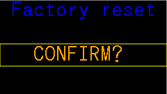
For most menus, I use a medium-sized font for a header and a small-sized font for detail lines. With that arrangement, I can comfortably fit 7 detail lines on the screen. With 5 detail lines, I can also fit a medium-sized font footer line. This arrangement is adequate for all the things I want to do (so far), though it did bleed through to functional requirements so that I changed the limit of paired Bluetooth devices to 6 in each direction (so, sue me). I only used a large-sized font in the (non-menu) Bluetooth status screen and in the "factory reset" confirmation screen. I will probably use the same scheme in some additional confirmation screens for device management. All of the menu screens were tediously hand-crafted to see that they fit on the screen and looked OK.
To highlight an item in a menu, I draw a single-pixel rectangular outline of the whole line's area regardless of how much text is actually on that line.
![]()
The fonts I'm using have at least 1 empty pixel all around the glyphs, so I can easily erase that rectangle without leaving crud on the screen. When moving the highlight around with button presses, the menu system skips over any lines that are not selectable (that is, lines without an associated action). It also wraps around the top and bottom of the screen if the user navigates past the first or last selectable item.
When the user selects an item whose action is to go to a submenu, there visual feedback is obvious: the submenu appears. When the action is something else, it's not as obvious. With the selection action being a long press, when can the user stop pressing the button? To provide visual feedback for the non-submenu cases, I blink the screen. Blinking is done by commanding the ST7789 to invert the colors for a short time and then switching back. Menus have a lot of black background, so this has the effect of being a visible white flash. Through trial and error, I selected 120 milliseconds for the duration of the blink.
The color scheme I chose for the UI is fairly simple. Overall, there is a black background. There is lots of blue and cyan text (because Bluetooth; duh!). For a typical menu, the header and footer lines are in blue with detail lines in cyan. Sometimes there is an important word or number, in which case I display it in orange (and usually uppercase if it's a word). For the highlight rectangle, I use yellow because it contrasts nicely with all the other colors.
My plan is that most of the time the device will be displaying a Bluetooth status screen.
![]()
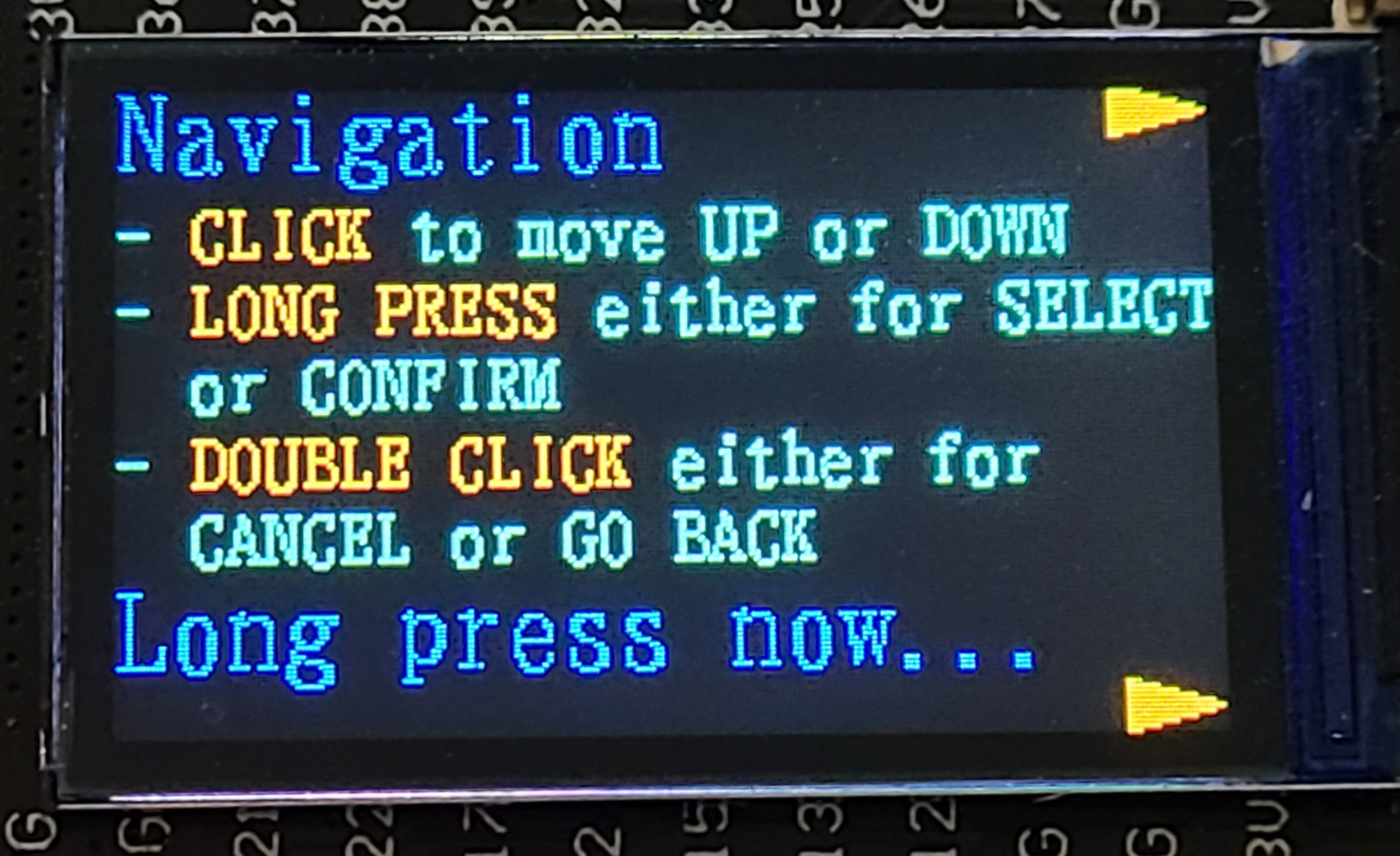
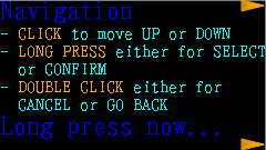
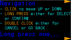
I'm hoping to have little on-screen blinky lights to indicate activity for each device (inside the small blue boxes in the photo above), but I'll have to see how that goes when I actually have some activity for some devices. While that screen is being displayed, either button press summons the menu system, with the first screen being a brief description of how the rest of the navigation works. My thinking is that even I won't remember how this works after enough time has passed.
![]()
There are two configurable timeouts:
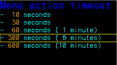
- There is an idle timeout when in the menu system. When the timeout expires, the display switches back to the Bluetooth status display. The default is 5 minutes. Expiration is determined by time since the last button press of any kind.
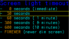
- Menus are always displayed at 100% screen brightness. The Bluetooth status display can be dimmed when a timeout expires. The default is to dim to 25% brightness after 30 seconds. The brightness percentage is also configurable. Expiration is determined simply by the amount of time since we switched to that screen.
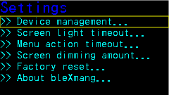
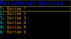
Here, without much comment, are the other UI screens not already shown above. The list of devices on the "Peripheral devices" screen is just dummied up for UI design purposes. Eventually, slots will be populated with the names of devices actually paired with the bleXmang device. There is a "Central devices" screen (not shown) that is visually similar.
![]()
![]()
![]()
![]()
![]()
![]()
![]()
-
User interface and display library
05/01/2022 at 18:36 • 1 commentAs a world-class procrastinator, I have so far spent all of my time on the Bluetooth project fiddling with details of the user interface and none of my time figuring out the Bluetooth part. (That's not completely true, but it's kind of close.) And, also as a world-class procrastinator, I can rationalize this by saying that the refining the UI is part of the road to refining the project requirements, and blah blah blah. Anyhow, here we are.
I'll eventually provide a bleXmang User Manual, but here I want to talk about how I arrived at the decisions I made. In this project log, I'll talk about selecting a display library. In the next project log, I'll talk about some of the UI gizmos I implemented.
Knowing that I would need at least some UI for device pairing led me to select the TTGO T-Display board for the project. There's a lot that you can do with that 135x240 fairly crisp full color TFT display. While thinking about things I might want to do, I evaluated a few options for a library to interact with the display. The controller is ST7789V, which is widely used, so finding support for it in candidate packages it is not much of a problem.
Here are some things I thought about:
- There are several display libraries in the Arduino ecosystem. For example, there is the Adafruit GFX graphics library from those prolific folks at Adafruit. That one looks like it's pretty easy to use. I'm not quite sure, but I may have used that is some past project. The reason I didn't pursue this (or other Arduino ecosystem libraries) is because I'm not sure about the pros/cons of using Arduino libraries with ESP-IDF. It seems to be possible, but Espressif docs describe it as being for advanced users. Well, I'm an advanced user in general, but I'm not an advanced user for ESP-IDF, and I didn't want to get into a maze of twisty little passages.
- ESP-IDF's included component manager has a simple way to integrate the Light and Versatile Graphics Library. LVGL is pretty amazing. It's got everything from low-level pixel operations to sophisticated GUI widgets. Despite the easy integration, I found dealing with it's basic configuration for the TTGO T-Display to be a frustrating experience of "almost correct". There is a port of LVGL specifically for the ESP32, and it even has a pre-defined composite setting for the TTGO T-Display. The bad news is that the demo did not run correctly with that pre-defined composite, and I spent a bunch of time messing around with individual configuration settings and modifying the code in the demo to get it to show what it was designed to show. Since I didn't think I would need most of the sophisticated features of LVGL, and since I was a little afraid of what overhead I might incur by using it, I decided to look elsewhere.
- I came across esp-idf-st7789, a display library for the ST7789 written specifically to work with ESP-IDF. The author has several related display libraries that you can find nearby. This one has support for low-level (draw a pixel) medium-level (draw a rectangle) graphics primitives as well as rendering of text in multiple fonts. It can also render JPEGs and PNGs. In short, it has more than I actually plan to use, and I can tell by a quick look at the source code that it should be pretty lightweight. Because of the author's nearby related libraries, I'm guessing they have spent a lot of time thinking about the structure of things and what APIs to provide. It took me only a little bit of experimentation to get the extensive demo code working on the TTGO T-Display. So, I tentatively selected this library with a plan to fall back to LVGL if this decision turned out to be wrong.
Based on what I plan to use, I only grafted a subset of the selected library into my project. I'm not planning to use any JPEGs or PNGs. I'll only have text and a few simple shapes. As a result, I have only used the two source code files for fonts and the two source code files for the ST7789 interface. I am using those files unchanged (except as described in some detail in a later project log). I'm also only using three of the several fonts provided as samples. More about that in the next project log.
There is a kind of universal problem of getting your bearings when working with a display library. What is width, what is height, what do the "directions" mean in function calls, and so on. There are at least three parties that need to come to an agreement: the library author, the display driver chip maker, and Little Ol' Me. A device like the TTGO T-Display provides an additional element of mystery because the physical display is smaller than the ST7789's nominal resolution. Maybe if I were a graphical display expert, I would know about some convention which would make all of that obvious. Instead, I worked it all out by experimenting. What I settled on is slightly non-intuitive. If I had worked harder at it, maybe I would have come up with some things that would be more sensible. I decided to stick with something that I knew would work and isolate the non-intuitive parts in code.
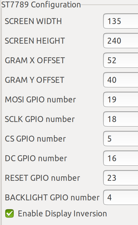
Here are the configuration selections I made specifically for that library:
![]()
The pin numbers come right from the TTGO T-Display pinout diagram. The dimensions are obviously a setup for a portrait mode orientation, but even my rough plans for a UI assume landscape mode. I tried swapping the width and height (and X and Y) values, but that just led to horrible confusion in my little brain. I decided to stick with the portrait mode configuration values and deal with the difference in application code.
Here's the note I left for myself in that application code:
/*
 * The coordinates can be a little confusing. It's possible that I just didn't decode
 * what the library author was thinking. For the TTGO T-Display horizontal with
 * the buttons and USB on the right side,
 *
 * CONFIG_WIDTH  135
 * CONFIG_HEIGHT 240
 * X Offset       52
 * Y Offset       40
 *
 * Point (0,0)     is lower left corner.
 * Point (134,239) is upper right corner.
 * Horizontal text is direction 1.
 *
 * That all seems kind of normal, except that X and Y axes are swapped.
 * So, CONFIG_WIDTH is the height along the X axis. Got it?
 */
I also wrote a little function that draws some colored lines between known points, which I left behind in my code in case I ever need to work it out again. I've implemented most of the UI code already, and things have worked out pretty well. I do have to occasionally re-read that note to myself.
-
Software development environment
04/30/2022 at 17:30 • 0 commentsI'm an experienced professional software developer. In my day job, I use all sorts of fancy tools. Nonetheless, when I returned to fiddling with electronics a few years ago, my journey with microprocessors was typical for hobbyists.
I started with an actual Arduino and the Arduino IDE. That tool and the ecosystem definitely fulfill the mission of making it very easy for beginners to ... begin. It doesn't take long for experienced software developers to get frustrated with the IDE. I'm not complaining about that since I empathize with the IDE's goals. (I also tried the beta of Arduino IDE 2.x and found it kind of a puzzle. I tried it fairly early on, and it was plenty buggy and slow, which I forgive on account of it being an early beta. The puzzle is ... what's the point? If you've outgrown the original Arduino IDE, why not just switch to some other free or commercial IDE that groks the Arduino ecosystem? Well, it's not up to me to tell someone else how to spend their time.)
When I moved along to ESP8266 and ESP32 boards, I continued to code for them using Arduino tools. The board definition stuff that the Arduino project or Espressif or somebody provided is really handy for exploiting the vast collection of Arduino-compatible libraries. You still end up with the setup()/loop() model of an Arduino "sketch", but within that there is lots of library help to do a lot of things.
I've been using Eclipse IDE for Java development for many years. Although Eclipse is most mature as an environment for Java development, it also has plugins to support other languages and various frameworks. For example, PHP and C/C++. In my experience, these vary quite a bit in maturity and features, but at least the Eclipse IDE aspects are familiar. I explored some customized Eclipse environments for Arduino development. They were serviceable, but my recollection is that they felt like works in progress. Some of them have faded away into staleness by now.
I've done a few projects using ESPHome, for example, my Water Watcher project. The idea of ESPHome is to mostly eliminate coding to wire up devices to ESP8266/ESP32 boards. An ESPHome "source" file is a YAML file where you list the sensors you have, their pinouts, and other configuration details. The framework then takes that, generates the C++ code, and then compiles that into firmware for the board. There is still a loop, but it's mostly hidden from you. You can tell it things like "read this temperature sensor every 5 minutes", and ESPHome makes it happen. It's a very nice environment. ESPHome has an "escape" mechanism where you can do custom things in C/C++. Although powerful, it's a bit clumsy to do more than a few lines (mostly I blame the clumsiness on YAML constraints).
But enough about that. I spent some time thinking about whether I could use those environments for this project. It might be possible. I have the intuition that I might have to get pretty deep into the Bluetooth stack in the ESP32 for this project, and I didn't want to get into a lot of bother fighting with my environment. I already know that fairly precise timing can matter a lot for some stages of Bluetooth protocol, and I was afraid of being stymied at some point by the inherent loop structure of Arduino sketches or ESPHome. It is possible to dive down deep in either of those frameworks, but I didn't want to be fighting the framework all the time.
Espressif publishes the Espressif IoT Development Framework (ESP-IDF). I'd been seeing references to it here and there for quite a while and was interested in checking it out "someday". I had somehow gotten the mistaken impression that ESP-IDF was an IDE, and I wasn't anxious to devote a lot of time to learning a new IDE for a hobby project. I'm glad I was wrong about that. ESP-IDF is not an IDE; it's APIs, libraries, and some tooling for developing C/C++ applications for the Espressif processors. Not only is it not an IDE, but Espressif provides plugins for both Eclipse and VSCode IDEs. The documentation for ESP-IDF is very good. Setting it up on top of Eclipse CDT was pretty straightforward. I did have to work my way through some puzzlers in the first few days, but no more so than early use of any sophisticated tooling. There is lots of forum help for finding answers to common problems. My only complaint, which is minor, is that the documentation sometimes points to sample code that has not kept up with the evolution of ESP-IDF, so it sometimes doesn't compile. That's usually easy for experienced developers to sort out.
The ESP32 is natively running a customized version of FreeRTOS. The ESP-IDF documentation for the customized differences is very good. Besides the APIs and libraries made available in ESP-IDF, you can also directly call FreeRTOS functions for managing tasks, timing, and so on.
The bottom line is that I am using ESP-IDF in Eclipse CDT. So far, I have only been writing in C for this project. I haven't decided yet if I will later re-tool things into C++.
-
An easy hardware choice
04/23/2022 at 18:45 • 0 commentsI only spent a little time deciding what hardware to use for this. Like many electronics/maker hobbyists, the idea of Bluetooth immediately triggered me to think of ESP32. And, also like many others, I have a little collection of ESP32 boards already laying around. It would certainly be possible for me to research and choose a cheaper/faster/smarter chipset that was dedicated to a Bluetooth mission, but I'm more interested in learning more about the ins and outs of the ESP32 ecosystem than devoting the effort to learning some other chipset's ecosystem. YMMV.
OK, but which ESP32 board should I use?
- I had a vague notion that BT would work more reliably if I had the original ESP32 dual-core setup. One core is mostly dedicated to protocols (BT and WiFi), and the other core does everything else. I could be mistaken for thinking this makes a difference for this project, of course, but I'm avoiding taking the chance with a newer single-core ESP32.
- I expect this thing will be powered all the time by a USB power supply, so power efficiency of the board is not a big concern.
- Likewise, I expect this thing will be tucked away out of sight most of the time, so aesthetics isn't a huge concern. On the other hand, tidiness does count for something, and I want everything to fit into some kind of enclosure with a minimum of fuss and bother about wiring external components to the processor board.
- Most of the time, the device will be sitting around silently doing its job and being unnoticed. There will be occasional configuration steps (at least for pairing, and maybe for some other things). A display would be nice for doing those configuration steps, and so would some buttons or maybe a rotary encoder. I have a few ESP32 boards with integral (monochrome) displays, and I also have a few separate displays (monochrome and color) that can be easily interfaced to an ESP32 board.
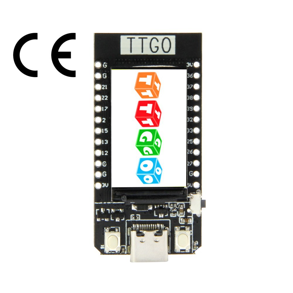
With these vague requirements in hand, I surveyed my existing inventory of parts, and I also went on an Internet window shopping expedition. Before too long, I settled on the popular TTGO T-Display board.
![]()
This board is available in a few "brands" (LilyGO, HiLetgo, and few mystery brands). I think it's a product of LilyGO, and the others are either rebranding or outright rip-offs. I'll probably never know for sure. These boards are available in April 2022 for around US$20 from the usual supply sources. Since I only plan to make one of these (or maybe two if magic smoke appears during development), that's a price I'm OK with. I don't know if it was or will be cheaper before or after the global supply chain disruption. It's available with either 4MB or 16MB of flash. I opted for 16MB because the price difference was negligible.
Besides the usual ESP32 features, this particular board has these nice things:
- Two conveniently located buttons wired to GPIOs. In the picture, you can see them on either side of the USB port. The button the side is the reset button.
- USB-C connector. Actually, I guess that's a very modest inconvenience when I consider how many mini and micro USB power supplies I have laying around.
- Integrated full color 1.14 inch TFT display with a resolution of 135x240 pixels, controlled by an ST7789V chip via SPI.
- Nice and compact, especially if it turns out I don't need to solder on the pin headers.
It has a few other features (like a battery connector) that are not interesting for this project. No wonder this board is popular. It seems well-designed for a lot of possible uses. One thing that might fake you out for a bit is that there is no GPIO-controlled LED on the board. If you try to run the usual blink application to see if the board is alive, it will remain without blinkenlights. There is an LED on the underside of the board, but it's related to power. When powered by USB, the little blue LED is always on. I don't think there's a way to turn that LED off except with a soldering iron or knife.
It's so popular that there are many different designs for 3D-printed enclosures on Thingaverse and similar places. LilyGO also provides a design. If you have access to a 3D printer, you can squeeze one of those out. I don't, so I uploaded the STL files to one of the several online sites that will get it printed and shipped to me. There is an original version of the board and later v1.1 revision. I don't know what the difference is, so I don't know if there is anything to worry about for the physical enclosure. I'm still waiting for mine to arrive, so it's fingers crossed until then. I probably would have opted for the LilyGO design, but I didn't come across it until after I had already ordered something else.
Every place that sells this board points to a copy of the same pin-out diagram, so it's pretty easy to find. If you are used to working with microprocessors, that and the bullet list of textual specs tells you most of what you are likely to care about. There are a few additional items that I figured out empirically. You might or might not need to know these, depending on what you are doing with the board and what libraries you are using.
- The pinout correctly states that GPIO 4 controls the backlight on the display. Unspoken is that HIGH is on and LOW is off. I found out by trying it that you can also do dimming by using PWM on GPIO 4.
- ESP32 has two SPI controllers for our use: HSPI and VSPI. (Apparently nobody knows why they are called that. :-)). The display is controlled by VSPI. (BTW, VSPI is described in Espressif documentation as the 4th SPI interface, so you might think the API constant for it would be 4 (if 1-based) or 3 (if 0-based). It's actually 2 because the first two (internal) SPI interfaces are somehow collapsed in the API.)
- The native resolution of the ST7789 chip is 240x320. To match that up with the physical display with 135x240 pixels, you need to specify x and y offset values. Which is x and which is y depends on the graphics library you are using, along with some other things you tell the graphics library. For the ST7789's 320 pixel direction, you specify an offset of 40 (because (320-240)/2 is 40). For the other direction, the offset is either 52 or 53, depending on how you feel about that half pixel. Depending on your graphics library, you may get truncation of that line of pixels or you may see it as a noise line of random junk.
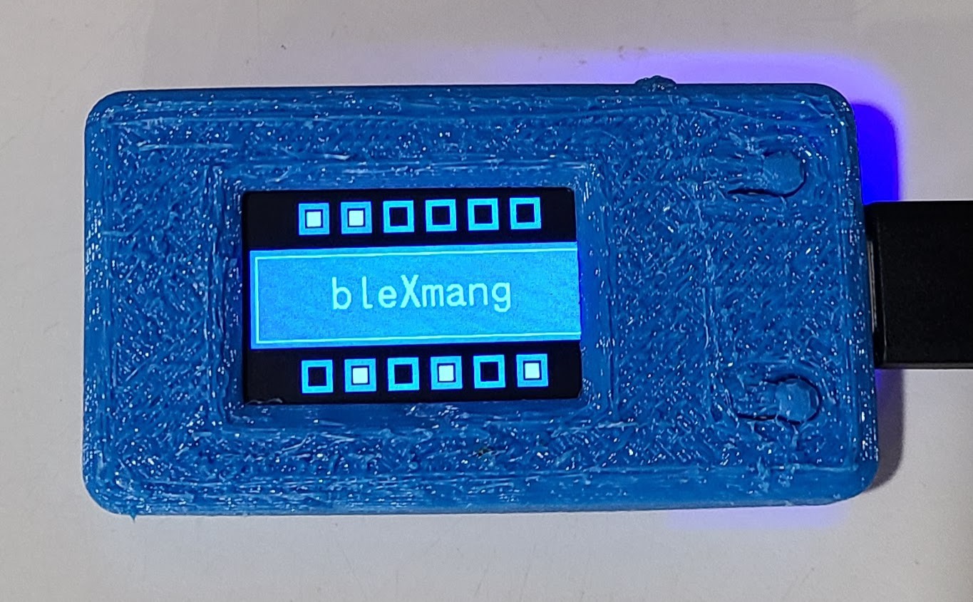
EDIT: The cases. Because I am impatient and because I got a discount for being my first order, I had 2 different case designs printed. One of them definitely did not fit the board, which I imagine might be due to the board revision. The other one fit, more or less, but I didn't really care for the material I had chosen. I picked nylon with a dyed finish, and I just don't like the feel of it. I had a "free shipping" code, so I decided to risk some more money and had the LilyGO design, mentioned above, printed in TPU. Here's a picture of the board in that case:
![]()
The board fits perfectly and the flappy button things work well. The top looks a little rough. All of the other sides are pretty smooth, so maybe the textured top is by design. You can see that it covers a few pixels of the screen on the right-hand side. It doesn't matter for this project, but I might try to trim that edge of the window later. I did move the arrows that point to the buttons on the navigation screen (described in a later project log) a little bit to the left because of it.
The LilyGO case design has no room for a battery, and the bottom cover will not fit into place until you remove the battery connector from the board. The battery connector is soldered in place with some physical reinforcing points, but I was able to remove it cleanly with some side-cutters and fine pliers.
By the way, the service I used to get this printed was CraftCloud3D. If you want to try them, here is a referral code to get 10% off your first order: REFQXAB2XYW. (That's not an affiliate code. It's just a "refer a friend" code, Friend. I have no other connection with them.)
-
BT, IR, HDMI-CEC
04/21/2022 at 16:25 • 0 commentsThe TV controls for both the Fire TV and Tivo remotes use IR since that's the native technology understood by the TV itself. The only interesting part is getting the buttons on the remotes to trigger the emitting of the correct IR codes. Databases of IR codes seem to be a pretty organized thing these days. Our TV is Sony, so it's pretty mainstream.
Besides the BT and IR things, there is one other interesting protocol in the mix, which I mention only to describe how I don't care much for it. The TV and all of my media sources use HDMI. They also all support a feature called HDMI-CEC ("consumer electronics control"). That's a protocol where one device can send commands to another device over the HDMI path. So, for example, the play/pause, fast forward, and rewind buttons on my DirecTV remote can control those functions on my streaming dongles (after I switch the remote to TV mode).
Nice. Well, nice-ish.
Even for my small menagerie of devices, there is a lot of quirkiness in their compatibility with HDMI-CEC. HDMI-CEC also has a limitation on the number of devices that can participate. (It's a limitation of the protocol, not any particular device's implementation.) If you go over that limit, it's hard to predict what will happen. I found that out when one day, after a harmless cable re-arrangement, our TV suddenly refused to connect to our sound bar. After hours of fooling around, I hopped onto my Internet machine and found out about the protocol limit.
The other quirk of HDMI-CEC (or possibly just the devices I happen to have) is that there is sometimes a small but noticeable delay. It's kind of annoying when you do volume up or down and there is a fraction of a second delay before the equipment reacts to it. I guess it's a little bit of Life in the 21st Century, but we have low tolerance for lag, even for things that should seem kind of amazing when they actually happen. But, compare that to 20th century technology, with fewer cooperating things in the path: you'd be stunned if a device didn't react instantly to its volume controls.
I still have HDMI-CEC enabled for all the devices, at least up to what I now know is the numerical limit. But we don't use it for most of the controls. It is nice that, when I press the "Home" button on either of the remotes for the Tivo Stream 4k, the TV and sound bar turn on and the TV switches to the input port for the Tivo. Beyond that, meh. (One surprising and undesired side-effect we discovered was that using the volume controls on the Fire TV remote -- the one being used with the Tivo -- causes the TV to switch to the Tivo input.)
-
An easy workaround
04/21/2022 at 02:15 • 0 commentsHere's the other way I solved the problem, though it's a workaround.
You can only pair a single Tivo remote, but you can pair several non-Tivo BLE remotes with the Tivo Stream 4k. If you try to pair a Tivo remote as an arbitrary non-Tivo remote, it outsmarts you and recognizes it as a Tivo remote anyhow. BLE universal remotes are available, though not exactly plentiful. But it turns out that you can use an Amazon Fire TV remote with a Tivo Stream 4k, and that's what I am currently using as the second remote. There are several models and generations of Fire TV remotes. I got the kind that is "with TV controls" (volume up/down, mute, and power) but without the dedicated streaming channel buttons.
![]()
This doesn't have all of the same buttons corresponding to the Tivo remote, but it does have the ones we use most of the time. Notably, it doesn't have a numeric keypad, but it turns out we don't use that at all. The voice button does prompt the Tivo Stream 4k to listen, but it doesn't pick up any words. Perhaps that's due to some difference in protocol, but we don't use voice searching either. (Call me old fashioned, but all this voice command stuff is a bit too Jetsons-y for me. What next? People using voice to communicate with phones?)
There is some kind of price premium on BT remote controls. I don't know if there is some 3rd party cost involved or if it's just "what the market will bear". When I got my second Tivo remote, it was just as cheap to buy an entire Tivo Stream 4k locally as it was to buy an extra remote (from the Tivo web site) and pay for shipping. So, that's what I did. I've never even powered up the second Tivo Stream 4k dongle. The situation is quite similar for Fire TV remotes. The cost of a remote is not a lot different from buying an entire Fire TV stick. (That's true at least for the BT models. There are some TV sets with Fire TV software built in. Those use IR remotes, and those are pretty cheap. They are also not useful for this purpose.) I was lucky to find someone selling a used Fire TV remote on an auction site.
These device makers have all kinds of tricks up their sleeves, and I'm not privy to most of them. The TV controls on the Tivo remote for the Tivo Stream 4k work with my TV. (I don't remember if I had to do something to make that work. Probably.) The Fire TV remote that I had for my Fire TV dongle also controls the TV correctly. The replacement Fire TV remote did not control the TV at first. So, I paired it with my Fire TV dongle as an additional remote (hey, an additional device-specific remote ... have as many as you want, what a concept!) and went through a painless procedure to teach it about my TV. Then I unpaired it from Fire TV and paired it with my Tivo Stream 4k. Hey, presto: TV controls. I could not find a way to teach it about my TV via the Tivo Stream 4k user interface.
Using that Fire TV remote with my Tivo Stream 4k works well enough for me, and it takes away the time pressure for implementing blexMang. I let my couch partner use the original Tivo remote so I don't have to send them to re-education camp.
-
The motivating itch
04/21/2022 at 01:56 • 0 commentsWe have a Tivo Stream 4k dongle on our TV. It's a nice enough device in the Android TV family. We use it enough that I bought a second remote for my couch-based co-conspirator to use. Then, one day, some software update or other imposed the limit of a single Tivo remote to work with it.
If you pair a second Tivo remote, it loses its pairing with the first one. I fiddled with that for quite a while before I figured out what was going on. Tivo used to have a FAQ item that said you could use multiple remotes, but they changed the answer from "yes" to "no". Problem solved (for them). I assume they had some technical reason for putting that limitation in place. In fact, it might be a limitation put in place in some Android TV base platform update they got from Google. Beats me.
The important part is that that change made me sad. I started thinking about ways to be able to use both remotes, and that led to the bleXmang idea. I have quite a few low-cost BLE boards laying around, but I'm by no means a BLE or BT expert. It seems like some technically interesting stuff, so I'm plowing ahead with it even though I have partially solved the problem another way (see the next project log item).
Use cases for a single remote being used with multiple target devices are a little harder to come by, unless maybe you own an electronics showroom. But I think the techniques I plan to use for multiple sources will extend fairly easily to multiple targets, so ... why not?
bleXmang
BLE MITM Group. It's pronounced the same as "blanc mange", the dessert, but it's nothing like that.