Maximiliano Palay
-
Actuators
05/08/2022 at 19:45 • 0 commentsThe actuators are a fundamental part of this project. One actuator could be custom designed for each joint, this would possibly provide benefits regarding mass and volume. To reduce complexity and manufacturing costs, the same actuator is used for both joints.
To achieve the actuator concept, inexpensive hobby drone motors are used in combination with [the cheapest] ball screw reductions. After having the physical motors on hand, I partially modeled them as accurately as possible. The CAD models aren't available on the internet. The center hub with the bearing seats was not modeled due to the fact that I already knew it would have to be removed.

Original EA65 brushless motors. To achieve the concept, the motors have to be modified in order to allow the screw to pass through, and the ball nut has to be attached to the rotor in some way. The resulting axis has to be bore. Furthermore, the stock bearings aren't meant to handle high axial forces, so these have to be changed for others which allow this. To handle this axial forces, new angular contact ball bearings are placed. These come in a pair arrangement and there is a specific way to mount them.
The design process was iterative. I created a first generation model with modifications, printed a 3D mockup of it, and exchanged ideas with the machinist that would perform the modifications and manufacture the new pieces. The first generation actuator involved creating an entirely new rotor with included axis, which would incorporate the section of the original rotor which holds the magnets. Several instances with the machinist were required before achieving the final design. He gave insight into what design aspects made the costs lower and reduced fabrication complexity.

3D printed mockup of the actuator. The final design retains the original rotor, and new pieces are created, such as a new axle, bearings seats and what I call the rotor assembly crown, which presses the assembly together using 6 M2 screws. The crown gets its name because of its shape, and the shape is such because it allows for the mounting of the encoder disc. The ball nut is held through 4 M4 screws in a sandwich configuration which presses the new axle, the rotor and the nut together.

Actuator design, assembled view. The actuator modifications turned out to be quite complex. If I could go back in time, I would purchase a frameless brushless motor and design from scratch the necessary parts. At the time, frameless motors with the desired characteristics and price were not found.
-
Design Concept
04/27/2022 at 12:50 • 0 commentsEvery product starts with a concept, an idea.
This was the case for the mechatronics design. Taking the actuation principle observed from MIT TF8, the concept shown in the following picture was conceived.
Another video of a similar actuator is attached here.
It is important to mention that for this project, elastic elements are excluded for simplicity and components minimization.
![]()
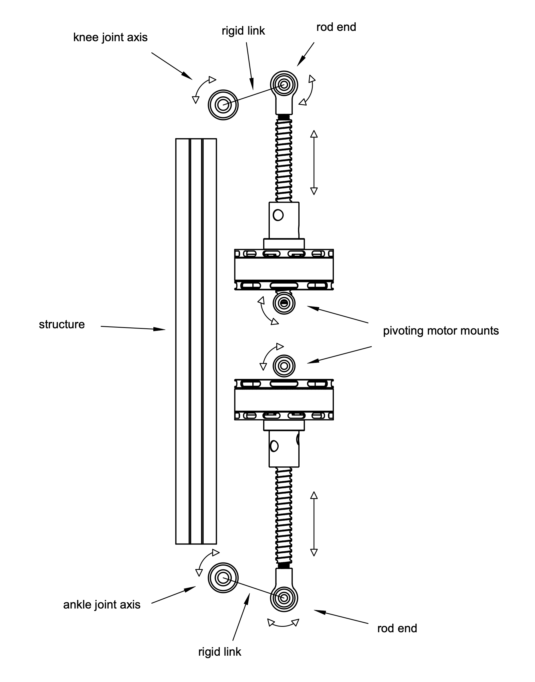
Motors on their own are unable to provide the required specifications. Combined with ball screws, the resulting actuators enable tuning to accomplish the needed properties. The actuators are mounted over pivoting mounts, and the screws pass through the motors' axes. These screws exert a linear force over a lever mechanism, which translates linear motion into torque at the joints' origin. This lever mechanism is what allows for reduction tuning, by modifying the properties of the rigid link portrayed on the image.
There is a structure, represented by an aluminum profile on the image, which holds everything together including the electronics.
The exclusion of elastic elements enables the system to know its position by using a forward kinematics model, thus without the need for joint encoders.
-
Inspiration
04/22/2022 at 15:27 • 0 commentsThe interest on bionics first shined through when I came across a TED talk video of Dr. Hugh Herr on 2014/15. Hugh, who is a bilateral amputee and a professor at the MIT tells his story. It is immensely inspiring how he took on his life after the accident. He is pushing technology forward to enable better bionics, which help himself and others.
It's impossible to ignore the fact that during the whole talk, he is wearing two bionic limbs, which he proudly shows off. Being 16 years old at the time, I couldn't stop thinking, "how cool!". The BiOMs are able to produce power on their own, and assist him during walking and a small run test, just as if he had both his biological legs intact.
On a more recent date, a video telling the story of Everett Lawson, a research assistant at the MIT Media Lab, came up on my YouTube feed. Of course, with such a title, I had to watch it. Everett's life story and his commitment to create better technology are equally inspiring.
At one time in the video, Prof. Hugh Herr, Director of the Biomechatronics Group is introduced. The same man from that 2014 video!
Several prototypes from the Biomechatronics Group are shown which have varying sizes, designs and mechanisms. It pretty much looks like a shelf of movie props, kind of for a sci-fi movie.
Matt Carney, at the moment a PhD candidate at the MIT Biomechatronics Group participates in the video presenting his thesis work, a bionic actuator configurable as a knee and/or ankle prosthesis, for which Everett was a testing subject. His work included hobby grade brushless motors, ball screws, electronics, components which looked quite familiar to myself.
After this I began getting into topic, reading Matt's thesis, previous work from Hugh, and getting to know a bit more on the prosthetics world. What's available, what are the costs, how does Matt's work compare, different levels of functionality were all questions that popped up.
Other institutes such as the University of Michigan and UT Dallas have their work on this subject as well. In the following video, Eng. Chris Nesler and PhD student Kevin Best demo a robotic prosthetic leg. It was developed at the Locomotor Control Systems Lab under the direction of Prof. Robert Gregg.
I've been working on hobby robotics projects for quite some time, built UAVs, wheeled and tracked robots and have used several of the components I had seen on videos (of course much much more hobby grade than what Matt used). Being familiar with the technology and seeing the impact of such projects made me wonder if I could make something affordable out of known and previously used components.
The idea of attempting to make a bionic prosthesis kept growing on me.
Affordable bionic prosthesis
This project aims to create an affordable lower limb prosthesis for above knee amputees using hobby grade components.