-
1Aquire materials
I've included all of the materials I used in the components section.
Other than the case and some of the electronics, all other components can be substituted with a similar item with a little fore thought.
Even so I've done my best to give as much detail as I can, your mileage may vary.
This step is listed first as you can often start working on the project with what you have on hand while waiting for other parts to arrive.
-
23D Print Components
Parts To Print
PART MATERIAL METERS TIME* Speaker Covers Black PETG 1.50 14m Power Grid Cover
Isolinear Chip Bay CoverBlack PETG 25.41 6h5m Power Grid Tray Black PETG 8.30 2h19m Isolinear Chip Tray Black PETG 32.42 9h18m Isolinear Chips x12 x6 TL Blue PETG
x6 TL Green PETG10.03
10.037h8m
7h8mMimetic Crystals x3 TL Blue PETG
TL Green PETG
TL Red PETG0.88
0.88
0.8835m
35m
35mPADD Bottoms
PADD Controls
PADD TopsSilver PLA
Yellow PLA
Silver PLA16.98
0.69
16.156h50m
15m
3h22m* Print time & meters of filament is from GCODE generated for a Prusa MK3S
Source: 3D_Prints.zip
Total Filament Used
MATERIAL METERS Black PETG 67.63 TL Blue PETG 10.91 TL Green PETG 10.91 TL Red PETG 0.88 Silver PLA 36.10 Yellow PLA 0.69 Printing Tips
Speaker Covers
Print with grill facing down at 0.20mm layer height. No supports needed.
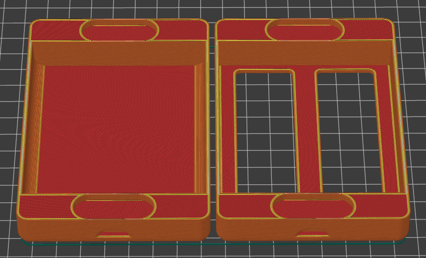
Power Grid & Isolinear Chip Bay Covers
Print with top of cover facing down at 0.20mm layer height. No supports needed.
Power Grid Tray
Print so that the visible surface with the USB C slot is facing down at 0.20mm layer height. Will need supports
Isolinear Chip Tray
Print with the notched surface facing up at 0.20mm layer height. No supports needed.
Isolinear Chips
Print with large surface to print bed at 0.20mm layer height. May need to add supports for the slot at the bottom. Print two sets each in a different color of translucent filament.
Mimetic Crystals
Print in vase or continuous mode at 0.10mm layer height. Ber sure to add a pause after the first few layers so that you can glue the RFID token to the inside bottom of the crystal. A drop of super glue worked well.
PADDs
![]()
Print the PADD controls first in the color of your choice. Then without removing them from the print bed, switch the filament and print the PADD tops directly over the controls with the top facing down.
Print the PADD bottom with the bottom facing down. All parts print well at 0.20mm layer height.
Print two PADDs.
-
3Laser Cut Pieces & Glue Mounting Panels
Parts to Laser Cut
Material Used
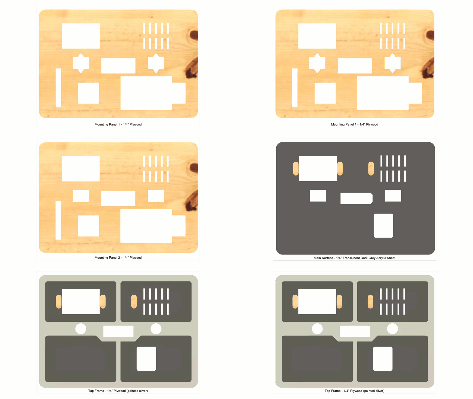
MATERIAL SIZE 1/4" Plywood 12" x 24" 1/8" Translucent Dark Grey Acrylic Sheet 12" x 24" Main Panel
The panel is made of 4 1/4" layers of material glued together. I mainly chose 1/4 material because it was the thickest material I could reliably cut with a diode laser cutter.
- Mounting Panel 1 - 1/4" Plywood
- Mounting Panel 2 - 1/4" Plywood
- Main Surface - 1/8" Translucent Dark Grey Acrylic Sheet
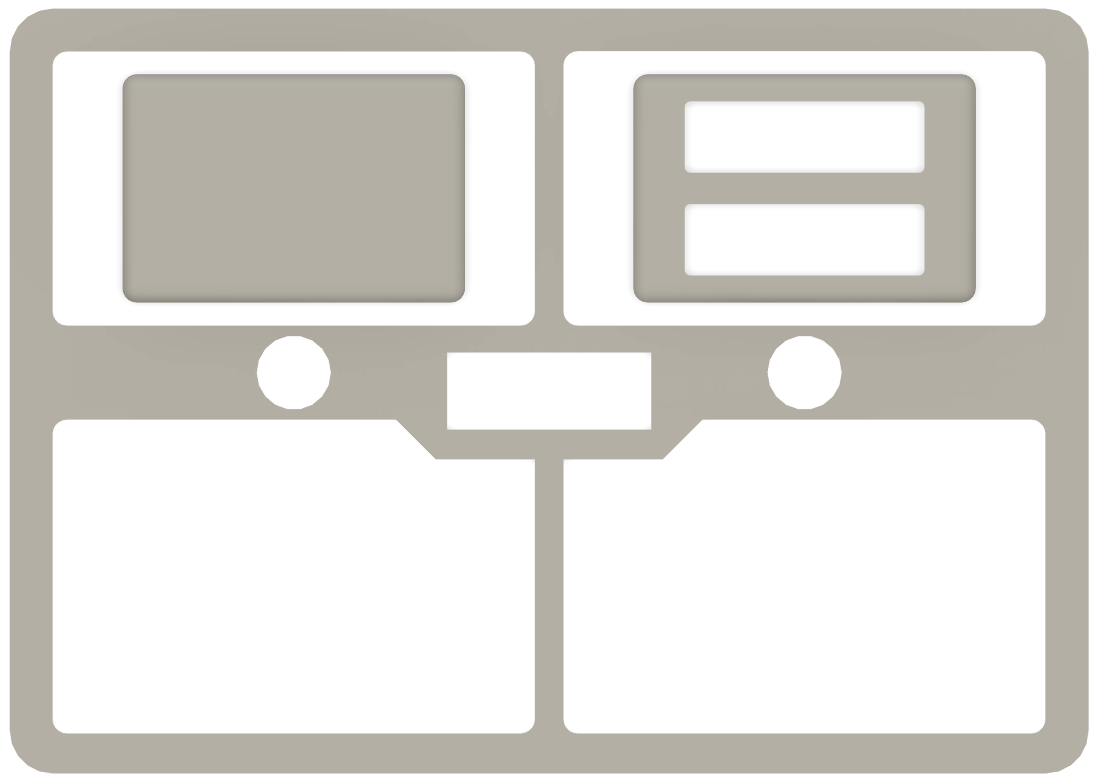
- Top Frame - 1/4" Plywood (painted silver)
![]()
At this step It may be a good Idea to glue the two mounting panels together with some wood glue and several clamps. Then set it aside to finish later, in another step.
PADD Displays
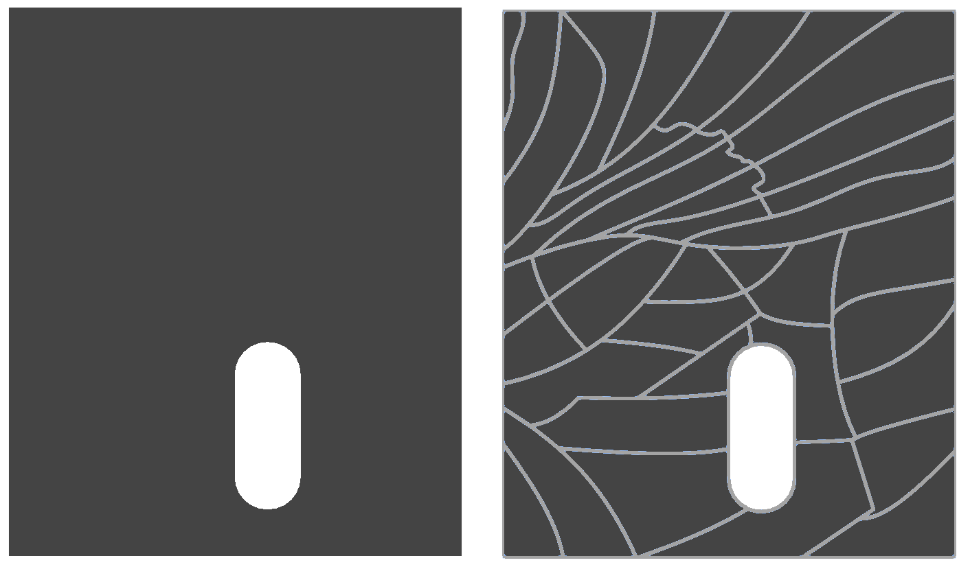
You'll need two PADDs, one solid piece, and another cut to look like a puzzle.
Don't cut out the puzzle lines yet, you'll want to apply the vinyl text first.
Source: laser_dxf.zip
-
4Paint Components
Now that we have all all of the parts we can paint.
I tried to keep the pieces that needed to be painted to a minimum. So the only pieces we need to paint are the top pieces, and they are all painted silver.
- Top Frame - laser cut 1/4" plywood
- Power Grid Cover - 3D printed PETG
- Isolinear Chip Bay Cover - 3D printed PETG
-
5Fab PCBs
Circuit Board Etching
![]()
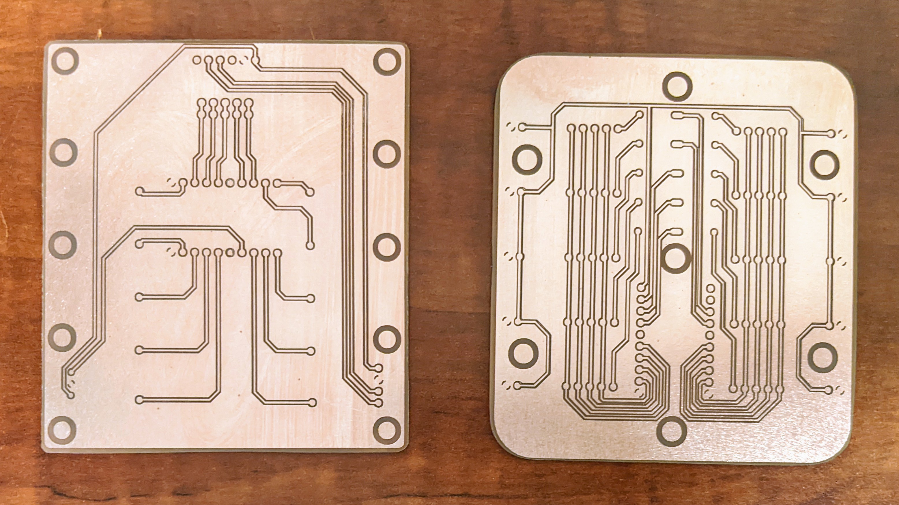
I found it easier to use the laser to create a circuit board than trying to use a more conventional transfer method.
You can find details in my Etching the Circuit Board Log.
I didn't apply solder mask and just used the bare PCB's.
Drill out holes
Drilling out the holes is the most tedious task and requires a drill press or a very steady hand and a dremel tool.
While I used a drill press, I still didn't drill the tiny holes perfectly.
Solder components
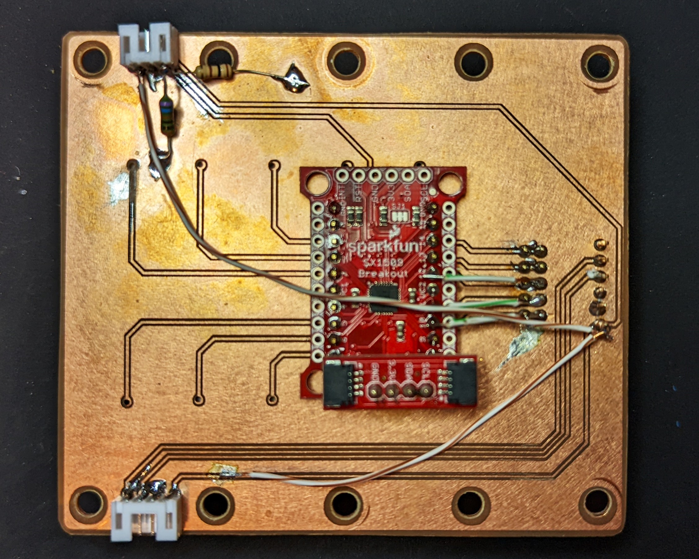
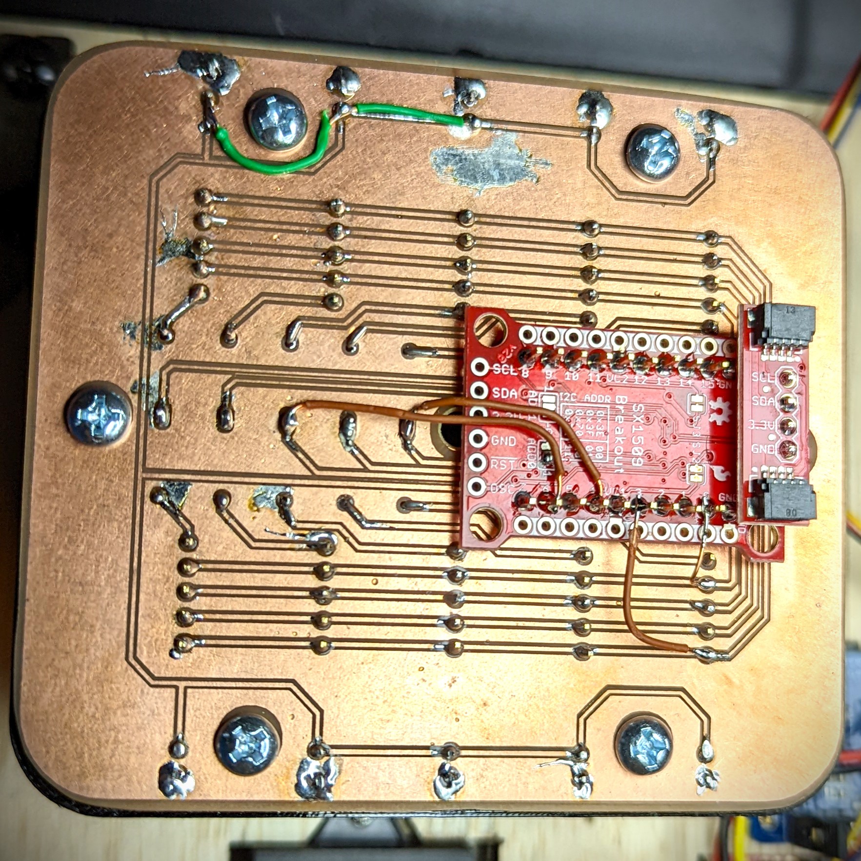
Because of a few reason (cheap copper boards, imperfect drilling, no solder mask) I ran into trouble soldering the bare PCBs. The solder pads weren't quite big enough and most of the pad surface was removed when drilling the through holes.
So I ended up having to run wires to bypass some of the broken traces. And for the power grid I ended up not using the traces for the IO pins. Instead I used the same pins for the IO board and just cut the unused ones short.
Power Grid
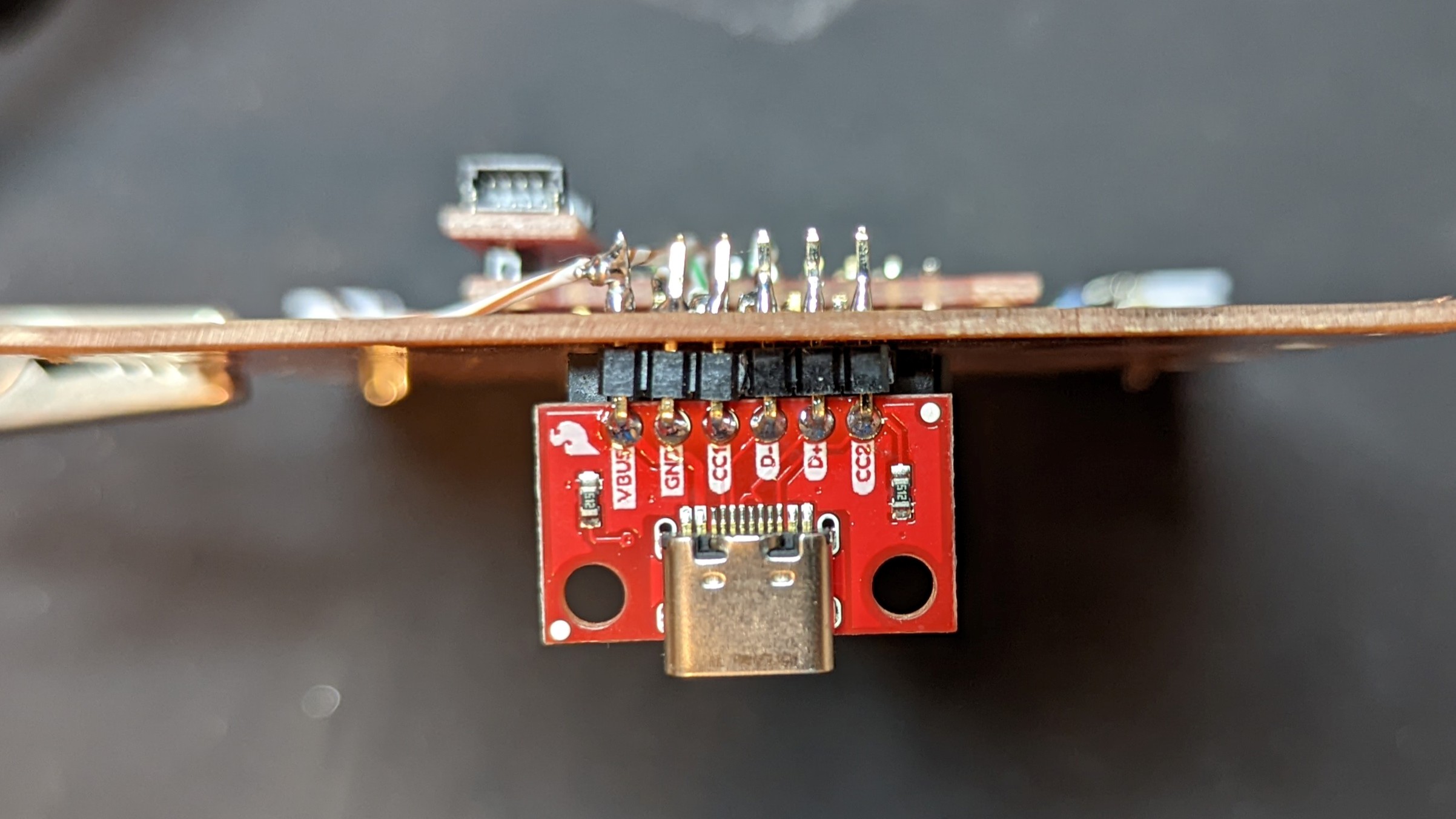
The power grid supplies power to the whole system through a USB C port and two connectors.
It also contains a 16 OUTPUT I/O EXPANDER BREAKOUT with a QWIIC adapter to read the wire states.
Isolinear Chip Grid
This board allows the system to read the slot and value of each Isolinear chip inserted. It also uses a 16 OUTPUT I/O EXPANDER BREAKOUT with a QWIIC adapter.
The board I designed for this had several issues:
- LED's lighting had very little to no effect.
- They would need to be mounted at the top somehow to work.
- I didn't design it with the right number of pins per Isolinear chip.
Despite these issues, I was still able to get it to work by shifting the whole board to one side by one pin when mounting. I also then had to file part of the Isolinear chip tray slots to make up for the shift.
- LED's lighting had very little to no effect.
-
6Assemble main panel
Now that the rest of the main panel is ready, we can assemble it.
You should have already glued the bottom plywood pieces together in step 3.
Prep Acrylic
To give the top two sections a different look and feel, you can lightly sand those sections with some 250 grit sand paper.
Also to prevent other stray light from making it through the acrylic sheet, you can cut some vinyl to blackout everything except the LED bar. Use the file main_surface_mask.studio3 in the vinyl_art.zip
Glue Other Panels
I used Super Glue to attach the top frame to the main acrylic surface and to the the mounting panel. Since Super Glue has a very short working time, I glued the main acrylic surface to the mounting panels first. Once that dried I glued the painted top frame to finish the main panel. It's not as noticeable in person, but in the photo below you can see how a placed the super glue drops under the sanded acrylic. The vinyl surface mask applied earlier also helps to hide those glue drops.
Attach Trays & PCBs
The trays line up very nicely with the openings. you can insert some Isolinear chips into the slots to help align the tray. Align the screw holes for the PCBs and the trays then insert a few screws to keep everything in place. The panel should now look like the animation below.
![]()
Attach Magnets
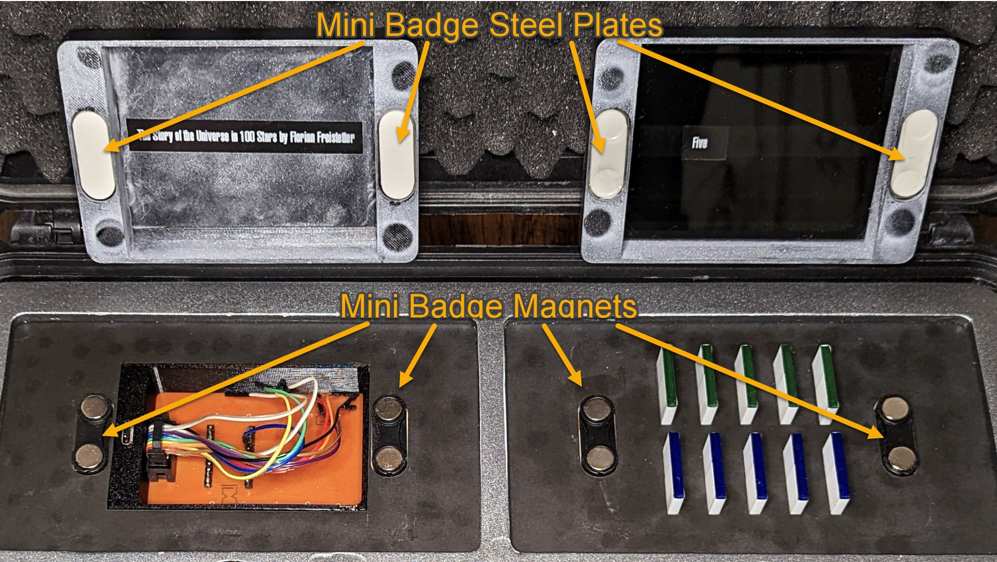
To keep the covers in place I used some mini name badge magnets, as the came with both the magnets and the steel plates. The magnets should be glued to the main panel, and the steel plates to the covers. I found that the magnets were a bit too strong. A simple fix was to just glue the steel plates on upside down, so the adhesive pad it came with faces the magnet. You can then just leave the wax paper on, or peel it off an cover with thicker material to adjust the hold strength.
![]()
-
7Apply Art
Vinyl Art
All of the art was was created with vinyl to give the panels a nice crisp contrast. I used a Silhouette Cameo cutter for all my art, so all the files I have are Silhouette Studio files.
Panel Art
I used different colors of vinyl to apply the artwork to the panels. There's no fancy method, just follow the standard procedure for applying vinyl to any surface, and apply one color at a time. To help align the status indicators you will want to attach the LED bar and turn on the segments while attaching those labels.
![]()
PADD Art
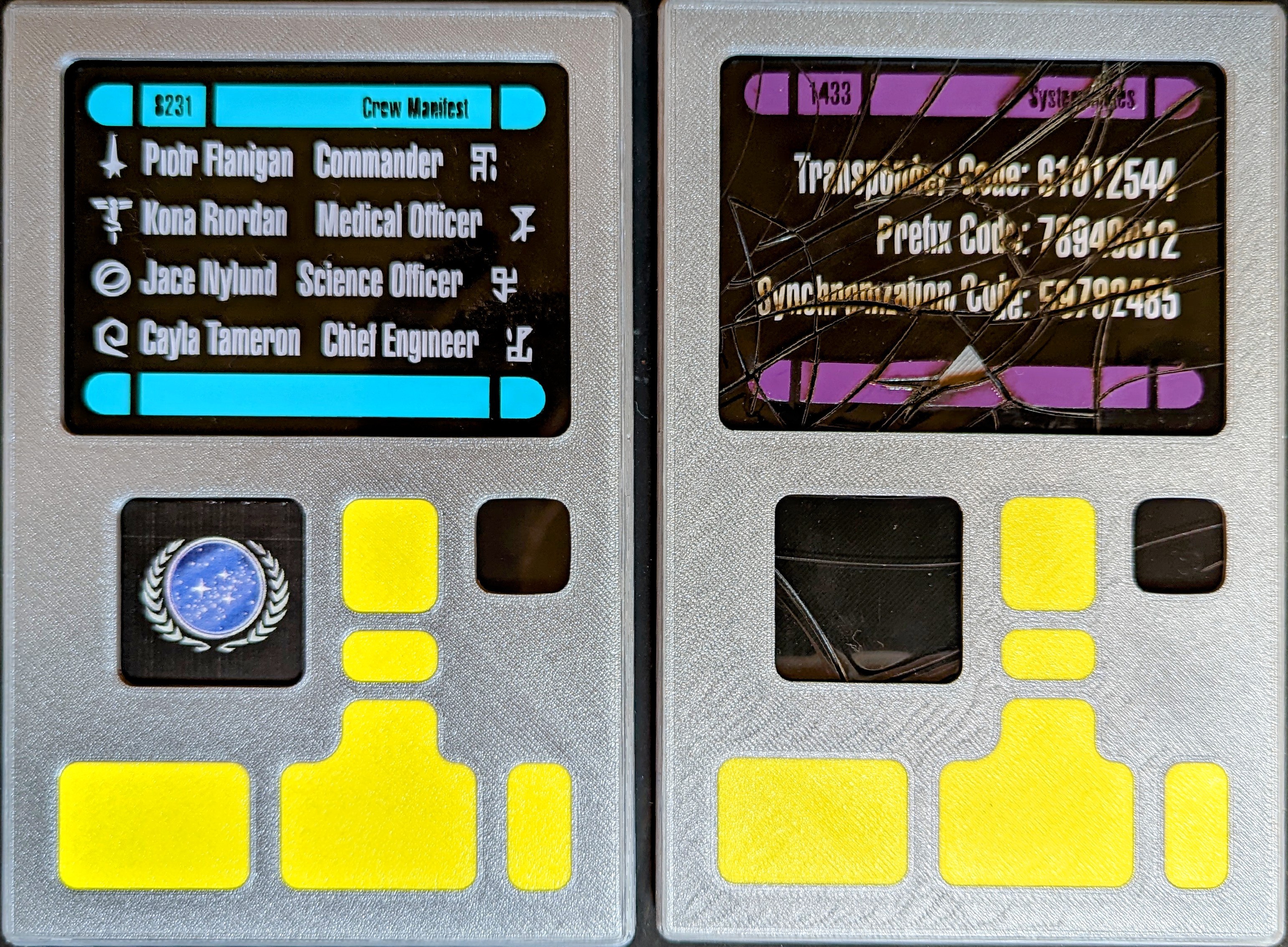
Follow the same procedure for the PADDs. You can also add a sticker to the lower left portion of the display that will be visible through a smaller window. Once you apply the art for the second pad (System Notes) you can use the puzzle dxf to cut the display into a broken screen.
To finish the PADDs you can glue the magnets to the bottom and the metal strip to the top. Then insert the PADD display into the bottom, and put the top in place.
The PADDs are now finished! -
8Attatch & Wire Electronics
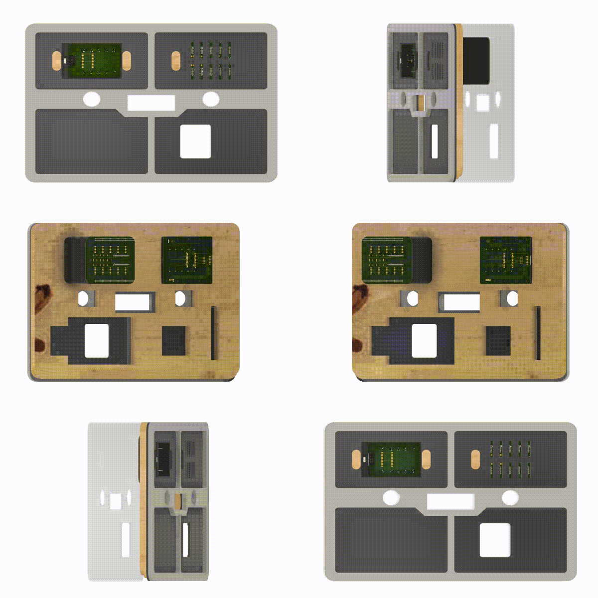
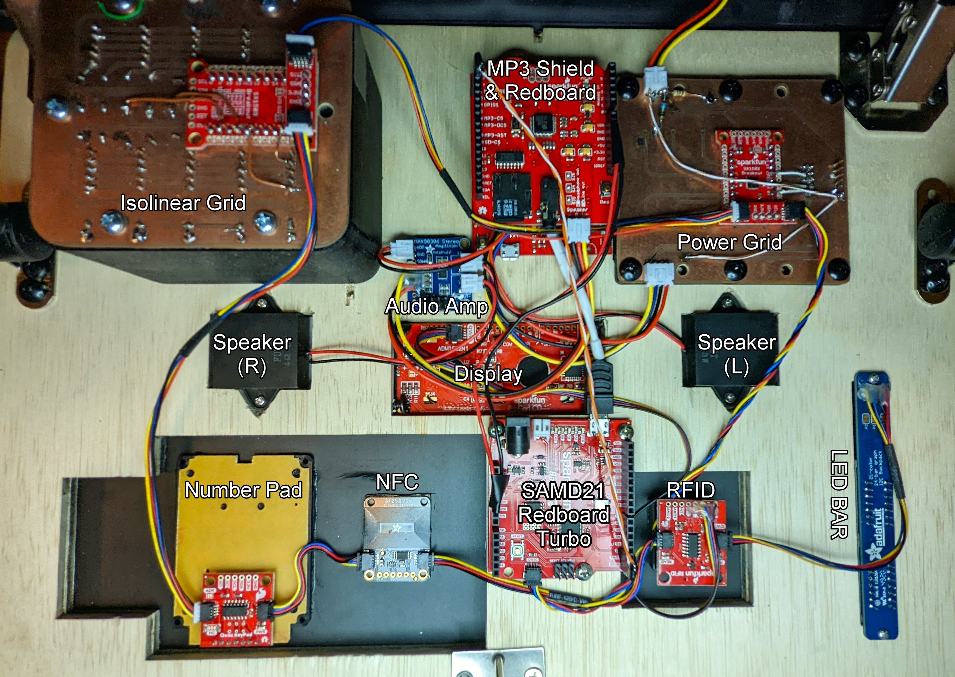
This part is quite a bit involved as there are so many components. To simply things quite a bit I used as many I2C devices as I could and used Sparkfun QWIIC connectors as much as possible. You'll also notice that the mounting panel is designed so that most of the electronic components only fit one way in specific locations. This should help figuring out where everything goes.
![]()
Upside down bottom view. Only way to access the electronics if already mounted in the case. QWIIC (I2C) Connections
The QWIIC wire connection order above is:
- LED Bar
- RFID
- Display
- NFC
- Number Pad
- Isolinear Grid
- Power Grid
- Redboard Turbo
The only items that needed a QWIIC wire soldered to them are the LED bar and the RFID reader to connect to the display.
Audio System
This could have been a QWIIC system but I wanted to use the parts I had on hand.
I had an MP3 Shield and would have just used the Redboard Turbo to drive it, except it doesn't support the Arduino library provided for the MP3 Shield. So I used a regular Redboard (Sparkfun's Arduino UNO) just to run the audio.
One other reason for doing it this way was because the library for NFC module from adafruit only worked on the Redboard Turbo. (Something else I didn't realize in my initial design)
You'll want to flash the serial_audio_controller code before mounting it. Now would also be a good time to upload all of the audio files to an SD card and insert it into the MP3 shield.
Then connect the MP3 Shield output to the Audio Amp input, and plug the speakers in as well.
Now we can run some solid core 22AWG wire between the MP3 Shield and the Redboard Turbo. You'll need 4 wires. Connect the GNDs and 5V ports together, and then the Tx - Rx on each as well.
-
9Programming the System
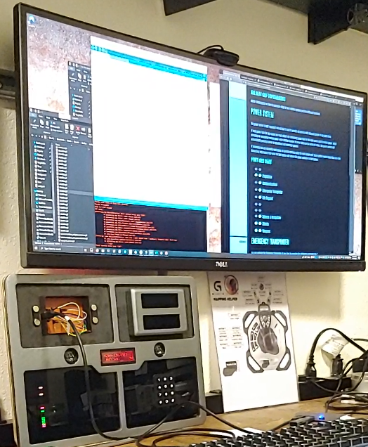
And now the fun part! since we haven't mounted the panel to the case yet you can set it on your desk and work on programming the Redboard Turbo via the USB-C port in the power grid system.
Now you can upload the star_trek_escape_box code and start testing.
My Software Development Setup -
10"Programming" Isolinear Chips
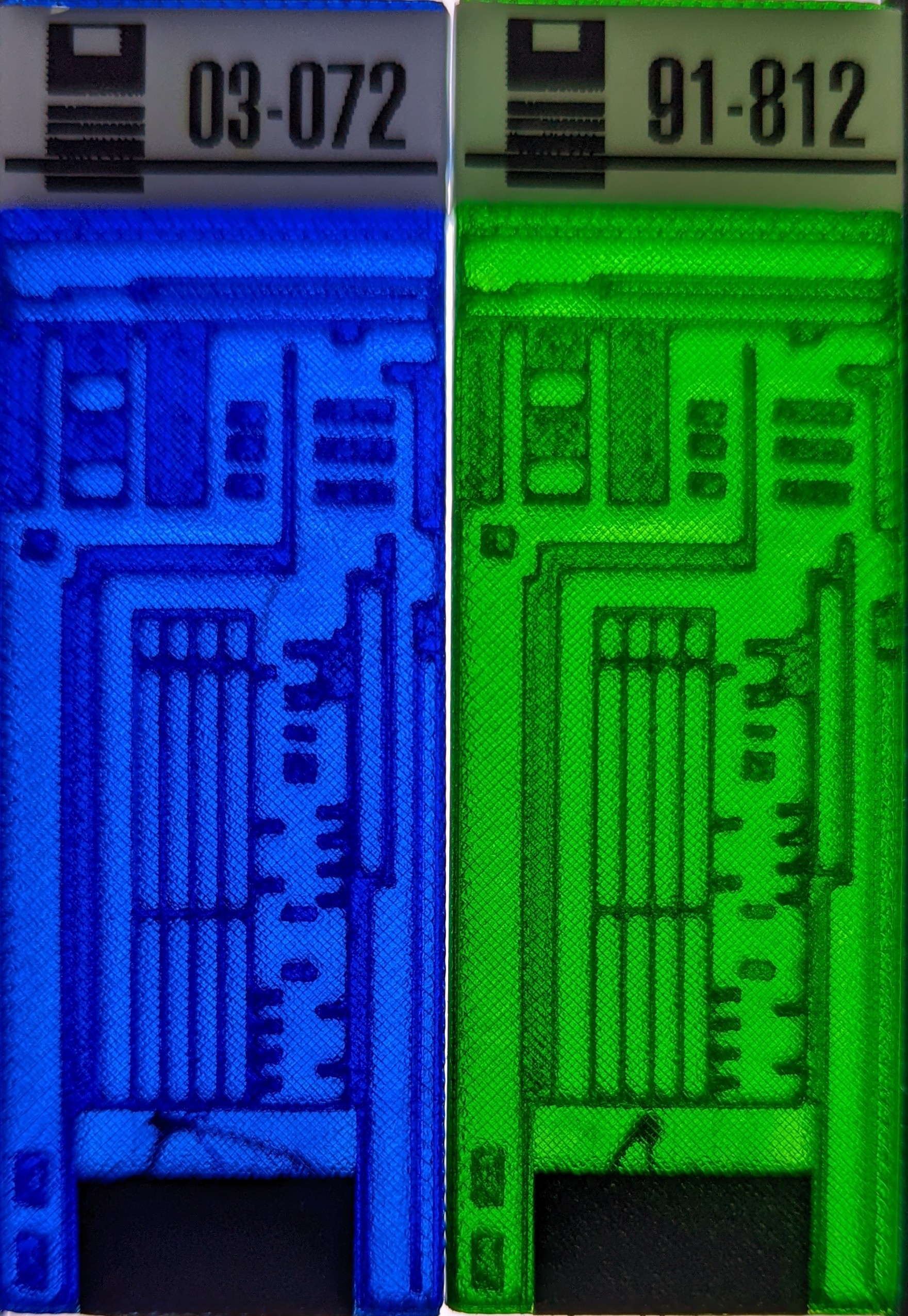
I really like how the Isolinear Chips turned out. They look especially neat when you hold them up to a light.
I was able to print the chip labels using a brother label maker.
![]()
"Programming" them is also pretty simple as you can set each Isolinear Chip to represent a certain number in binary. This is done by shorting the GND pin to the other pins to represent 1s and 0s. Don't get to caught up in the design, just think as all opens are 0s and shorts are 1s, even though it'll be backwards in the software.
Also since the Isolinear chip grid only uses 5 pins and the Isolinear chips have 6 pins there is one pin that is not used. Also the GND pin is the inner pin between the rows, so it's on the right for the blue chips and left for the green chips. This also limits the chips to a specific row. All the green Isolinear chips must be in the second row (back row), and the blue Isolinear chips must be in the first row.
Another limitation in my Isolinear chip grid design is that each chip needs to have a unique short sequence. Meaning that each chip cannot share a 1 bit with another chip in the same row. While this severely limits the number of option each Isolinear chip can be, it was good enough for my needs.
In the software, I ended up reading the value of the Isolinear chip as the location of the bit that was set high.
N - Not used, G - Ground, 1 - Short, 0 - Open
Because I mirrored the pin lines in the PCB design, the blue chips are read as big-endian, and the green chips are read as little-endian.
Blue Chip Blue Bin Blue Dec Green Chip Green Bin Green Dec 03-072 N1000G 1 91-812 NG1000 4 08-041 N0001G 4 39-024 NG0010 2 14-328 N0100G 2 43-524 NG0100 3 03-853 N1000G 1 53-308 NG0001 1 16-151 N0010G 3 97-362 NG1000 4 24-713 N0000G 0 94-347 NG0000 0
 RubenFixit
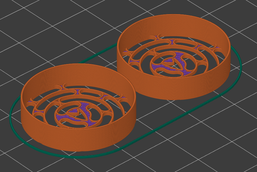 Print with grill facing down at 0.20mm layer height. No supports needed.
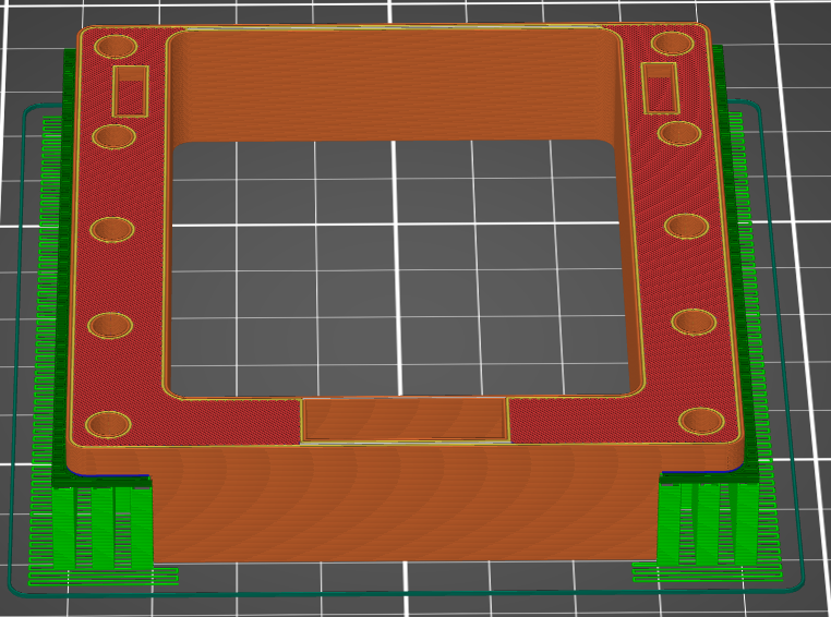 Print so that the visible surface with the USB C slot is facing down at 0.20mm layer height. Will need supports
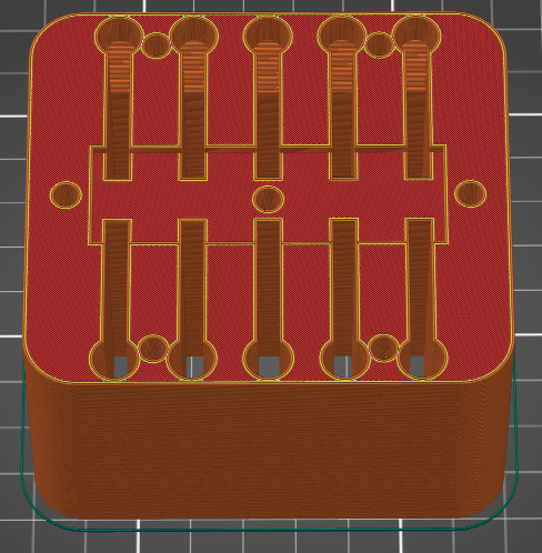 Print with the notched surface facing up at 0.20mm layer height. No supports needed.
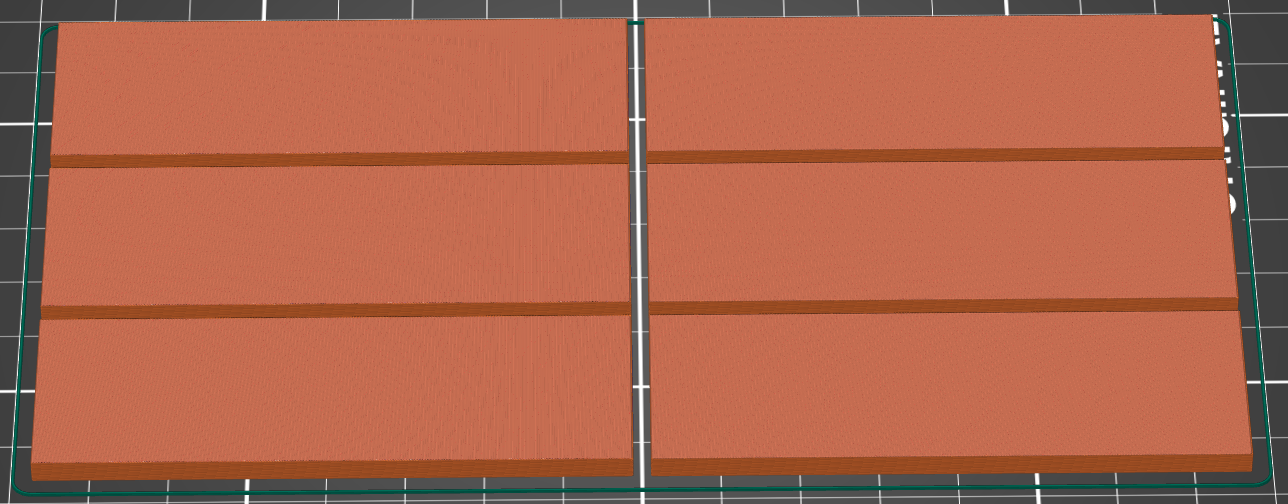 Print with large surface to print bed at 0.20mm layer height. May need to add supports for the slot at the bottom. Print two sets each in a different color of translucent filament.
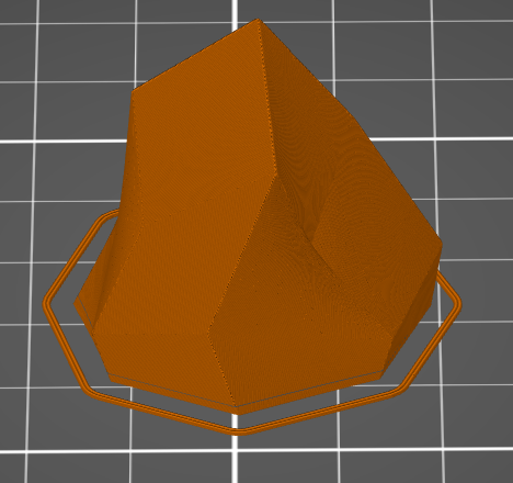 Print in vase or continuous mode at 0.10mm layer height. Ber sure to add a pause after the first few layers so that you can glue the RFID token to the inside bottom of the crystal. A drop of super glue worked well.
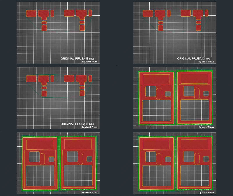
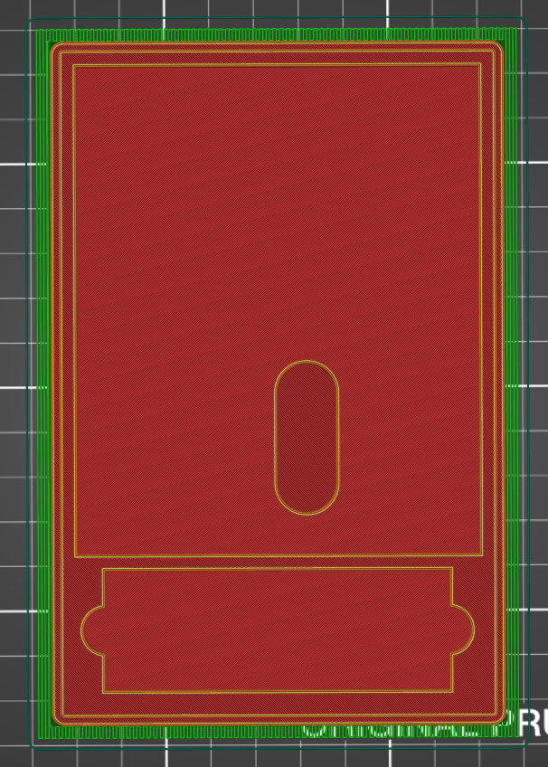 Print the PADD bottom with the bottom facing down. All parts print well at 0.20mm layer height.


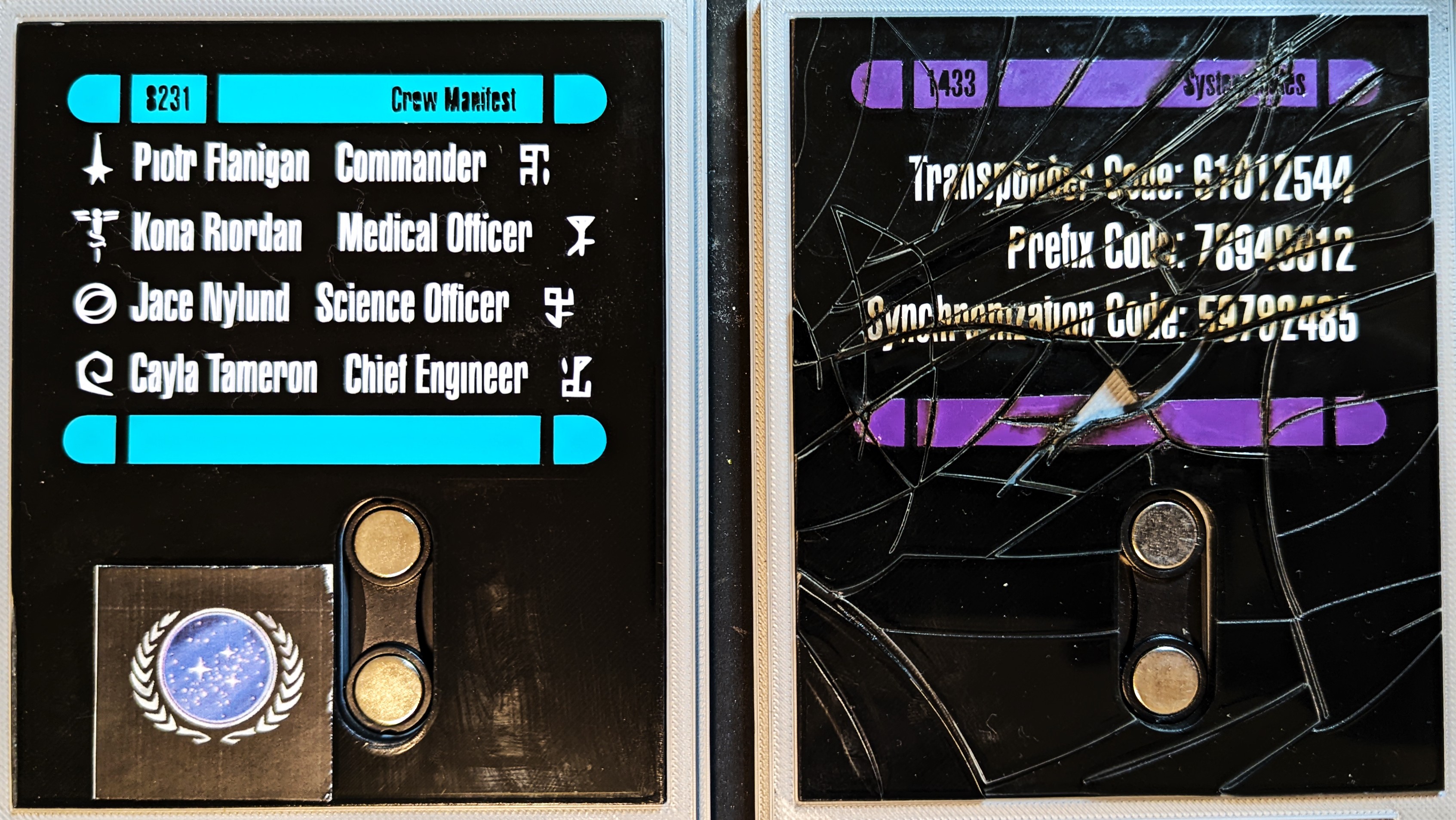 To finish the PADDs you can glue the magnets to the bottom and the metal strip to the top. Then insert the PADD display into the bottom, and put the top in place.
Discussions
Become a Hackaday.io Member
Create an account to leave a comment. Already have an account? Log In.