JP Gleyzes
-
final video #HackadayPrize
10/20/2022 at 18:43 • 0 commentsHere is the final video for this project.
It was a lot of fun, I learned a lot. Proud to be one of the finalist !
-
scaling up the linear actuators
10/12/2022 at 11:37 • 2 commentsWhen I made my quick market analysis, I came to the conclusion that the critical parts in terms of cost will be the mechanics and more precisely the linear actuators.
Of course this project can be considered as completed for my initial specifications. But if I want to make a "bigger" solar tracker then I will have to face the issue of affordable actuators.
![]()
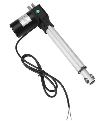
These little babies, when strong enough, are in the range of 150-200€. Furthermore they are provided with simple end of motion switches but no way to get their precise positionning (no encoder)...
And when we search for this kind of actuator with a control loop, we easily go in the range of >1000 $ systems... Which is a show stopper for my use case...
So I decided to make my own servo motor using scavaged wiper motor.
It is explained in another project here : how to convert a wiper motor into a strong servo motor
This means that we have now a 20$ servo motor able to produce torque up to 60 Newton Meters (Nm) or if you prefer more than 600 kg.cm... Well enough to move a solar panel!
A wiper motor is in the range of 20€, the driver 5€, the AS5600 5€ more... A full system for 30€
Considering this achievement, I do believe now that my solar tracker could be easily scaled up for much bigger panels. And almost at the same target price than when using stepper motors !
-
publishing V3 source code for firmware and Android App (new azimut axis)
10/11/2022 at 19:04 • 0 commentsAs promized, here is the source code for:
- The SolarTracker firmware V3 : SolarTracker on my Github
- The Panel Orientation Android App : PanelOrientation on my Github
Don't forget to donwload the V3 of these files.
As usual, if you prefer to download the Apk it is here!
They work together and allow to ease the Solar Tracker Initialization. Needed for the new azimut axis mechanics.
Full details into this log
Both the firmware and the App allow this behavior during calibration :
And finally this behavior during a timelapse filmed in september between 14 pm and 18 pm (or 12 UTC to 16 UTC). The panel follows the sun and when elevation reaches 20° (shadows coming close to the panel) it performs the flip maneuver from West to East for the next morning.
This movie has a speed increased by x480 and thus represents 4 hours in real time. It was a moderate windy day, we can see that the new azimut axis is working without problem.
-
A new calibration procedure
10/05/2022 at 09:03 • 0 commentsIntroducing the new Azimut mechanics induced a side effect... My manual calibration procedure no longer worked for this axis.
This is due to the fact that:
- the azimut motion is no longer linear and follows complex motion equations
- the azimut bottom plate should be pointing to the south
So I decided to implement a new procedure of calibration into the Android application. Don't panic it is even simpler than before!
- launch the App
- put the phone on the ground parallel to the bottom plate and align the North (this calibrates the bottom plate)
- put the phone on the panel (bluetooth enabled)
- press the ESP32 reset button
- the ESP32 automatically connects to the phone and gets the time and the location (as previously)
- now push the "find Sun" button, this will send the current Elevation and Azimut angles to the ESP32
- quit the App to resume normal tracking mode.
Here is what you should see on the screen
![]()
And the panel will rotate to the right position, pointing to the sun !
This should be done only once after powering the ESP32.
Once done this calibration will be kept into the memory of the ESP32 (even during night).
-
New Azimut: equations of motion
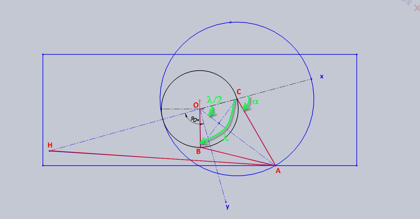
09/30/2022 at 14:23 • 0 commentsLet's have a closer look at the geometry of the Azimut axis
![]()
- H, O and C are aligned on the x axis of our frame centered in O
- OC = OB = R
- BA = CA = 2R
- alpha is the angle of rotation of the right CA arm
- lambda is the angle of rotation of the crank around its center O
We have:
and
These two equations link the rotation of the arm to the rotation of the crank and give the length of the linear actuator.
alpha varies from 0 to 180° while lambda varies from 0 to 360°.
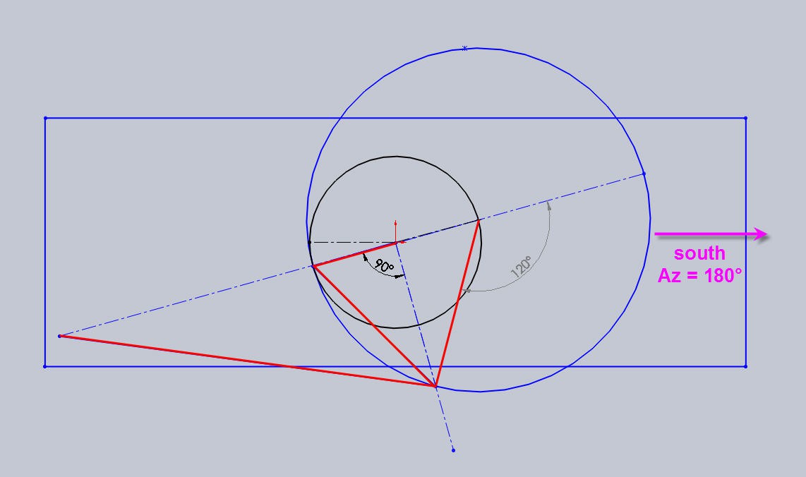
The rotation of the crank is directly proportional to the orientation of the panel. Let's fix one more degree of freedom. Assume that when alpha = 120°, lambda = 180° and we also have the panel pointing to the south.
That is Azimut Az= 180°.
![]()
We can now use Excel to look at the curves of motion.
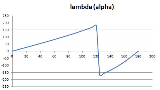
We have this curve when plotting lambda as a function of alpha
![]()
The discontinuity at 180° is normal and can be avoided by adding 360°
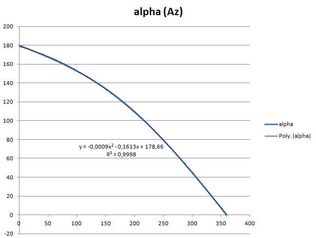
Thus we can plot the reverse curve alpha as a function of lambda and knowing that Az = 360 - lambda, we can get the curve alpha as a function of Az.
![]()
This curve is obviously non linear. It could be mathematically computed, but it can also be nicely aproximated by a degree 2 polynomium. And as I am lazy and Excel does this very well alone, we even get this equation!
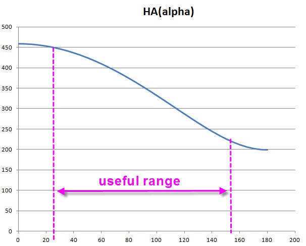
Finally we can also have a look at the motion of the linear actuator as a function of alpha.
We can see that when the two moving arms are too close the motion will be very inefficient. Useful range would be for alpha between 30 to 150° ("linear" portion of this curve).
![]()
Nevertheless, even with this "limited" range, our rotation (lambda) will be far above 180°. This was my target!
We will test all this after modification of the code to implement these equations into the firmware.
-
a new Azimut mechanics
09/25/2022 at 19:21 • 0 commentsAlthough the current system worked fine, I discovered that the Azimut axis was a little "weak"
- the worm gear has a limited accuracy : 1472 rotations for 180° of azimut motion
- the worm gear has a limited torque
Consequently it occured that in windy conditions the stepper motor stalled and thus missed pointing to the sun.
So I decided to try another design directly inspired from excavators where the bucket can rotate 180° with a linear actuator.
![]()
The reason why I went to this design is simply because I wanted to follow the sun all day long. Even in june when the Azimut rotation spans from 60° to 300°... That is 240° of azimut motion. A directly mounted linear actuator would allow only 150° of motion which would be far under my expectations...
And, of course, like a worm gear, I still wanted a leadscrew to allow to keep the position when the motor is idle.
Cinematics
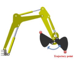
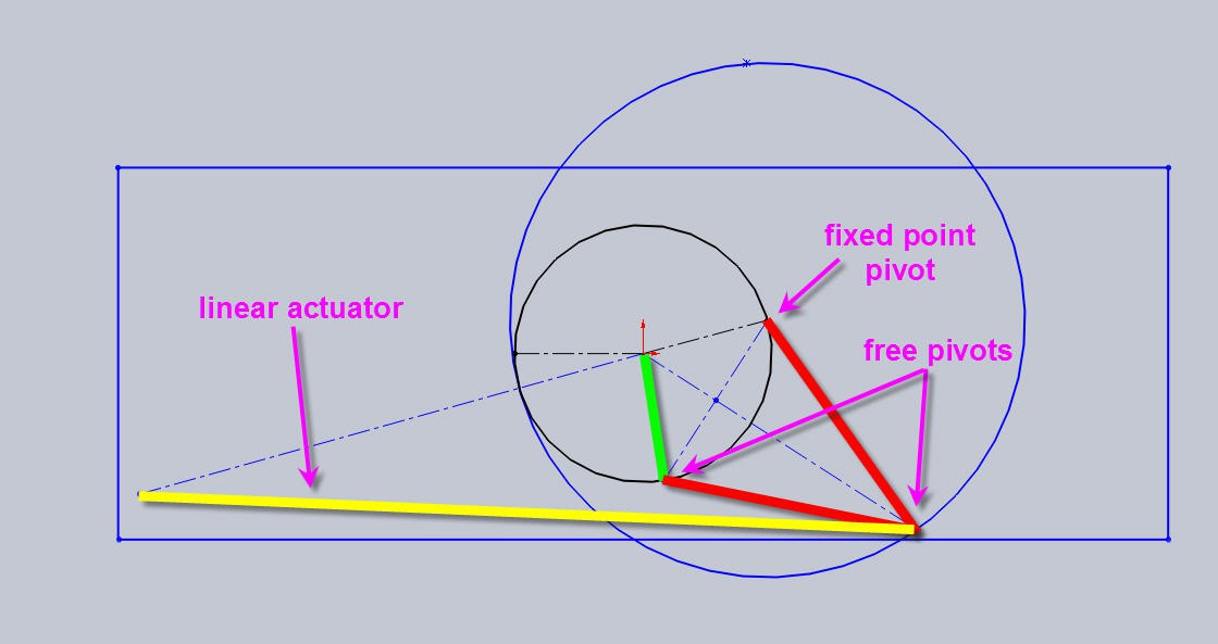
I made my own "bucket" and here is the principle of cinematics:
![]()
This drawing explains a little more how this cinematics works:
- yellow: linear actuator
- red: two arms
- green: a crank attached to the bottom plate
![]()
We can clearly see that more than 180° of Azimut rotation are accessible (theoretically). But we have to see what will be the "safe" range where torque on the crank will be enough to rotate the solar panel...
Building this cinematics
Once again I decided to build this new mechanics mostly with 3d printed parts (and with free plastic bottle PET filament)!
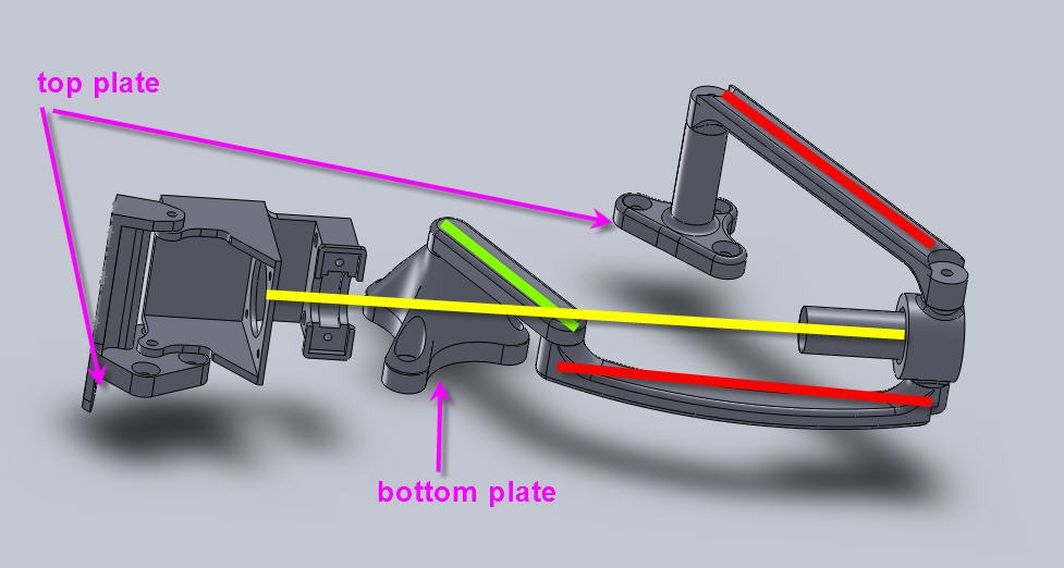
Here is the current design. With the same color legend, you can recognize the moving parts. Added in purple the "Z" information where the top and bottom plates are fixed.
![]()
All the stl files needed to this new Azimut mechanincs are available here.
You can also find them into my Thingiverse's pages
Mounting it on the Tracker
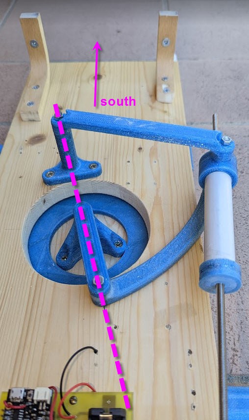
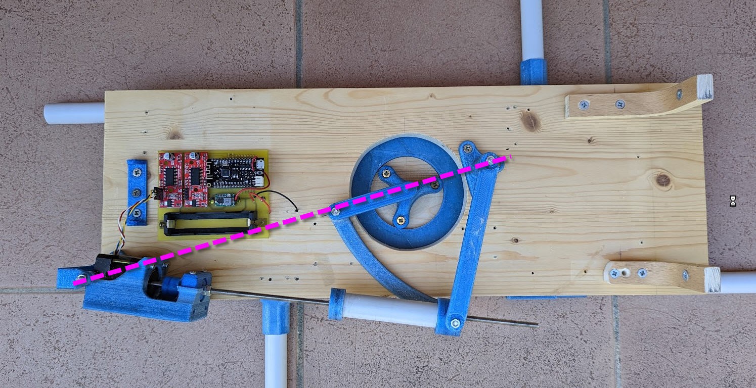
Mounting the parts on the Tracker is quite easy. The only important thing to keep in mind is alignment on the "X" axis.
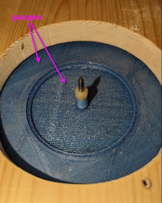
The crank must be properly centered on the bottom plate. Use the 3D printed gauges to help you find the center. Put a drill bit into this gauge to align this center with the linear actuator axis and the moving arm holder.
Draw this "X" axis line with a pencil and find the center of the moving arm holder, then fix it in place (length of one arm is 130mm and the distance between the lazy Suzan center and the moving arm center is also 130mm).
![]()
When this done, align the crank and fix it to the bottom plate. In this position the solar panel should point exactly to the south. We will see later why this is important!
Note that you can safely leave the gauge into the "lazy suzan" it will not rotate as lying on the fixed bottom plate.
![]()
![]()
Your new Azimut axis is now finished, the leadscrew should rotate freely by hand and should also rotate the top plate.
But how does it rotate ? What are the equations of motion ? This will be explained into the next log !
-
Publishing V2 of Solar Tracker firmware and Android companion App
09/17/2022 at 17:03 • 0 commentsAs promized, here is the source code for:
- The SolarTracker firmware : SolarTracker on my Github
- The Panel Orientation Android App : PanelOrientation on my Github
Don't forget to dowload the V2 of these files.
As usual, if you prefer to download the Apk it is here!
They work together and allow to ease the Solar Tracker Initialization
![]()
Full details into this log
-
Adding power storage
08/30/2022 at 16:36 • 0 commentsWhat would be a solar system without a battery ?
A power bank is especially helpful if you hope to use solar energy when there’s no sun: illuminating a campsite at nighttime, charging your phone when raining, or keeping your laptop running on a cloudy afternoon are all good examples.
However the price of a power pack can be as high as the rest of the system... Well unless we try to build one for free!
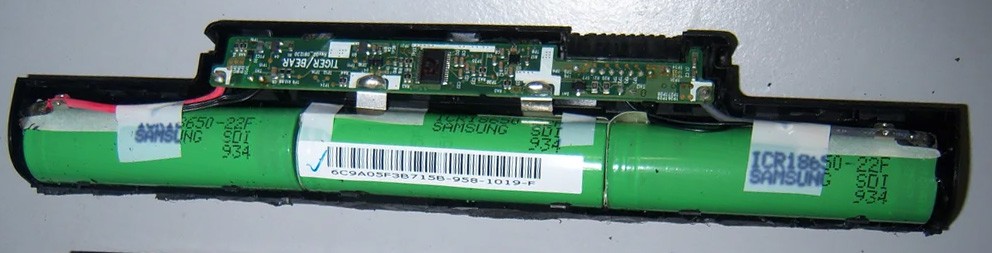
There are a lot of tutorials on internet to build 18650 lion cells packs. I decided to build one for my panel, reusing old cells scavaged from laptops packs.
Very often laptops packs die only because a few cells are dead. The Battery Management System shuts down the whole battery and you have to change it... But some of the cells are still into good condition.
This was the principle of "Reuse, Recycle Revamp" Challenge of Hackadays'Prize. So why not trying to keep this challenge's spirit and reuse laptop cells for our battery pack !
It will also have the advantage to stick to the Planet friendly challenge's objectives : "For this challenge, we want you to focus on minimizing the costs around building and installing clean energy solutions. This extends to the way energy is stored as well, to maximize the efficiency of the entire infrastructure."
Energy storage wasn't yet covered into my project, it will be done now!
Going back to our 18650 cells, we will have the delicate (and long) task to evaluate the health of each cell individualy. This is done by charging/decharging each cell and taking note of the capacity in mAh.
![]()
I succeeded in scavaging 3 laptops and finally got 12 "good" cells with almost the same capacity.
Then we have to design a pack...obviously coping with the number of cells we have got and the capacity of your panel.
My panel is given for a MPPT voltage of 16.1V, so I decided to build a 4s pack (4 cells in serie).
Why 4s ? as I can barely reach 4*4.2V = 16.8V with my panel (4.2V being the max voltage for a 18650 cell)... well simply because I do not plan to balance my pack every time I charge it... So a safety margin can be applied and charging the pack at 16V will be sufficient to keep it into good health even if a light unbalance is present!
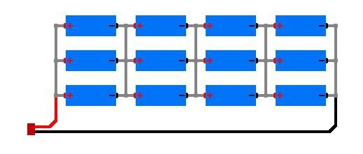
Having 12 cells my pack will thus be a 4s3p
![]()
The pack can be composed using the pack_builder tool proposed on repackR web site.
simply enter the capacity of each cell, and the site will tell you the best configuration and dispaly a nice summary
![]()
That's it ,
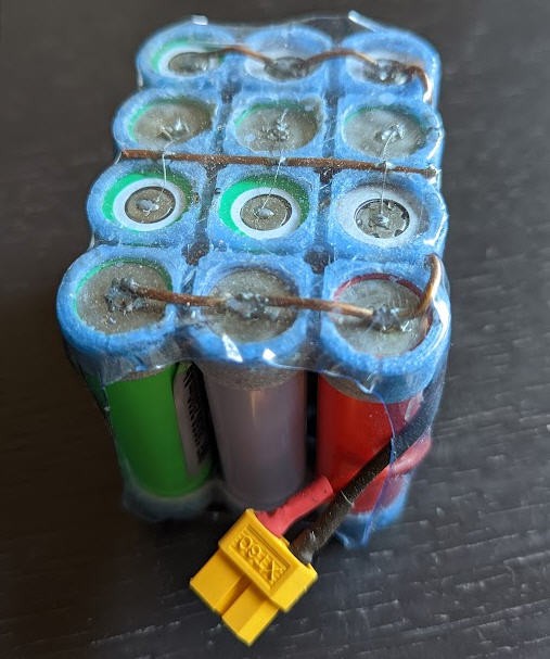
- print in PET the battery supports provided on my thingiverse account,
- install the bats,
- use 2mm copper wire as bus bars and solder the pack. I use thin wire as "fuse" to connect the cells to the bus bars. This is a safety protection to "fuse" these wires if too much current is drained from the cell.
- Be careful to avoid any short when soldering.
- Precharge all the cell at the exact same voltage before soldering
- Then add a balancer plug,
- Then use an old lipo pack connector for plus and minus.
- Then use another plastic bottle as heatsrink tube!
![]()
You are now ready to use the balance plug to balance your pack and charge it.
A few words of caution
This pack is in the range of 5000 mAh at 16V so can be "powerful enough" to be dangerous...
- the pack is not equiped with BMS.
- Avoid any overcharge (it would take fire...)
- Avoid any underdischarge (less than 12V) the pack would be totally dead...
I will use this pack on my solar system. I will balance the pack only from time to time.
I do not intend to drain high current from this pack (1A to 6A max).
As it sustains 5Ah you can charge it at 1C that is between 5 to 6A. This is perfect for the panel (100W at 12V --> 8A absolute max.. rather 4A in real life).
Once again be careful with these cells they can be very dangerous... this videos on youtube demonstrates the effect of overheathing a lion cell up to catching fire...
-
Equations of motion
08/30/2022 at 15:43 • 0 commentsThe "maths" of this project could be quite complex but clever people published the most difficult parts : sun equations
I do use two different codes to compute sun position but hopefully these codes give the same results !
- first one is into my Android "companion App". The heart on the computations can be found here : astro_library,
- second one is the arduino library solarCalculator which is running into the ESP32 firmware of the Solar Tracker.
Both do more or less the same job, they provide functions to calculate the times of sunrise, sunset, solar noon, twilight (dawn and dusk), Sun's apparent position in the sky, equation of time, etc.
I do only use the solar position at a given time and at a given position on the earth.
Knowing the Sun angles (elevation and azimut) we have now to "translate" them into "number of steps" to be applied to each stepper motor on the Solar Tracker.
Let's start by the simpler: azimut
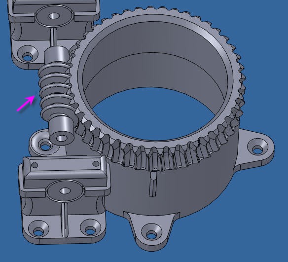
Azimut motor is directly driven by a vertical axis. One full rotation of the worm Gear induces a rotation of one tooth of the vertical gear.
![]()
the motion of the azimut motor is thus really simple :
stepsToMoveAz = ((currentAz - previousAz) * wormGearRatioAz * stepsPerTurnAz) / 360;        //it's an integer
    currentAz = previousAz + (float)stepsToMoveAz * 360. / (wormGearRatioAz * stepsPerTurnAz);  //so needs to recompute real Az value
three parameters are needed:
float wormGearRatioAz = 44.0;
int stepsPerTurnAz = 200;
#define SOLAR_PANEL_R 540   //expressed in mm
basically, the number of teeths of the azimut gear and the number of steps per turn for the stepper plus the panel width. Easy!
Now the elevation is a little more tricky
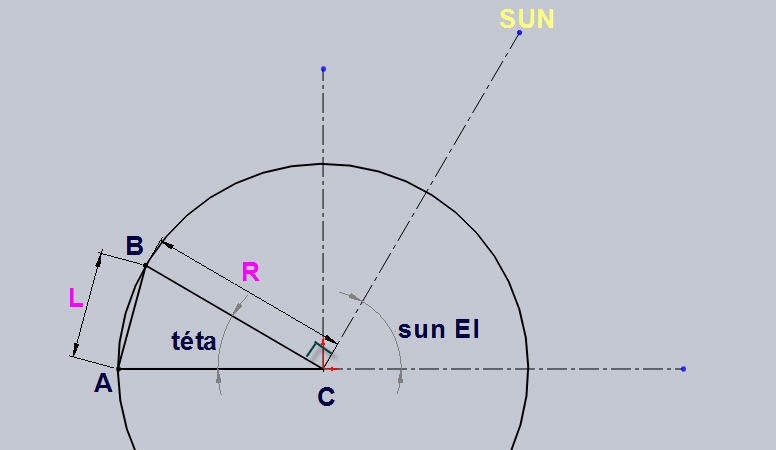
Elevation axis is actuated by the linear leadscrew. The motion is depicted on this drawing
![]()
where
- C is the center of motion (bottom long axis of the panel where are located the hinges)
- A is the top plate where is fixed the elevation stepper motor
- B is the top of the panel where is located the leadscrew hinge
The sun is on the top right corner and we want it to be perpendicular to the panel (BC)
- BC = R is thus the width of the panel
- A has for coordinates (R, 0)
- B has for coordinates (R.cos(téta), R.sin(téta)
we want to compute L = distance(A, B)
L^2 = (xB - xA)^2 + (yB - yA)^2
Thus
L = Sqrt((xB - xA)^2 + (yB - yA)^2)
L = Sqrt( (R.cos(téta) - R)^2 + (R.sin(téta) - 0)^2)
L = Sqrt( R^2.cos^2(téta) + R^2 -2.R^2cos(téta) +R^2;sin^2(téta))
L = Sqrt( 2.R^2 -2.R^2cos(téta))
and as cos(téta) = sin( Sun_El)
L = R. Sqrt(2 - 2.sin(sun_El))
This equation is directly implemented into the firmware
//length = R* sqrt(2 -2sin(sun_El))
    previousElLength = SOLAR_PANEL_R * sqrt(2 - 2 * sin(previousEl * pi / 180));
    currentElLength = SOLAR_PANEL_R * sqrt(2 - 2 * sin(currentEl * pi / 180));
This being done, we just have to convert the length into steps:
stepsToMoveEl = ((currentElLength - previousEl
Length) * wormGearRatioEl * stepsPerTurnEl) ;     //it's an integer
currentElLength = previousElLength + (float)stepsToMoveEl / (wormGearRatioEl * stepsPerTurnEl); //so needs to recompute real currentElLength value
currentEl = 180. / pi * asin(1. - pow(currentElLength / SOLAR_PANEL_R, 2) / 2.);
                 //and real El value
and we need two other paremeters for this:
float wormGearRatioEl = 1.0 / 0.8;                  //for M5 thread, 0.8mm per turn
int stepsPerTurnEl = 200;
If you build your own Solar Tracker with the same Azimut/Elevation axis you should only have to verify these formula and tune the parameters to your own setup.
-
A light market analysis
08/29/2022 at 18:43 • 0 commentsHaving a fully working solar panel system that I designed for less than 55 USD, I wondered if there was a business model for such a system.
The critical device is obviously the solar tracker as we can already find cheap MPPT controllers everywhere on internet !
I used google to search for MPPT controller 200W and got plenty of results for less than 100USD.
So, IMHO, trying to industrialize my MPPT controller would be a waste of time and money! We can keep my design as it is for hobbyists who really want something cheap and "Android controlled".
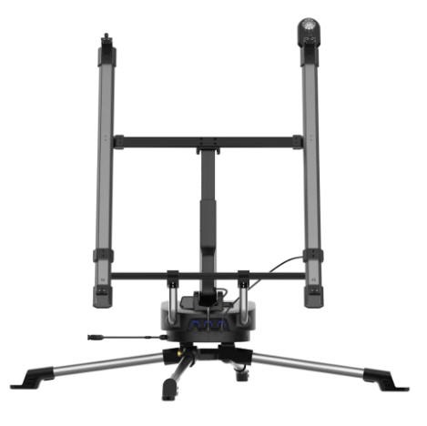
On the other hand searching for solar panel tracker mobile gives far less results and leads to very expensive systems.
For instance the best I found was the Ecoflow's solar tracker.
![]()
It is a very well designed system, very versatile but extremely expensive (3399$). IMHO, the return on invest for a buyer would last for decades... considering that you will gain 30% to 40% (in average) more power from your 100-200W panel ... See below for ROI evaluation.
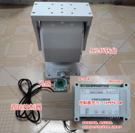
A few other solutions exist on the chineese market accessible via alibaba. Most of them are for "big panels" and not intended for mobile systems. I even found "kits" around 700$ on aliexpress
![]()
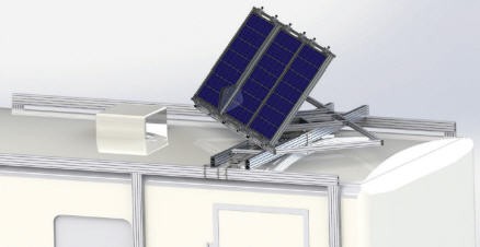
I found also a clever Mobile Solar Tracking System design but with no follow on for industrialization ...
![]()
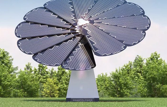
And I wouldn't finish this survey without mentionning the really beautiful concept proposed by SmartFlower
I want it !
![]()
But once again, the commercialization of this product by french electricity provider (EDF) was a failure... Product too expensive, mechanical parts fragile, not adapted to windy area... The story is not finished yet the Autrian company Smartflower still exists!
Industrializing my solar Tracker
My tracker has now almost 4 months of operation (of course not daily but regular). I know quite well its weaknesses and strengths. Some of the defects have been corrected during the prototype design phasis but a few other remain !
main cons
light weight: this is a real specification but can be considered has a drawback... This system cannot sustain high wind conditions, even if you fix the body legs into the ground...
We have to cope with this if we want a portable system... and a cheap system
waterproof: currently my electronics is not packaged into a waterproof case. It should be done for a commercial product. The panel must sustain rainny conditions.
main Pros
portable: the solar tracker is quite compact and very light. It is perfect to be put into a van and to be used everywhere in the fields.
easy to setup: using such a system should be easy. I mean, no complex tuning and fully automatic operations. Set it and forget it. My design allows to be deployed in less than 5 minutes. The companion App is handy to position the panel and to setup time and location into the tracker.
accurate: position should be fairly acurate. Tracking should work even in cloudy conditions. A no sensor system relying only on computations of solar position is a must.
low power consumption: the system should eat as less energy as possible. This is the case with my design where motors only draw current when in motion (~5s every 10 minutes).
failsafe: the system is automatic, it goes to morning position every night. It won't move if a low power is detected and resume operation when power will resume. It can connect to Wifi, Bluetooth, or rely on internal RTC clock. So it does not need internet to work although ntp time synchronization is possible and automatic if internet is available. In cloudy or shaded conditions the tracker will continue its job so that the panel is always pointing to the sun (when it is shinning !).
and last but not least
cheap: This is a key concern. Return On Invest (ROI) won't be achieved if the solar tracker costs too much money.
what is "too much" ?
Well, expect a 100W panel to cost around 150USD including cheap MPPT controller. Expect this system to produce 60W per day during 7 hours. Energy produced will be 60*7 = 420Wh per day.
Expect a solar tracker to increase this production by max 40%. You will get 168 Wh more per day.
Assume a price of energy at 20 cts per kWh. 168 Wh will give you a daily bonus of .168*20 = 3.36 cts... Which is not a lot!
- If the tracker costs 100$ you will need 100/0.0336 = 2976 days... more than 8 years before ROI.
- if the tracker costs 50$ you will need 4 years.
So YES price is a key factor when designing a solar tracker. The tracker should not cost more than 1/3 of the price of the solar panel system to have a ROI consistent with the ROI of the panel. (30% gain of power means 30% cheaper price to have the same ROI duration).
Industrializing my design would be rather complex to balance the industrialization costs... Target selling price should be in the range of 50 USD. for such a light 100W panel.
Moreover: Is there a market for small solar tracker ? Probably yes if the price is very very low. Increasing harvest of energy is great when place is small (van, campers...). Expensive systems seems to be discontinued (try to buy Ecoflow's solar tracker --> sold out)...
Electronics itself is cheap and should remain cheap, software is qualified and open. Most of the price will come from the mechanical parts and the motors.
Amazing coincidence
While writing this log, my project got popularity on this blog. I did enjoy most of the comments as they were inline with the content of this log!
I would like to put the stress on Bret's comment which I consider extremely relevant:
"A tracking system is intended to increase the output of whatever panel is used and the design is NOT limited to just that one size of panel, it can be adapted to ANY size panel or array ! So once a system is working, take that design and mod it to work to move whatever array you wish to move.
/.../ It puts the output at near peak as long as possible, instead of 5 hrs. it moves to 9 average which is almost double, in some place it can be longer, like 10 to 12 or even 15. Plus it requires less material and space as far as the solar system not counting the tracking system."
So yes my design was intented to move my small and cheap panel and to apply MPPT to charge my bats. This design is at the very minimal cost you can imagine, but with known limitations...
If you scale up to a bigger panel, you will have to improve the mechanics, the motors, the actuators... while keeping this equation in mind : solar tracker price shouldn't be more than 1/3 .(panel + controller) .
But in any case, the software and electronics can be fully reused. Everything is Open source and Open hardware. Take benefit of this, read the code, update it to your needs. It should be simple!
And don't forget that the licencing model allows you to do what you want (use, modify, distribute) provided that you go on distributing the (modified) source code together with the system using it.
Low cost solar panel solution (MPPT + sun tracker)
portable flexible panel + MPPT controller + solar tracker system less than 55 USD ????