-
First Pico 2 Testing
08/29/2024 at 12:21 • 0 commentsJust tested the new Pico 2 and the results are pretty amazing actually.
The DNL issues, are obviously gone and with it the `cps correction` setting and some of the code in the event interrupt that had to handle the 4 error channels. Finally no more random peaks or missing channels in the spectrum!
Due to this combined with the more powerful processor cores (and FPU), the total dead time reduced significantly, which is probably the biggest change. With the same settings both on the Pico 1 and Pico 2 at default settings the dead time in energy mode halved (!) from ~24µs to ~12µs. The dead time in Geiger mode actually reduced more than that, it only registered ~1µs of dead time on the Pico 2, while the Pico 1 had about 4µs. This is of course only the software-measured dead time, there will still be a bit of a constant overhead on top of all of that, that cannot be measured in software. It's pretty safe to assume that this hasn't changed too much between the revisions, so the relative decrease in dead time is very significant.
The flash size is now triple that of the old version at 3 MB reserved for custom spectrum storage. This means you're able to record almost 3x the amount of spectra before running out of space, which is also huge.
The cherry on top of all of this is that power efficiency went up too. Without any further changes, the detector now consumes a good 10% less power than before according to my testing. I will also investigate the new sleep/dormant modes of the RP2350 as soon as there is support for these.
On a side note, I was able to overclock the Pico 2 to 250 MHz at the default 1V core voltage in the sketch, which is 25 MHz higher than with the Pico 2 (225 MHz). Therefore the `overclock` uf2 file will be clocked at 250 MHz from now on.
All of the hardware and software files are up to date now for the Pico 2 and development will continue on the Pico 2 from now on. The new board revision 4.2 is unchanged from the old one besides the switch to the Pico 2 and an updated BOM position for the out-of-stock buzzer. I will update the post on my website to also reflect these results.
-
OpenDosimeter Project
08/21/2024 at 10:09 • 0 commentsHey there, I wanted to give a quick shout-out to an awesome new derivative project: The OpenDosimeter.
If you're interested in dosimetry and radiation protection, go check them out! They're fully open-source and currently working hard to publish all the info and details needed to reproduce the device.
https://github.com/OpenDosimeter/OpenDosimeter


-
Raspberry Pi Pico 2 and the Open Gamma Detector
08/10/2024 at 18:03 • 0 commentsThis article was originally posted on my homepage.
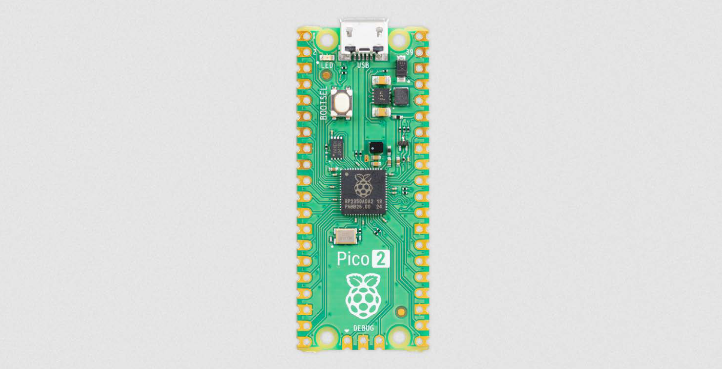
The RP2040 microcontroller that is being used in the original Raspberry Pi Pico finally got a worthy successor: the RP2350! And with it Raspberry Pi released a new and improved version of the Pico, fittingly named the Raspberry Pi Pico 2. This is a big change for the Open Gamma Detector project, because it is going to substantially improve device speed and analog readout.

The Raspberry Pi Pico 2, sourced from their Pico 2 product brief, see below.
It's a drop-in replacement part for the original Pico, which means the pinout and sizing is the same as well as the software should be compatible with any changes, which is actually pretty huge. Ideally, the original Arduino IDE sketch can be reused without any modifications and the used pins on the device also remain the same.
The new RP2350 boasts double the SRAM (520 KB), double the onboard flash (4 MB) and more powerful ARM Cortex-M33 cores. With it finally comes an FPU for faster floating point calculations and they actually fixed the DNL issues with the ADC boosting its performance by 0.5 ENOB! That means I can finally drop all of the botched code for the DNL issue compensation.
The chip also adds a ton of new security features and optional RISC-V cores, which is very exciting to see, but not really relevant for the project. However, this is going to make the Pico 2 and RP2350 hugely more popular for all kinds of different IOT projects as soon as a wireless version comes out.
What I'm excited to see as well is how the power draw changes for the whole device and if the switching regulator on the board changed, which could affect the noise levels on the board and most importantly, the noise at the ADC voltage reference. As far as I'm aware they also changed sleep and dormant modes, which should make them a lot more useful and more low-power compared to before. Anyways, the new core architecture will definitely change power draw, I'm sure. Let's hope it's for the better :D
I have pre-ordered a Pico 2 now and I'm going to have a look at it as soon as it arrives. I'm certain it'll be a substantial upgrade in all of the relevant aspects to the project. I'll keep you updated!
Check out the product brief from Raspberry Pi (PDF): https://datasheets.raspberrypi.com/pico/pico-2-product-brief.pdf
Let me know what you think and how this is going to affect all kinds of different projects!
-
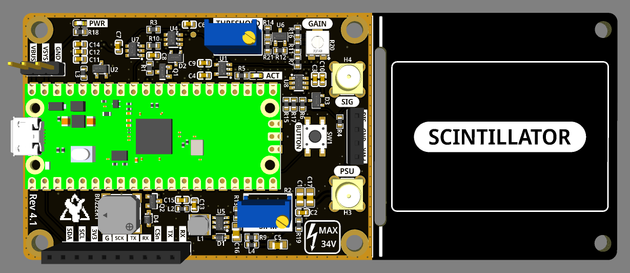
Rev 4.1: PCB Layout Update
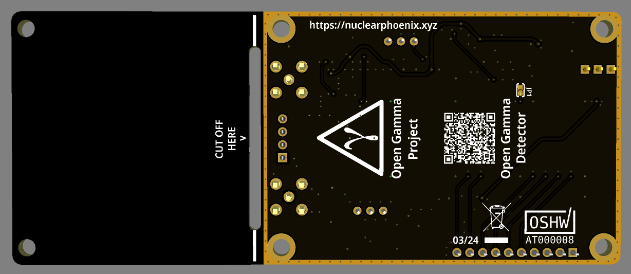
03/29/2024 at 12:00 • 0 commentsDid some work on the PCB and slightly updated the layout to make it all look better. The MCX connectors are now placed symmetrically on the board and the silk screen has had a heavy rework. On top of that I also added a grounded guard ring around the perimeter of the electronics section.
The only other change is a different type of 22µF cap for bypassing, which now has an increased max voltage rating to better cope with DC bias. Other than that, everything remains the same.


-
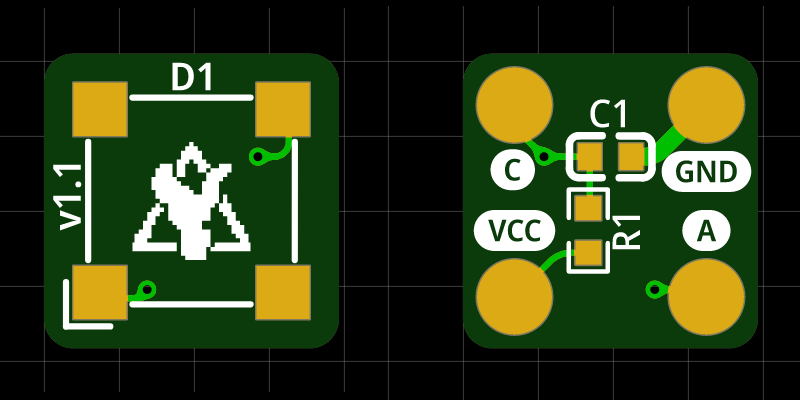
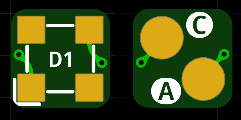
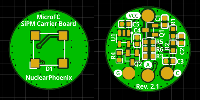
Updated SiPM Carrier Boards
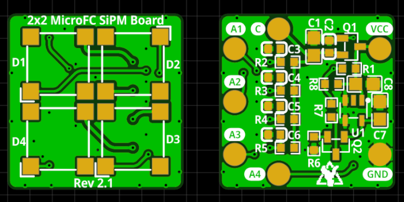
02/16/2024 at 20:38 • 0 commentsI reworked the SiPM carrier boards a little in terms of the layout and also used the opportunity to make a board for the 3mm MicroFC SiPM from onsemi. This will definitely come in handy if someone wants to play around with these little LYSO sticks (4x4x20mm or so). The files for the 3mm carrier board can be found on GitHub: https://github.com/OpenGammaProject/Tiny-3mm-MicroFC-Carrier-Board
At 6x6mm, the board is slightly larger than a 4x4mm LYSO scintillator face, but it really couldn't be much smaller and it should work reasonably well regardless.
Overall, the layout of all boards is now tidier and, above all, the important connections are all a lot more clear better marked. I also reduced the distance between the individual SiPMs a little in the 2x2 array. The circuit is otherwise identical.
Here are the latest PCBs:


-
FW 4.2.0: Recording to flash
01/20/2024 at 18:36 • 0 commentsThis new update is a little bit bigger than the last one. One major new feature is the option to record spectra 100% locally on the device and save the data to the onboard flash to be retrieved at a later point. You can start a recording via the serial interface and then keep track of the status or stop it manually before it finishes. The data that has been gathered can be again printed to the serial interface at any point after that. For this I have also added a couple new commands relating to the filesystem on the Pico's 2MB flash.
Because of these changes, your current settings and also the runtime stats of your device will be reset once you update! So be sure to note your settings beforehand and restore after the update if you changed anything.
There are also some smaller changes like a change in default settings (see below) and better formatting for the general info and fs info screens over the serial interface.
Full list of changes:
- Flash space (total 2MB) on the Pico is now divided 50:50 between the onboard file system and the program space (1MB for the filesystem). This change will result in a reformat of existing devices.
- Changed default settings for "subtract_baseline" and "cps_correction":
- subtract_baseline = true
- cps_correction = false
- Improved formatting of "read info" and "read fs" info screens. Also removed some irrelevant data from the "read fs" screen.
- Standalone recordings: Start and stop spectrum recordings via the serial interface, the rest will be handled by the device, you don't need an active connection in between and you can collect the data anytime after it finishes. The data will be saved to flash in a compatible JSON (NPESv2) format for viewing in other software. There is also a tiny indicator on the OLED for when the device is currently recording. The device will stop recording after the set time has run out and will autosave regularly (every 15 minutes) just in case of a power failure. New serial commands, pretty self-explanatory:
- record start <time in minutes> <filename>
- record stop
- record status
- New filesystem commands to view the contents of the data directory and of files that were previously recorded (NPESv2 JSON). There is also an additional command to remove files once you don't need the data anymore. The 1MB of flash on the Pico FS can hold a lot of spectrum files (get used and free sizes using "read fs" command). Commands:
- read dir
- read file <filename>
- remove file <filename>
I think these are really cool changes and finally start to show the power of this device. Neither do you need a sound card or any additional hardware to generate spectra, you don't even need a computer all the time anymore with the stock firmware. Set and forget. Set up your serial recording, and then come back hours later to "download" the data from the device. Just copy paste the contents into a file on your system and open it in Gamma MCA or a compatible program to view in all its glory. No additional computing needed. Doesn't matter what you do with your computer. Just be sure to keep the device powered ;)Enjoy!
-
FW 4.1.0: Button Changes
01/17/2024 at 22:31 • 0 commentsWith the latest firmware update I changed the way the buttons on the board work. In the past the BOOTSEL button on the Pico would always change the mode of the detector while the other button on the main board toggled the buzzer. This was always a bit odd to use honestly, especially when you have an OLED installed directly on the pin header next to the button.
With firmware version 4.1.0 the large button on the main board now took over the BOOTSEL button's job and changes the mode as well. BOOTSEL on the Pico will from now on always reboot the device into bootloader mode for easier updating. You can change the mode by pressing shortly on the other more accesible and larger button. Long-pressing on the button will toggle the buzzer on or off.
Also the display now reacts more quickly to reflect the change in mode by changing the screen after you pressed the button.
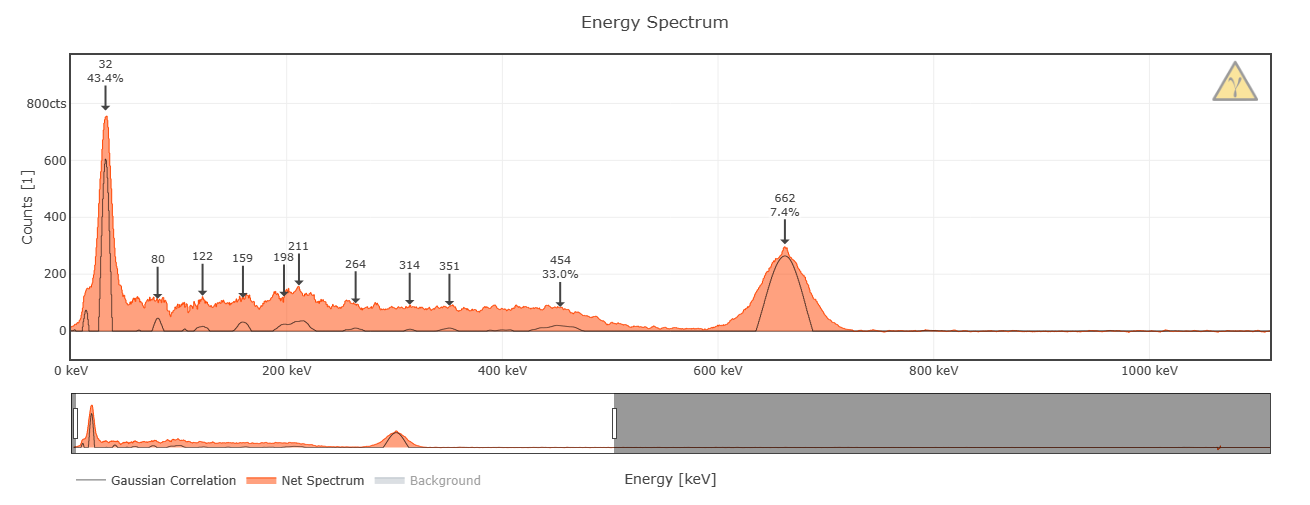
And last but not least, today I managed to break my record for my personal best achieved energy resolution. I used the same mushroom sample (Cs-137) that I always used before and got 7.4% @ 662keV, nice!

This is the configuration I used: 1x1" with 2x2 SiPMs like previously, but with a new detector main board.

It's actually one of the pre-assembled boards, which interestingly slightly outperformed my hand-soldered version by almost half a percent lol
Cheers!
-
Board Restock Rev 4
01/14/2024 at 00:01 • 0 commentsFinally, after all the delays, the long awaited restock is here. You can once again get the fully pre-assembled main boards for the Open Gamma Detector on Tindie. EDIT: It's the new version of course, Rev 4! Here's a link to the listing:
https://www.tindie.com/products/28827/
This time they come in a nice black color with ENIG surface finish and all the necessary connectors pre-assembled too. As always you will have to get yourself a SiPM and scintillator as these are not included. The boards will need to be programmed at the first start as they don't come pre-loaded. If you're not sure how to do this, here is a quick guide (it's really easy): https://github.com/OpenGammaProject/Open-Gamma-Detector/tree/main/software#firmware-files
Cheers!
-
(Small) Update
12/27/2023 at 21:29 • 0 commentsJust a quick reminder that the project is not dead (and also a very tiny update) :D
Regarding the Tindie restock, I'm sorry for the seemingly endless delays. The boards are currently in production and I'm expecting them to be in stock again ready for shipping by early to mid January.
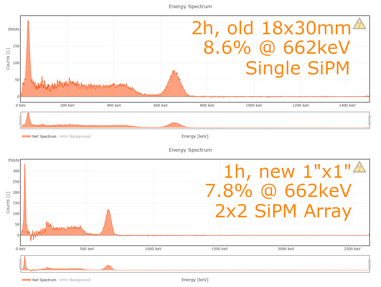
To keep you interested and as a sort of small additional teaser, here is a comparison between my "old" scintillator with only a single SiPM that I used for all spectra up to this day and a brand-new 1x1" crystal with the 2x2 SiPM array:

As you can see, the spectrum is a lot cleaner in total, the range is larger and the energy resolution is a lot better too. Keep in mind however, that this version costs at least around 100$ more than the "simpler" version, due to the added SiPMs and the larger, 4-layer array PCB.
The larger scintillator comes with some additional benefits such as greater efficiency and therefore also higher count rate. You don't need one as large as this, though. 18x30mm is also a great size already pretty capable.
-
Notes about averaging (settings)
12/06/2023 at 21:41 • 2 commentsI'm doing some last in-depth testing to optimize all the device settings for the best energy resolution possible and it looks like I found a much better suited setting for the ADC "averaging". In my case, I was able to get an improvement of about 1% just by switching this setting ("set averaging 2" from the default value 5). I've also just now changed the default value for averaging to 2 in the 4.x.x firmware to apply this improvement. If you already changed something in the settings, or you're using one of the older board revisions, you'll have to edit it manually.
Give it a try, it might even work on older board revisions, but your mileage may vary. Nothing can break, so just feel free to experiment. If you're not sure, just reset the settings afterwards and you're fine.

All-In-One Gamma-Ray Spectrometer
More sensitive to gamma radiation than a Geiger counter with the added bonus of telling exactly what's inside your samples!
 NuclearPhoenix