-
Battery Sizing
06/30/2022 at 18:21 • 0 comments![]()
![]()
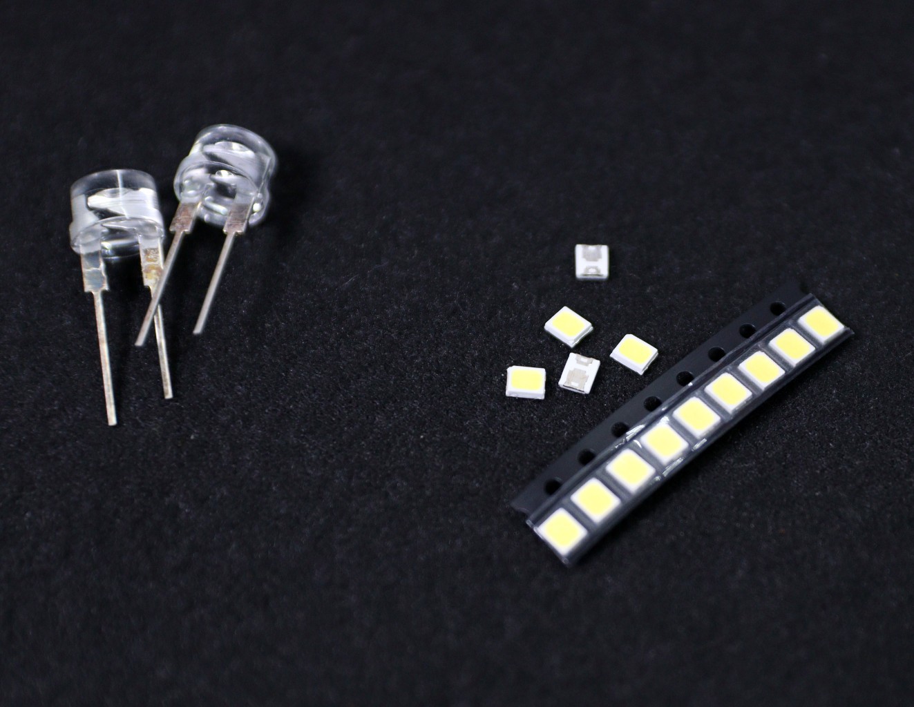
Earlier I used a 0.5W straw hat LED, but it is not so efficient and the lumens/watt is around 70-80.
So I am planning to replace the LED with a 0.5 Watt cool white SMD LED ( 2835 package). As per the SMD LED datasheet, the forward voltage (Vf) is 3.2V and the luminance is 150 lumens per watt.
My target lumens for the different modes of operation are as follows:
1. Mode-1 ( Low Brightness ): 15 Lumens with a backup time of 24hrs
2. Mode-2 ( Medium Brightness ): 30 Lumens with a backup time of 10 hrs
3. Mode - 3 ( High Brightness): 70 Lumens with a backup time of 5hrs
The power required to drive for the above modes is as follows:
1. Mode-1: 15/150 = 0.1W
2. Mode-2: 30/150 = 0.2W
3. Mode-3: 70/150 = 0.467W
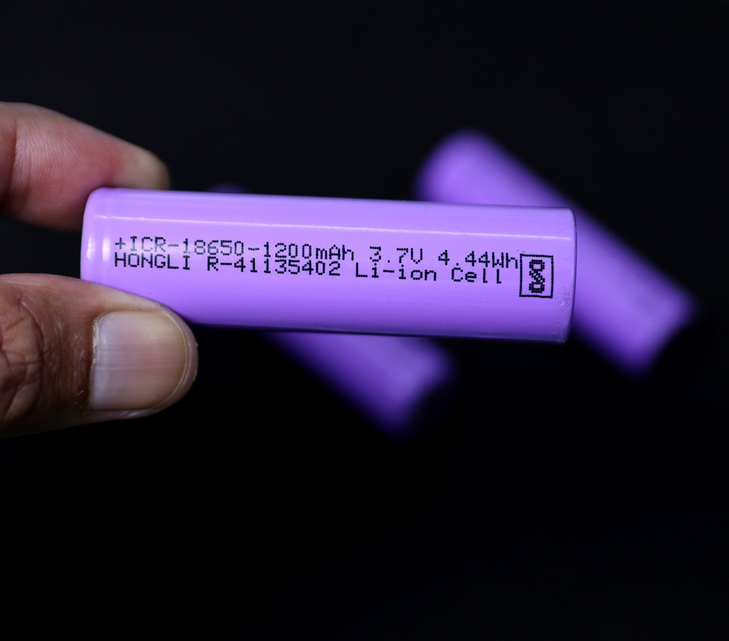
In the following table, calculations are presented to estimate the battery capacity. I have considered a 18650 Li-Ion battery (3.7V) with 80% DOD.
Mode Power (W) Current (mA) Energy ( Wh) Driver Efficiency Updated Wh Capacity (mAh) Battery DOD Final Capacity (mAh) 3 0.467 145.9 2.335 85% 2.75 742.4 80% 928.1 2 0.2 62.5 2 85% 2.35 635.9 80% 794.9 1 0.1 31.3 2 85% 2.35 635.9 80% 794.9 Formula Used in the above table:
1. LED Current (mA) = Power (W )/ LED Voltage (3.2V)
2. Energy (Wh) = Power (W) x Backup Time (Hrs)
3. Updated Wh = Wh/ Efficiency
4. Capacity (mAh ) = Updated Wh / Battery Voltage ( 3.7V )
5. Final Capacity = Capacity / Battery DOD
From the above table, the maximum charge required for the battery is 928.1 mAh. However considering the market availability and taking some additional margin for sunny days, the final battery size selected is 1200 mAh.
-
Installed the Components in the V2.0 Enclosure
05/11/2022 at 18:46 • 0 comments![]()
![]()
![]()
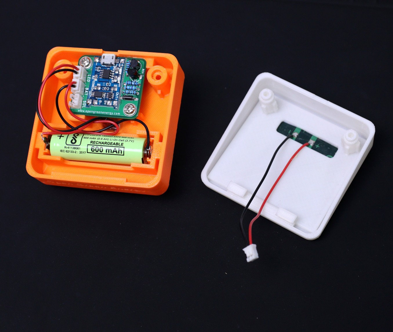
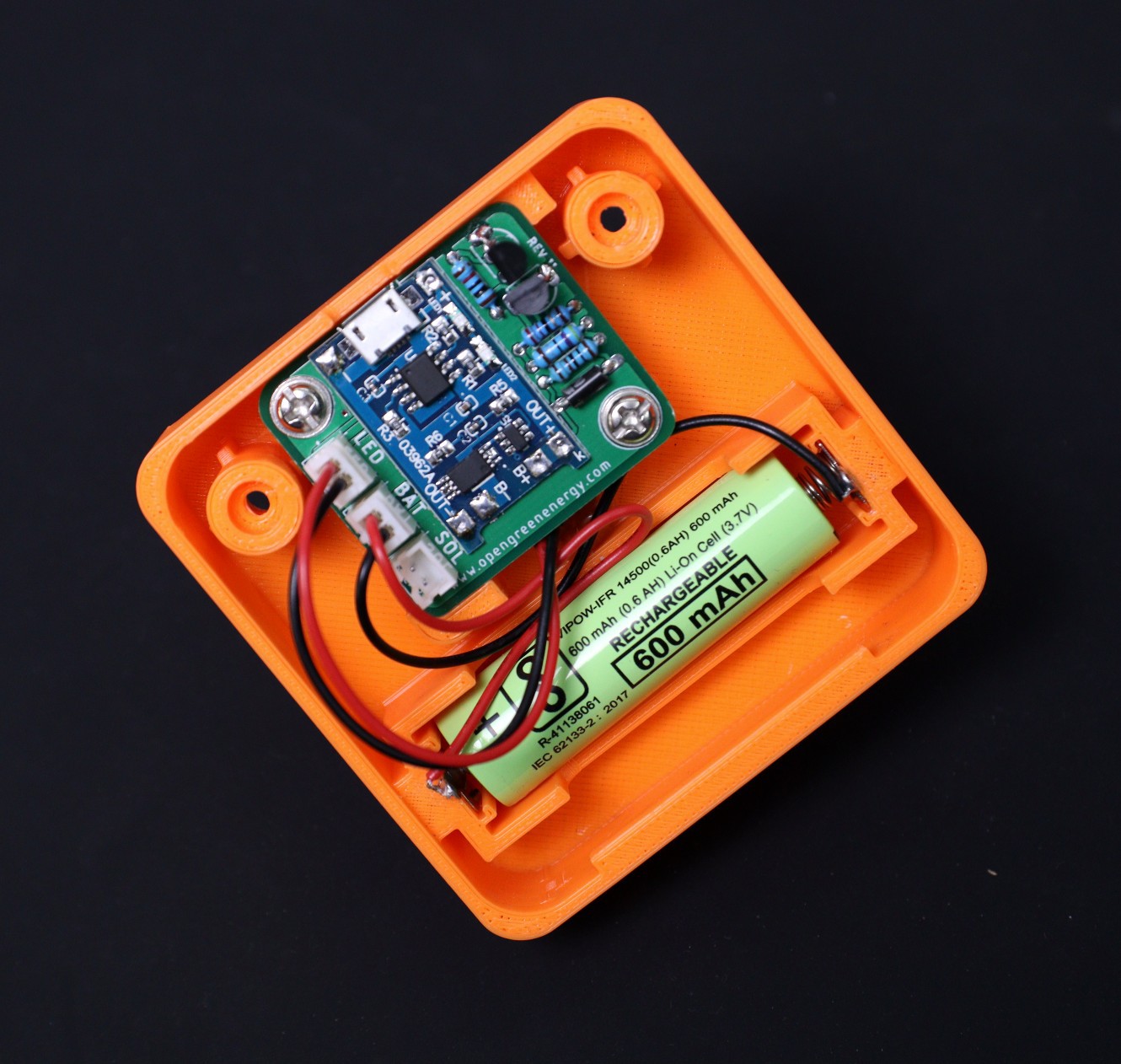
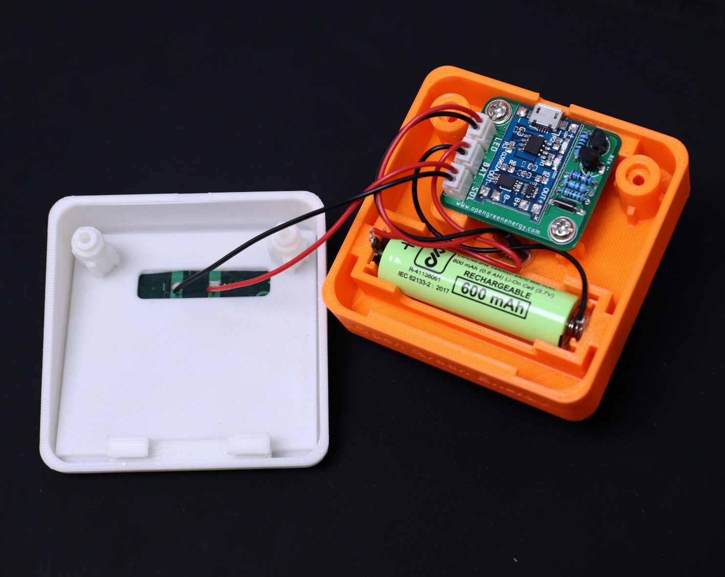
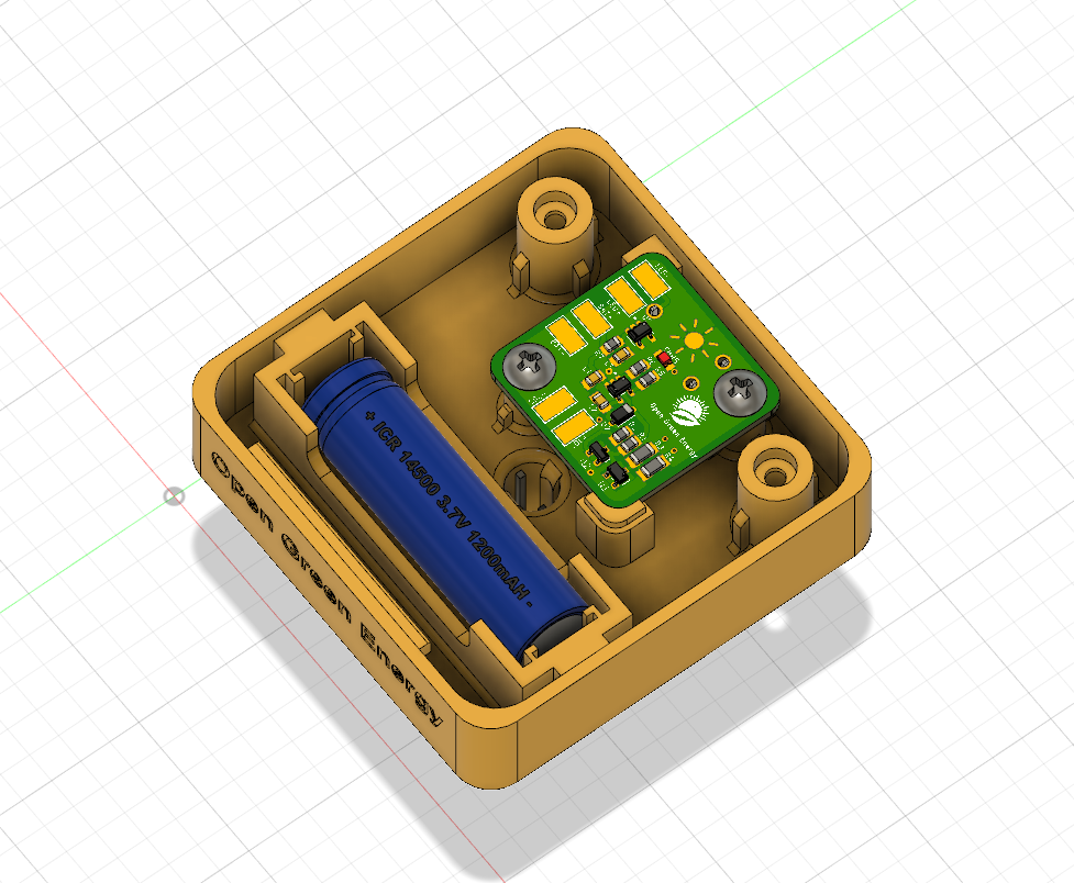
Installed the PCB and all other external components as I have done in my earlier version. One change is that instead of directly soldering the terminal wires to the PCB, I have used JST PH2.0 connectors.
It will be easier for users and the connection is far better than the direct soldering. There will be no chance of short circuits and loose connections.
-
Printed the Enclosure for STEM Education PCB
05/11/2022 at 18:35 • 0 comments![]()
![]()
![]()
![]()
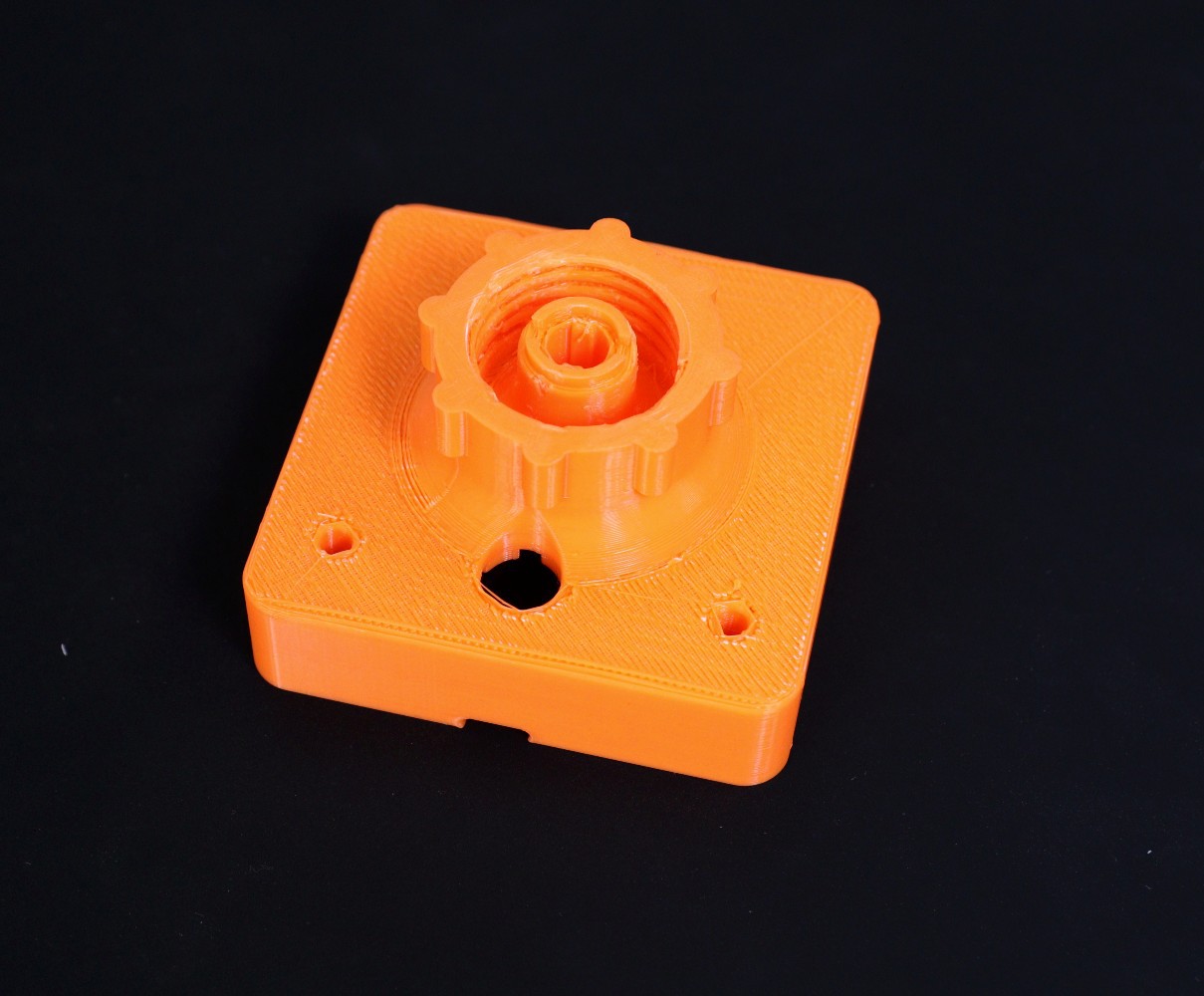
I have printed the modified enclosure for STEM education PCB. I have printed the two parts of the enclosure using filament in two different colors. The outcome is really nice and all the components fit as intended. The dual color enclosure is looking more beautiful than the single color one.
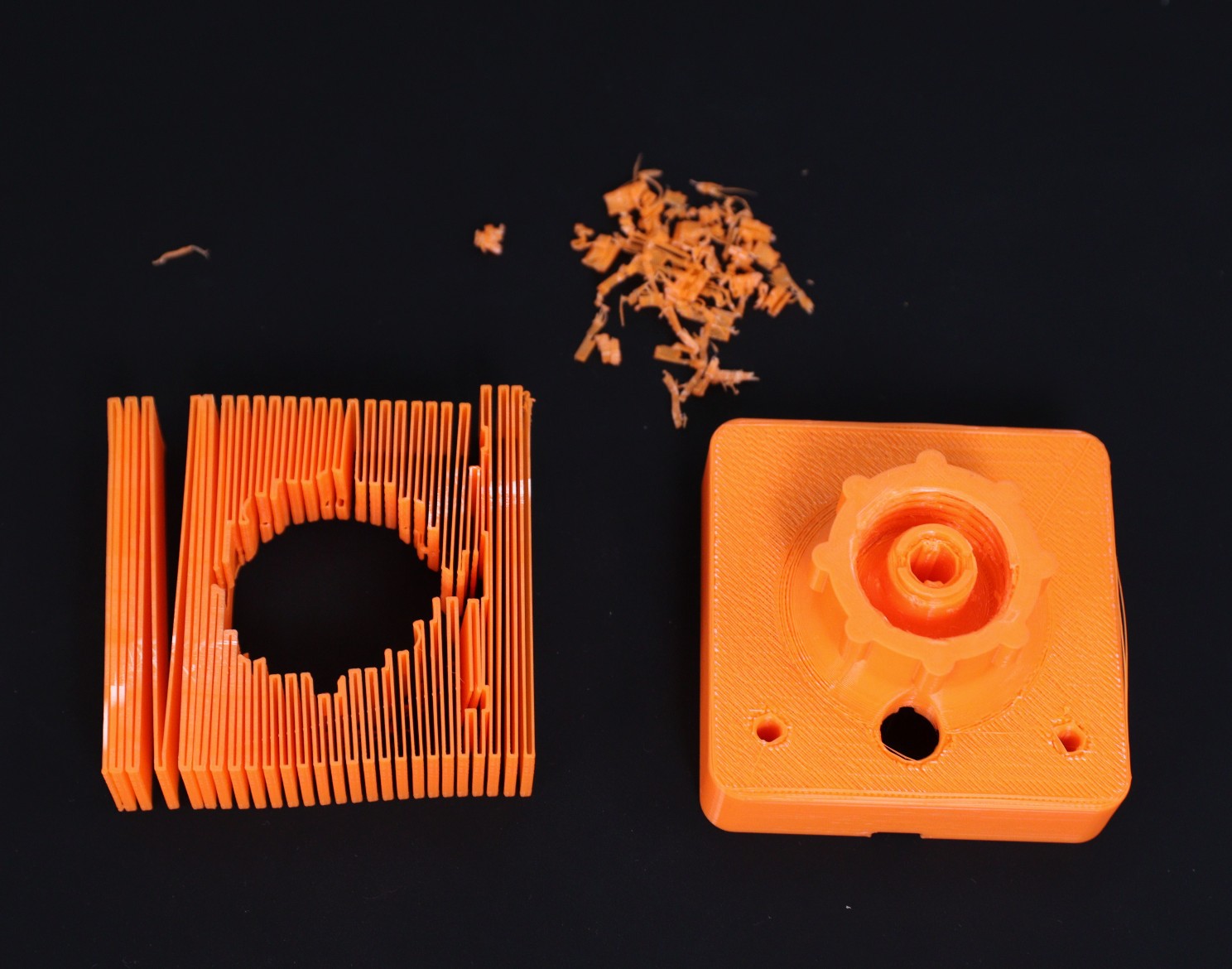
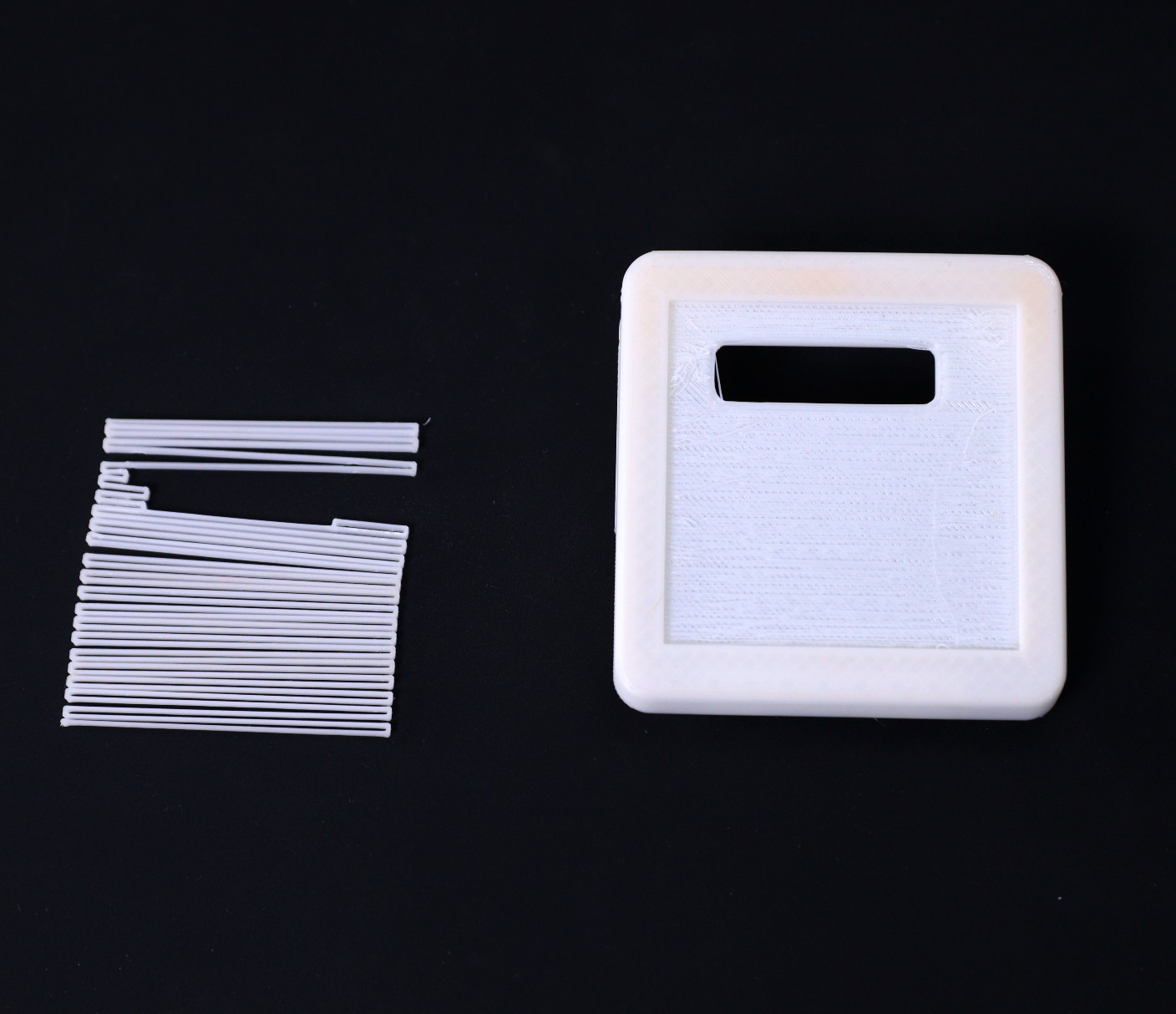
I am planning to modify the design so that it can be printed without support. Stay tuned for the next update.
-
Designed a separate Enclosure ( V2.0 ) for STEM Education PCB
05/09/2022 at 08:30 • 0 comments![]()
![]()
![]()
Designed a dedicated enclosure to fit the new PCB for STEM education.
The enclosure has 5 parts:
1. Main Body
2. Top Cover
3. LED Holder
4. Diffuser
5. Button
The Main Body is basically designed to fit all the components including the battery. The top cover is to cover up the main body and mount the solar panel on it. The LED holder is used to hold the LED and the diffuser is used to diffuse the LED light in all directions. The button is used to operate the switch on the PCB from outside.
Download the .STL files from Thingiverse.
You need a support structure for printing the main body and top cover. You can print the enclosure parts either in PLA, ABS, or PTEG filament.
I am trying to modify the design so that it can be printed without support.
-
PCB for STEM Education
05/09/2022 at 03:57 • 1 comment![]()
![]()
![]()
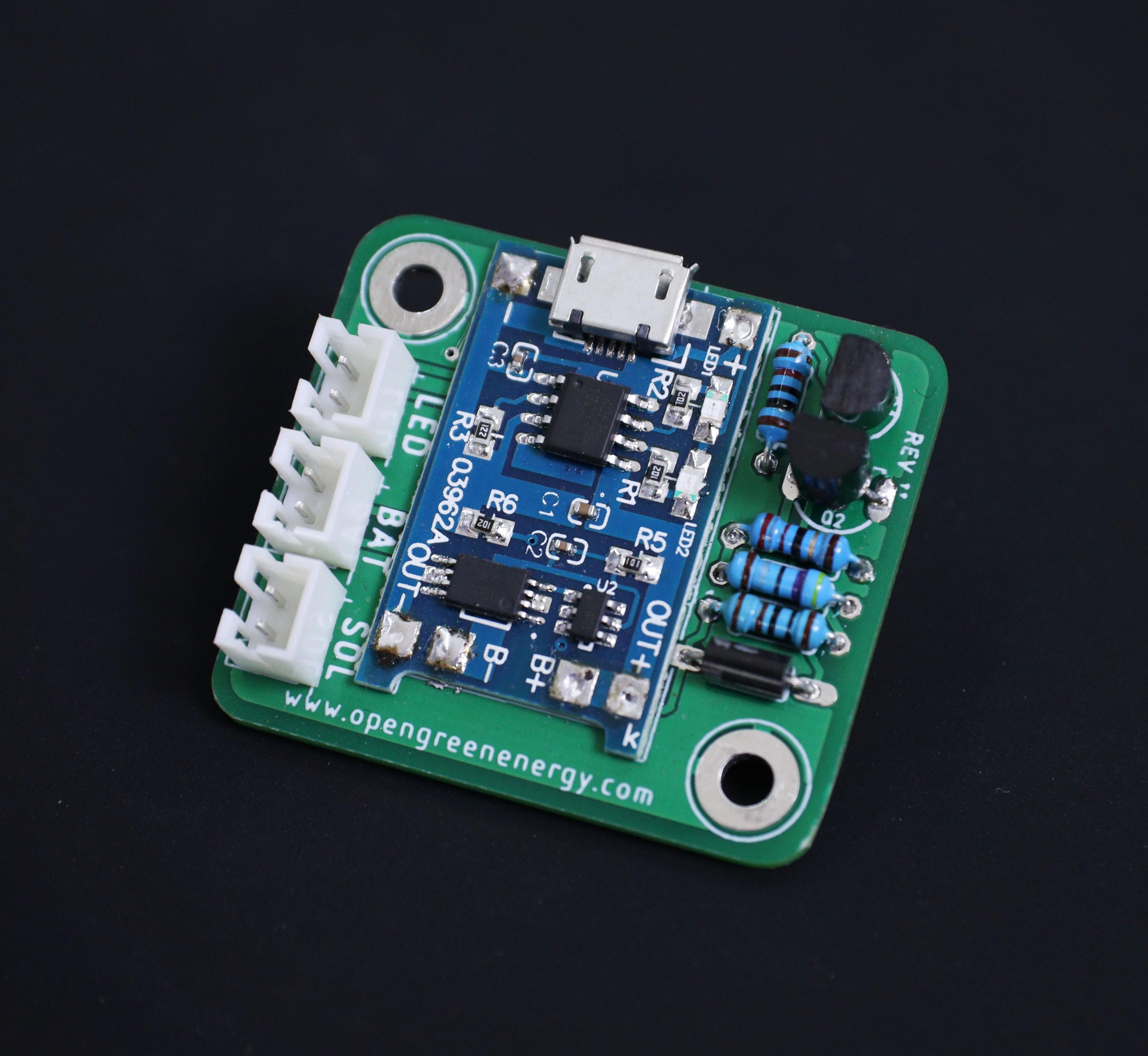
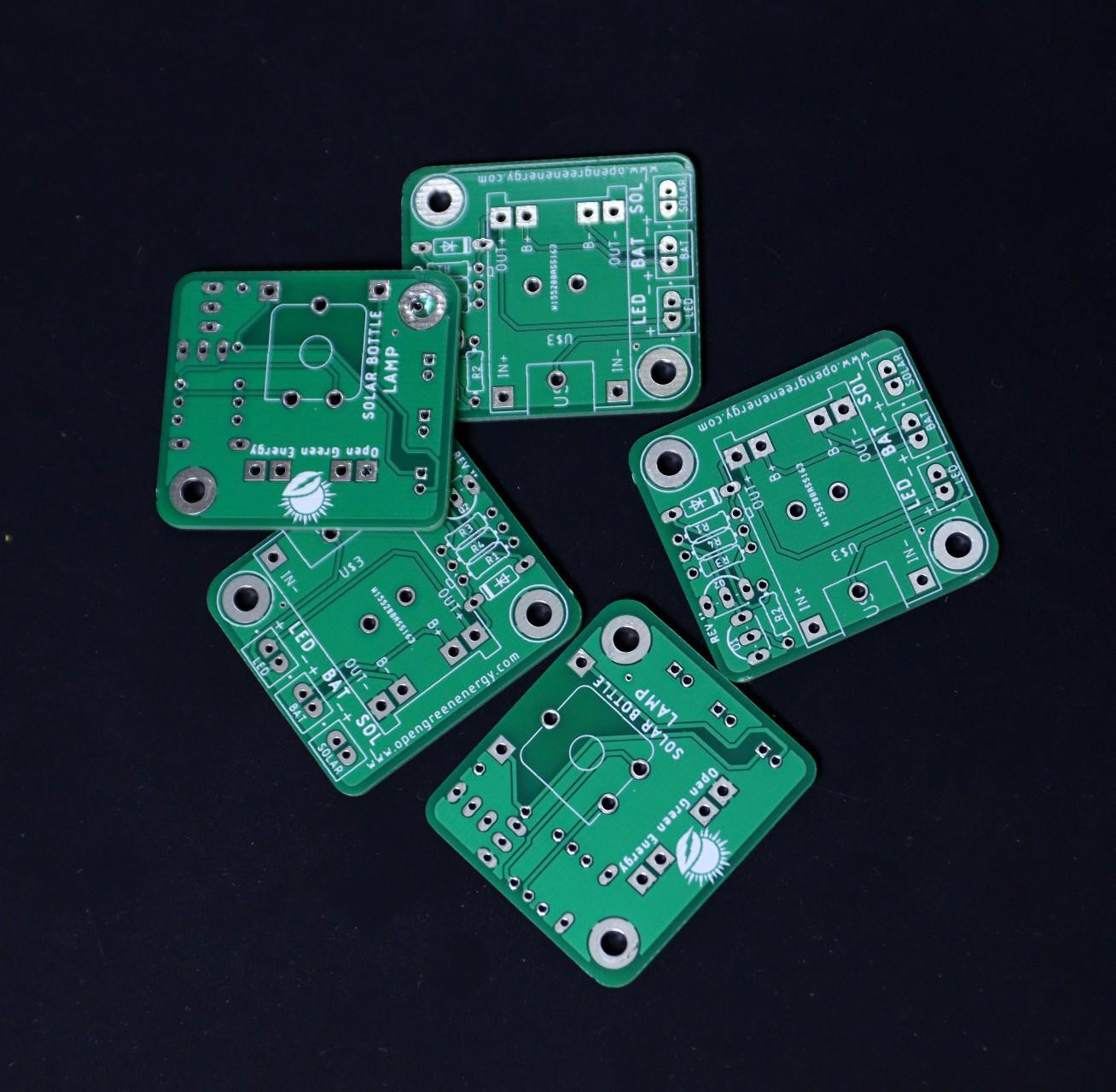
The PCB board used in the earlier version was made of all SMD components as result users who don't have SMD soldering experience can't take advantage. So I thought to redesign the PCB by using all through-hole components so that anyone can make it.
This board can easily be assembled by school children which can be used for STEM education in the school. By making this project they will aware of the sustainability and use of renewable energy.
Now the kit is available on Tindie
-
First Field Test
05/03/2022 at 04:07 • 0 comments![]()
![]()
![]()
![]()
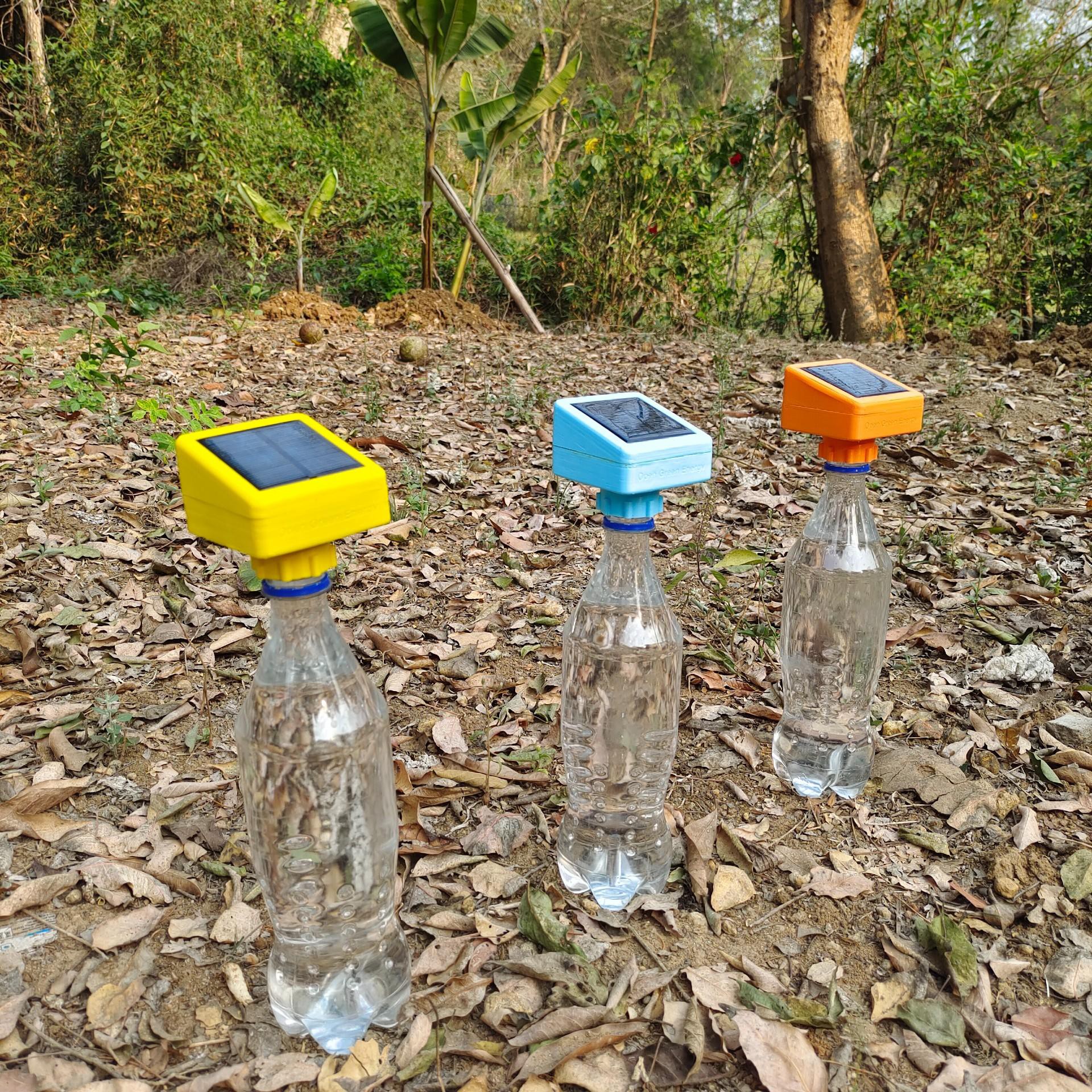
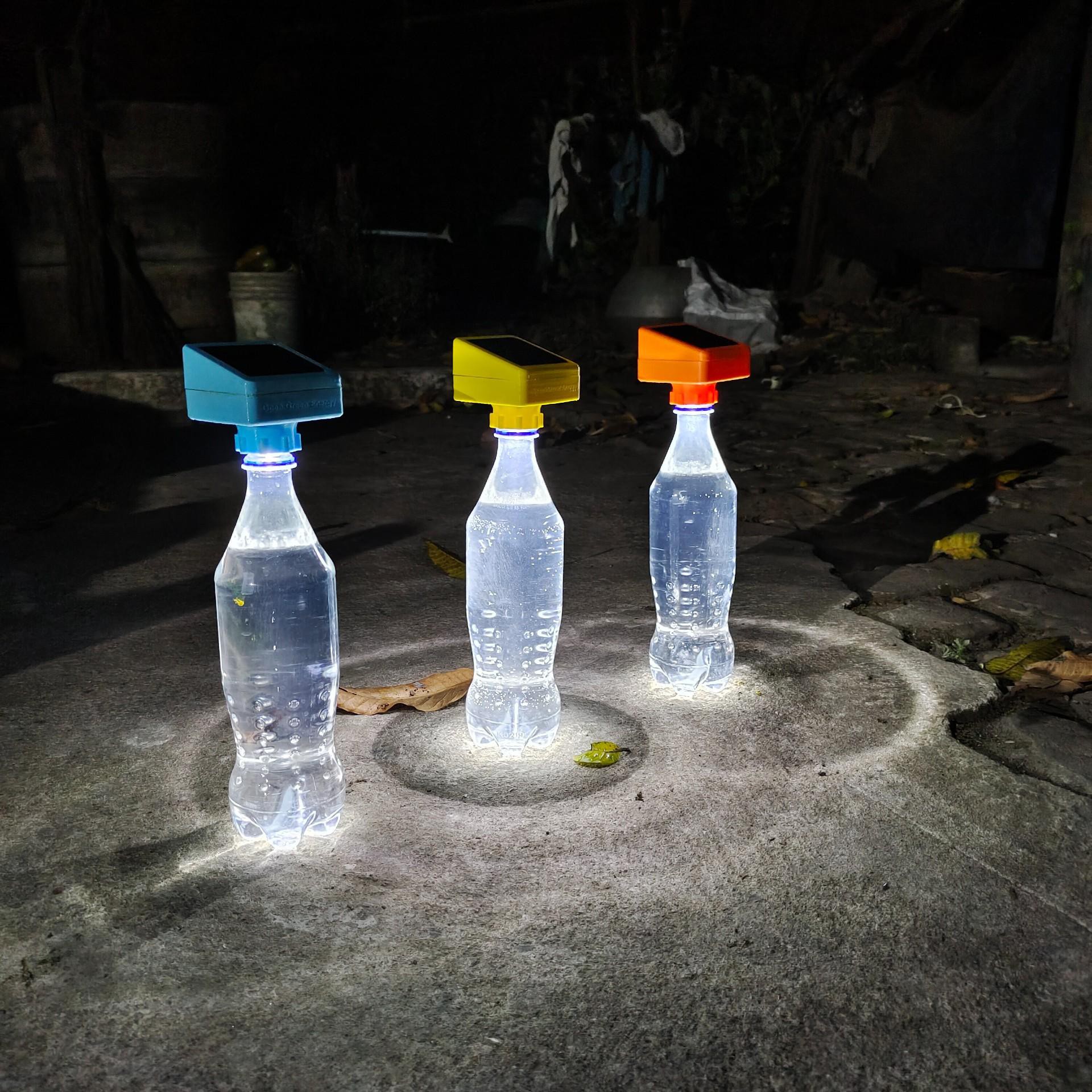
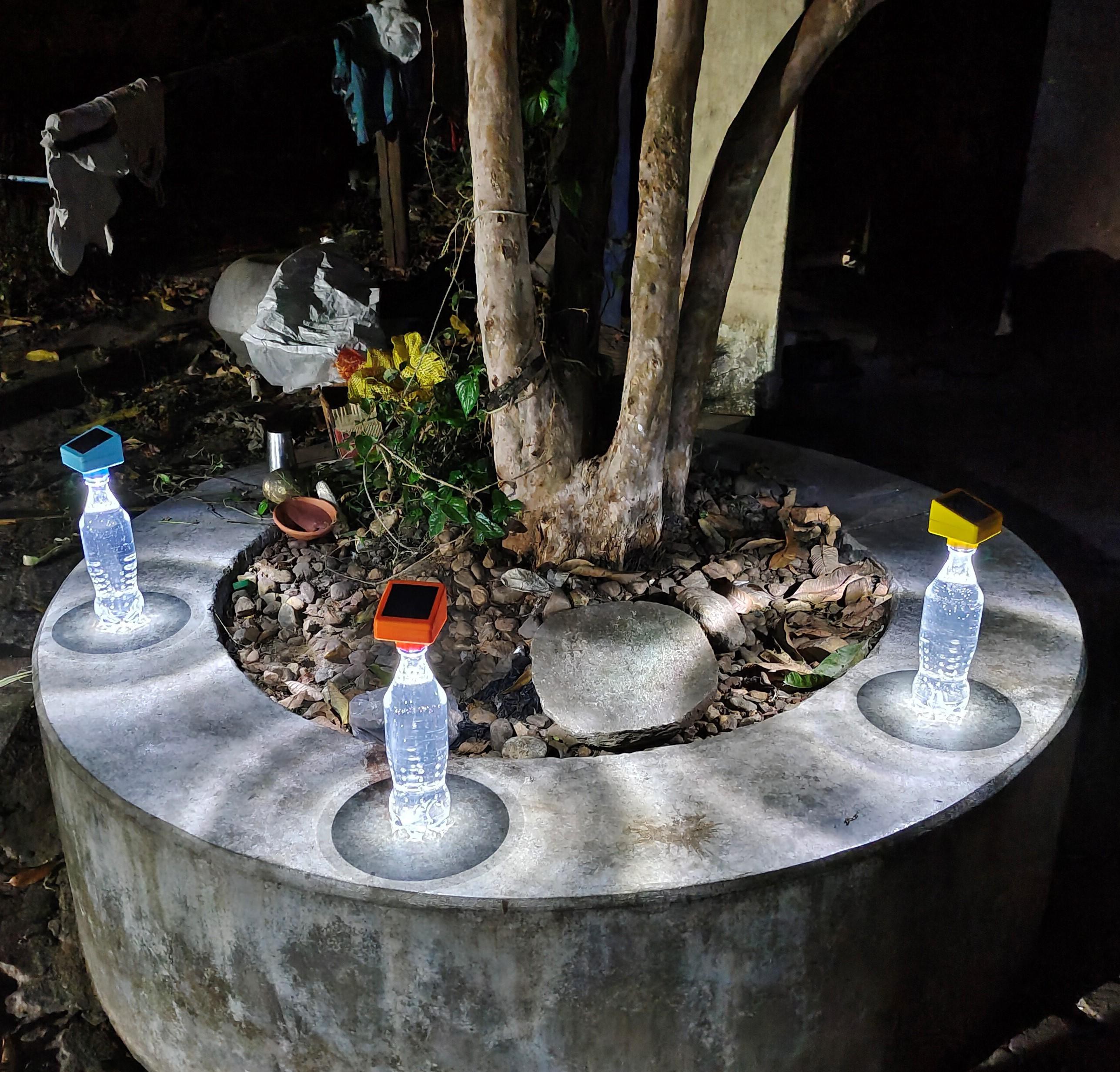
Before first use, charge the battery by placing the bottle lamps in bright sunlight for at least a day. Then turn on the button switch to set the desired brightness ( Low / High ). Place the bottle lamp at the desired location like a garden or pathways. The solar lamp will be automatically switched on when the sun goes down.
If you want to use this lamp for lighting the room, you can follow this Instructables to mount it on the roof.
-
3D Printed Enclosure Design
05/02/2022 at 18:11 • 0 comments![]()
![]()
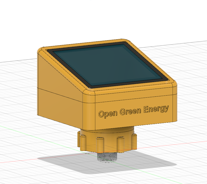
The enclosure for the solar lamp is designed in Autodesk Fusion 360. I have designed many iterations to get this design. The enclosure has 5 parts:
1. Main Body
2. Top Cover
3. LED Holder
4. Diffuser
5. Button
The Main Body is basically designed to fit all the components including the battery. The top cover is to cover up the main body and mount the solar panel on it. The LED holder is used to hold the LED and the diffuser is used to diffuse the LED light in all directions. The button is used to operate the switch on the PCB from outside.
Download the .STL files from Thingiverse.
-
PCB Design
05/02/2022 at 18:10 • 0 comments![]()
![]()
![]()
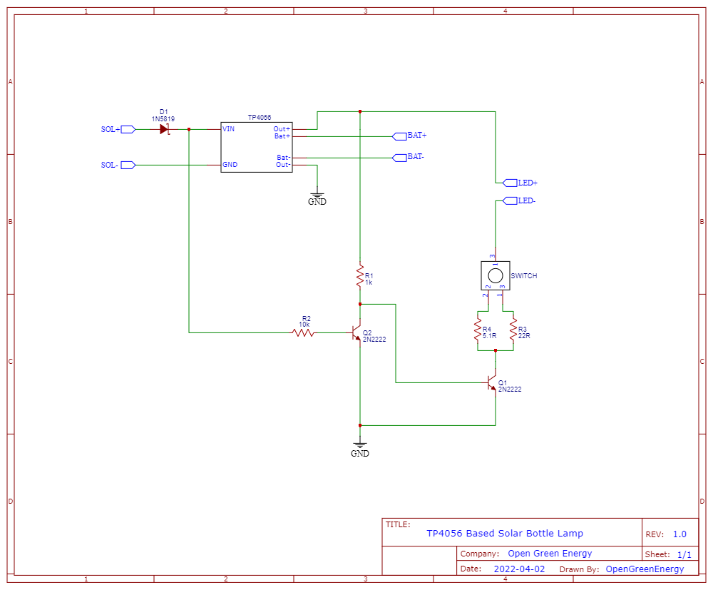
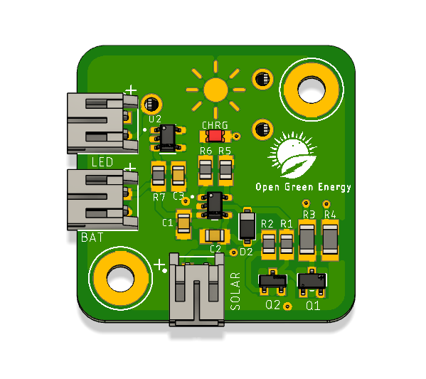
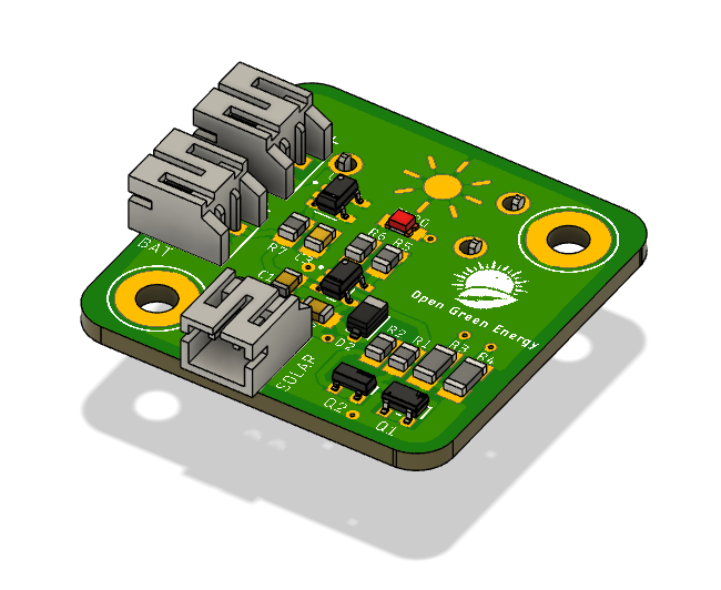
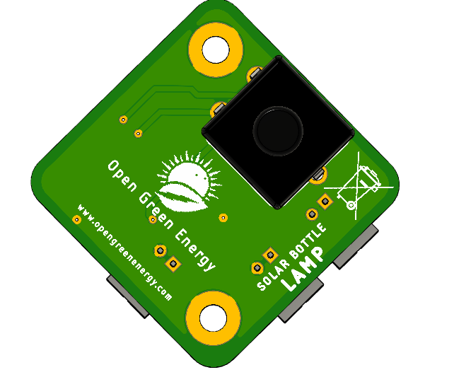
I have drawn the schematic by using Fusion 360 Electronics Design after that switched to PCB layout. I have placed all the SMD parts on the top side of the PCB and the button on the bottom side of the PCB. The main reason for placing the button switch on the bottom side is that it will be easier to access from outside of the enclosure. It also reduces the PCB board size.
I have ordered my PCB from PCBWay and received it within 7 days.
Download the Gerber files from PCBWay
DIY Solar Bottle Lamp
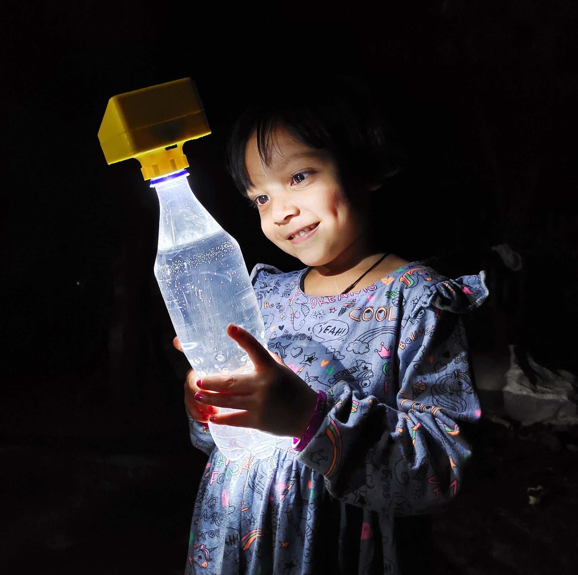
Solar Bottle Lamp is a solar-powered light that is constructed from waste plastic bottles. The design idea is to reuse waste plastic bottles
 Open Green Energy