Guillermo Perez Guillen
-
6. Test and Conclusion
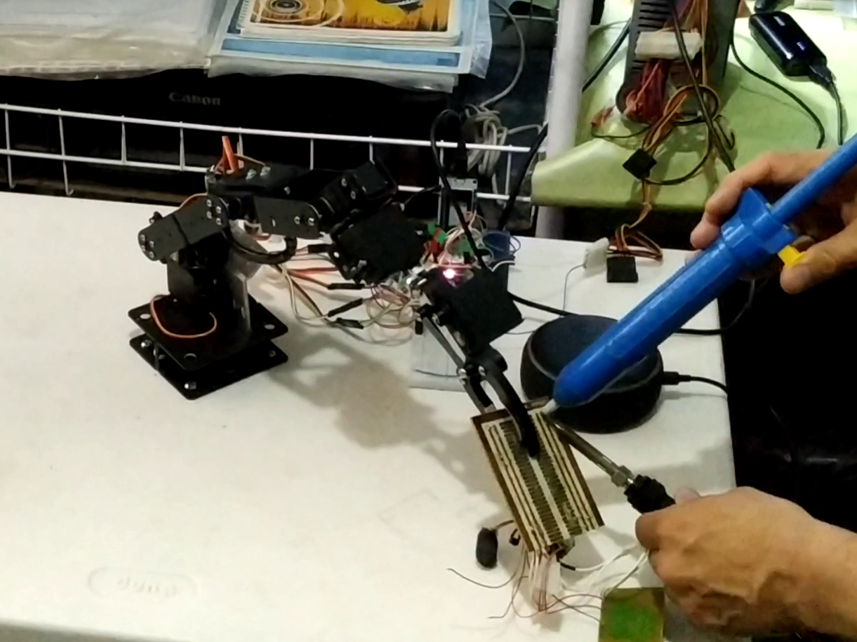
05/12/2022 at 04:22 • 0 commentsIn the video below I show you the tests with a PCD board and harvesting a connector.
Now, pick and place a box containing a lamp.
Finally, in the video below I show you the tests with a water bottle
Conclusion
- I have used free tools to develop a robotic arm that can help us in the tasks of an electronic workshop, eg:
- Achieve desoldering unusable PCB boards, where I have recovered and reused hundreds of components such as chips, capacitors, and resistors. The robotic arm has a stall torque of 8.5 kgfxcm (4.8V) and 10 kgfxcm (6V) in each servo, so the force used is less in manipulating PCB boards;
- The test of picking and moving a box with a lamp, I have used it as an experimental test, since I would really like it to pick and place the unsoldered electronic components, but in this case I will have to make modifications in the robotic arm clamp to achieve this effect; and
- The test of holding and moving a bottle has also served as an experimental test, since my intention is that it provides me with isopropyl alcohol to clean PCB boards and desoldered electronic components. Even I could develop a small fire system with this idea.
- Finally, I also have plans for the future with this innovative idea, but I will publish these in my next log.
-
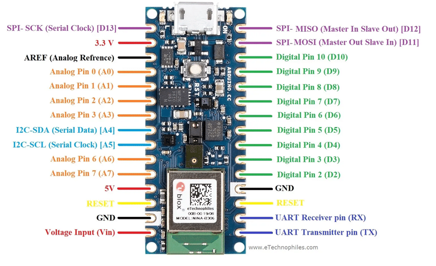
5. Code for Arduino NANO 33 BLE Sense board
05/12/2022 at 03:59 • 0 comments![]()
To programming the Arduino NANO 33 BLE Sense, I have used next code: robot-arm-arduinonano.ino
#include <Servo.h>

Servo myservo1;  // create servo1 object to control a servo1
Servo myservo2;  // create servo2 object to control a servo2
Servo myservo3;  // create servo3 object to control a servo3
Servo myservo4;  // create servo4 object to control a servo4
Servo myservo5;  // create servo5 object to control a servo5
Servo myservo6;  // create servo6 object to control a servo6

#define RED 22
#define BLUE 24
#define GREEN 23
#define LED_PWR 25

int pos1 = 90;    // variable to store the servo1 position - front
int pos2 = 90;    // variable to store the servo2 position - vertical
int pos3 = 90;    // variable to store the servo3 position - vertical
int pos4 = 150;   // variable to store the servo4 position - vertical
int pos5 = 90;    // variable to store the servo5 position - vertical
int pos6 = 20;    // variable to store the servo6 position - gripper close

const int buttonPin1 = 4;     // the number of the pushbutton pin
const int buttonPin2 = 7;     // the number of the pushbutton pin
const int buttonPin3 = 8;     // the number of the pushbutton pin
const int buttonPin4 = 12;    // the number of the pushbutton pin
const int buttonPin5 = 13;    // the number of the pushbutton pin
const int buttonPin6 = 2;     // the number of the pushbutton pin

int buttonState1 = 0;         // variable for reading the pushbutton status
int buttonState2 = 0;         // variable for reading the pushbutton status
int buttonState3 = 0;         // variable for reading the pushbutton status
int buttonState4 = 0;         // variable for reading the pushbutton status
int buttonState5 = 0;         // variable for reading the pushbutton status
int buttonState6 = 0;         // variable for reading the pushbutton status

void setup() {
  myservo1.attach(3);  // attaches the servo on pin 3 to the servo object
  myservo2.attach(5);  // attaches the servo on pin 5 to the servo object
  myservo3.attach(6);  // attaches the servo on pin 3 to the servo object
  myservo4.attach(9);  // attaches the servo on pin 3 to the servo object
  myservo5.attach(10); // attaches the servo on pin 3 to the servo object
  myservo6.attach(11); // attaches the servo on pin 3 to the servo object

  pinMode(buttonPin1, INPUT);
  pinMode(buttonPin2, INPUT);
  pinMode(buttonPin3, INPUT);
  pinMode(buttonPin4, INPUT);
  pinMode(buttonPin5, INPUT);
  pinMode(buttonPin6, INPUT);

// intitialize the digital Pin as an output
pinMode(RED, OUTPUT);
digitalWrite(RED, LOW);

pinMode(BLUE, OUTPUT);
digitalWrite(BLUE, LOW);

pinMode(GREEN, OUTPUT);
digitalWrite(GREEN, LOW);

pinMode(LED_PWR, OUTPUT);
digitalWrite(LED_PWR, LOW);
}

void loop() {
  // read the state of the pushbutton value:
  buttonState1 = digitalRead(buttonPin1);
  buttonState2 = digitalRead(buttonPin2);
  buttonState3 = digitalRead(buttonPin3);
  buttonState4 = digitalRead(buttonPin4);
  buttonState5 = digitalRead(buttonPin5);
  buttonState6 = digitalRead(buttonPin6);

  // check if the button is is HIGH:
  if (buttonState1 == HIGH) {
    // MOVE THE OBJECT (BOX)
    digitalWrite(LED_PWR, LOW);
    digitalWrite(GREEN, LOW);
    digitalWrite(BLUE, LOW);
    digitalWrite(RED, HIGH);


  } else  {
    // END
    digitalWrite(RED, LOW);
    digitalWrite(GREEN, LOW);
    digitalWrite(BLUE, LOW);
    digitalWrite(LED_PWR, HIGH);
    delay(10);
  }
}
You can get the codes on the download section or the github account of the main post.
-
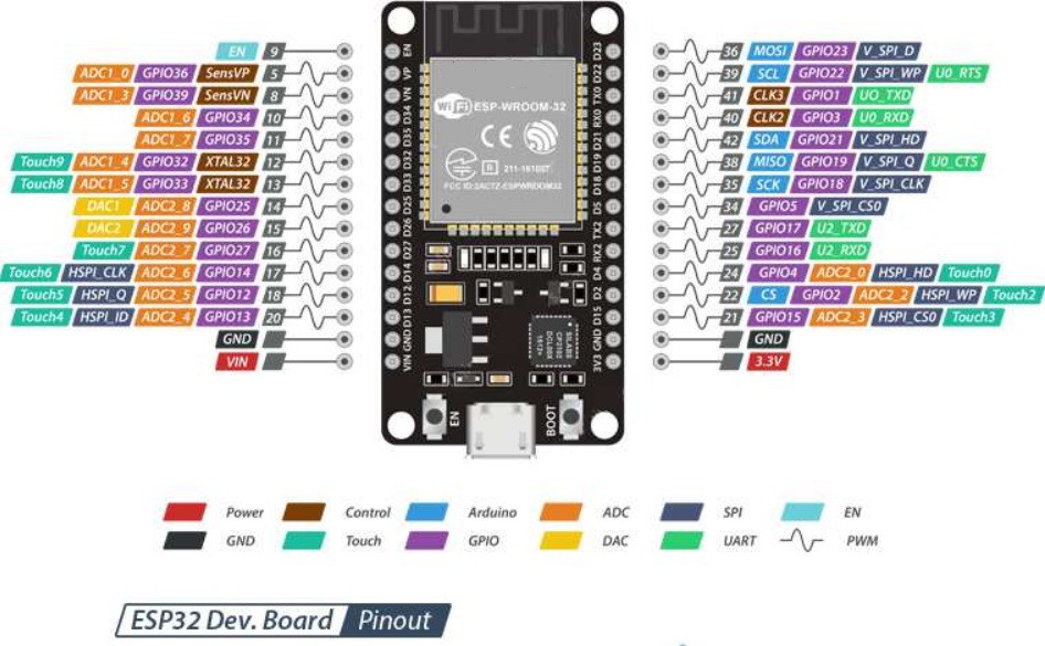
4. Code for ESP32 board
05/12/2022 at 03:52 • 0 comments![]()
To programming the ESP32-WROOM-32 I have used next code: robot-arm-esp32.ino
// AUTHOR: GUILLERMO PEREZ GUILLEN

#include <Arduino.h>
  #include <WiFi.h>
  #define LED_BUILTIN 2 // define the GPIO 2 as LED_BUILTIN
  #define RELAY_PIN_3 17  // LAMP 3
  #define RELAY_PIN_4 18  // LAMP 4
  #define RELAY_PIN_5 19  // LAMP 5
  #define RELAY_PIN_6 21  // LAMP 6

#include <fauxmoESP.h>
#define SERIAL_BAUDRATE 115200
#define WIFI_SSID "*********"
#define WIFI_PASS "************"
#define LAMP_1 "box" //
#define LAMP_2 "breadboard" //
#define LAMP_3 "bottle" //
//#define LAMP_4 "lamp four" //

fauxmoESP fauxmo;

// Wi-Fi Connection
void wifiSetup() {
  // Set WIFI module to STA mode
  WiFi.mode(WIFI_STA);

  // Connect
  Serial.printf("[WIFI] Connecting to %s ", WIFI_SSID);
  WiFi.begin(WIFI_SSID, WIFI_PASS);

  // Wait

  Serial.println();

  // Connected!
  Serial.printf("[WIFI] STATION Mode, SSID: %s, IP address: %s\n", WiFi.SSID().c_str(), WiFi.localIP().toString().c_str());
}

void setup() {

  // Init serial port and clean garbage
  Serial.begin(SERIAL_BAUDRATE);
  Serial.println();

  // Wi-Fi connection
  wifiSetup();

  // LED

  pinMode(LED_BUILTIN, OUTPUT); // initialize GPIO pin 2 LED_BUILTIN as an output.
  digitalWrite(LED_BUILTIN, HIGH);   // turn the LED on


  // Add virtual devices
  fauxmo.addDevice(LAMP_1);
  fauxmo.addDevice(LAMP_2);
  fauxmo.addDevice(LAMP_3);
//  fauxmo.addDevice(LAMP_4);

  fauxmo.onSetState([](unsigned char device_id, const char * device_name, bool state, unsigned char value) {
    // Callback when a command from Alexa is received.
    // You can use device_id or device_name to choose the element to perform an action onto (relay, LED,...)
    // State is a boolean (ON/OFF) and value a number from 0 to 255 (if you say "set kitchen light to 50%" you will receive a 128 here).
    // Just remember not to delay too much here, this is a callback, exit as soon as possible.
    // If you have to do something more involved here set a flag and process it in your main loop.

    Serial.printf("[MAIN] Device #%d (%s) state: %s value: %d\n", device_id, device_name, state ? "ON" : "OFF", value);

////////// MOVE THE BOX //////////
    if ( (strcmp(device_name, LAMP_1) == 0) ) {
      Serial.println("RELAY 1 switched by Alexa");
      if (state) {
        digitalWrite(RELAY_PIN_1, HIGH);
        delay(1000);
        digitalWrite(RELAY_PIN_1, LOW);
      } else {
        digitalWrite(RELAY_PIN_2, HIGH);
        delay(1000);
        digitalWrite(RELAY_PIN_2, LOW);
      }
    }


void loop() {
  static unsigned long last = millis();
  if (millis() - last > 5000) {
    last = millis();
    Serial.printf("[MAIN] Free heap: %d bytes\n", ESP.getFreeHeap());
  }
}
Dont forget to insert the credentials of your modem in the Wi-Fi.
#define WIFI_SSID "*********"
#define WIFI_PASS "************"
-
3. Software
05/12/2022 at 03:38 • 0 commentsPrerequisites
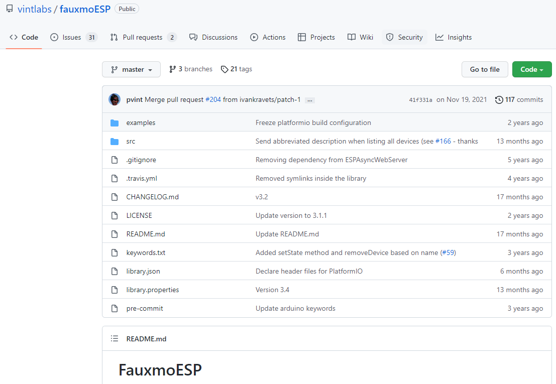
The FauxmoESP
To control the ESP32 with Alexa Echo Dot, you need to install the FauxmoESP library. This library emulates a Belkin Wemo device, allowing you to control your ESP32 using this protocol. This way, the Echo Dot instantly recognizes the device, after uploading the code, without any extra skills or third party services. You can read more about FauxmoESP here:
https://bitbucket.org/xoseperez/fauxmoesp/src/master/
https://github.com/vintlabs/fauxmoESP
![]()
Installing the ESP32 Board in Arduino IDE
In order to upload code to your ESP32 using Arduino IDE, you should install an add-on for the Arduino IDE that allows you to program the ESP32 using the Arduino IDE and its programming language. You can read more about Installing the ESP32 Board in Arduino IDE here:
https://randomnerdtutorials.com/installing-the-esp32-board-in-arduino-ide-windows-instructions/
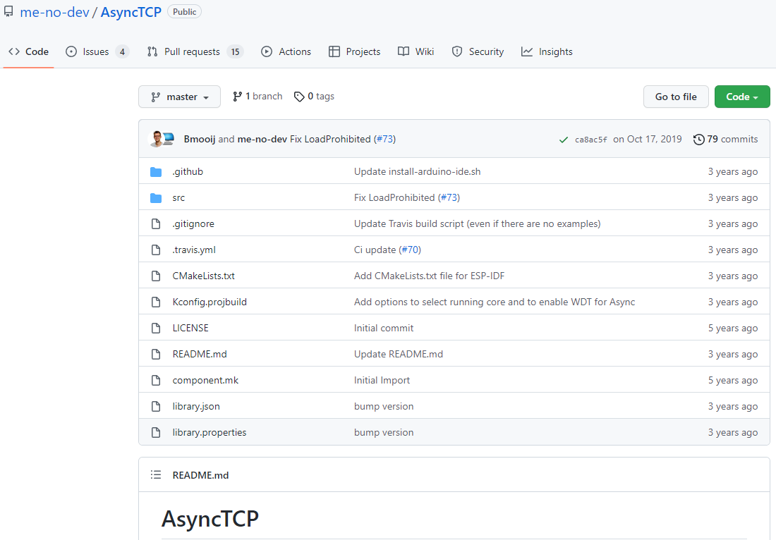
Installing the AsyncTCP Library
You also need to install the AsyncTCP Library. You can read more about Installing the AsyncTCP Library here:
https://github.com/me-no-dev/AsyncTCP
![]()
-
2. Hardware
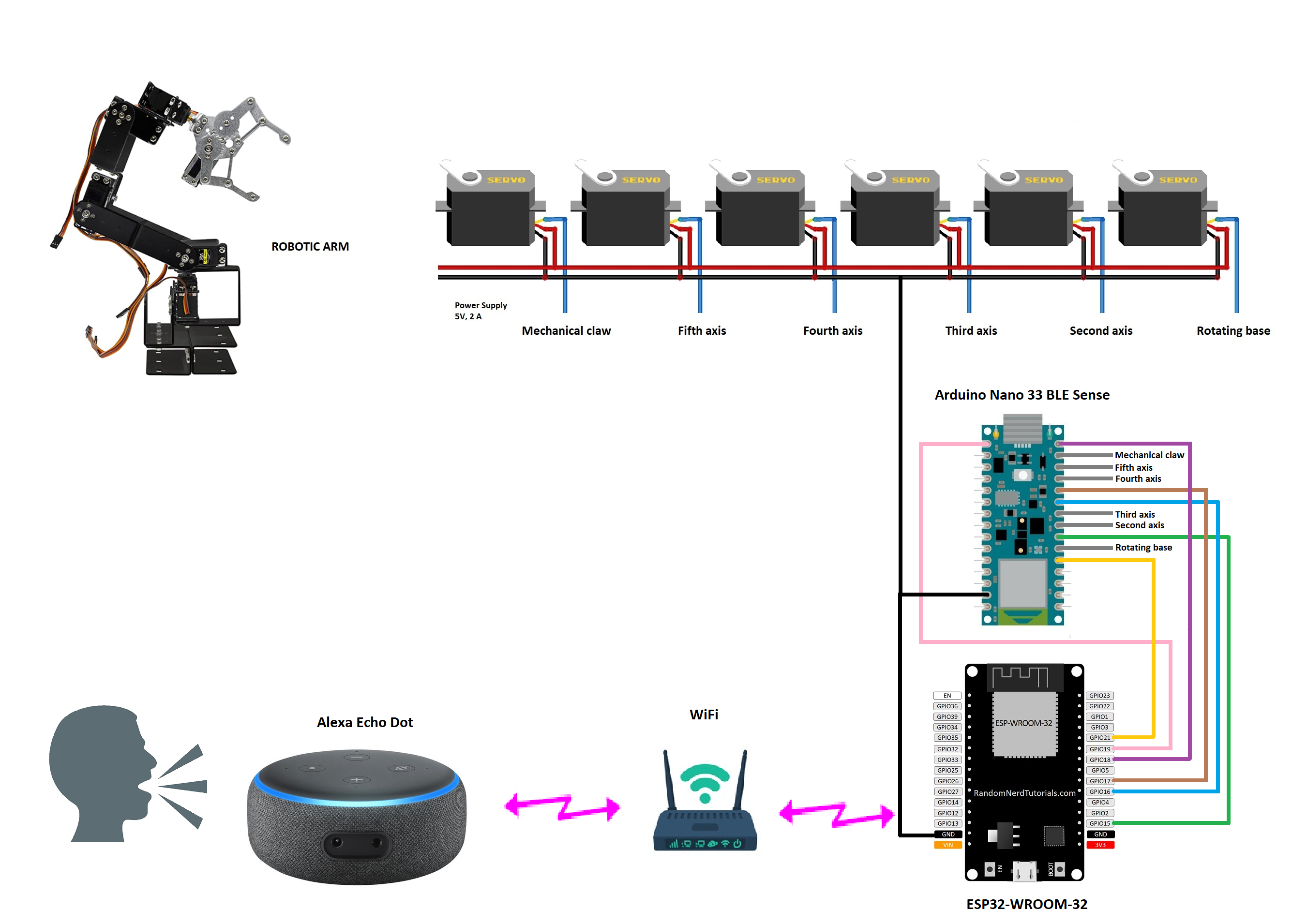
05/12/2022 at 03:35 • 0 commentsThe schematic diagram below shows the electrical connections of the electronic components.
![]()
How does it work?
- We use voice commands to perform three functions: 1) controlling a bottle; 2) controlling a board; and 3) controlling a box.
- The voice commands are activated through Alexa Echo Dot, and they reach the ESP32-WROOM-32 board via WiFi.
- Finally, these voice commands are transmitted to the Arduino Nano 33 BLE Sense board, which controls the robot arm.
-
1. Introduction
05/12/2022 at 03:29 • 0 commentsA cobot, or collaborative robot, is a robot intended for direct human robot interaction within a shared space, or where humans and robots are in close proximity. Cobot applications contrast with traditional industrial robot applications in which robots are isolated from human contact. Cobot safety may rely on lightweight construction materials, rounded edges, and inherent limitation of speed and force, or on sensors and software that ensures safe behavior.
Cobots can have many uses, from information robots in public spaces, logistics robots that transport materials within a building, to industrial robots that help automate unergonomic tasks such as helping people moving heavy parts, or machine feeding or assembly operations.
![]()
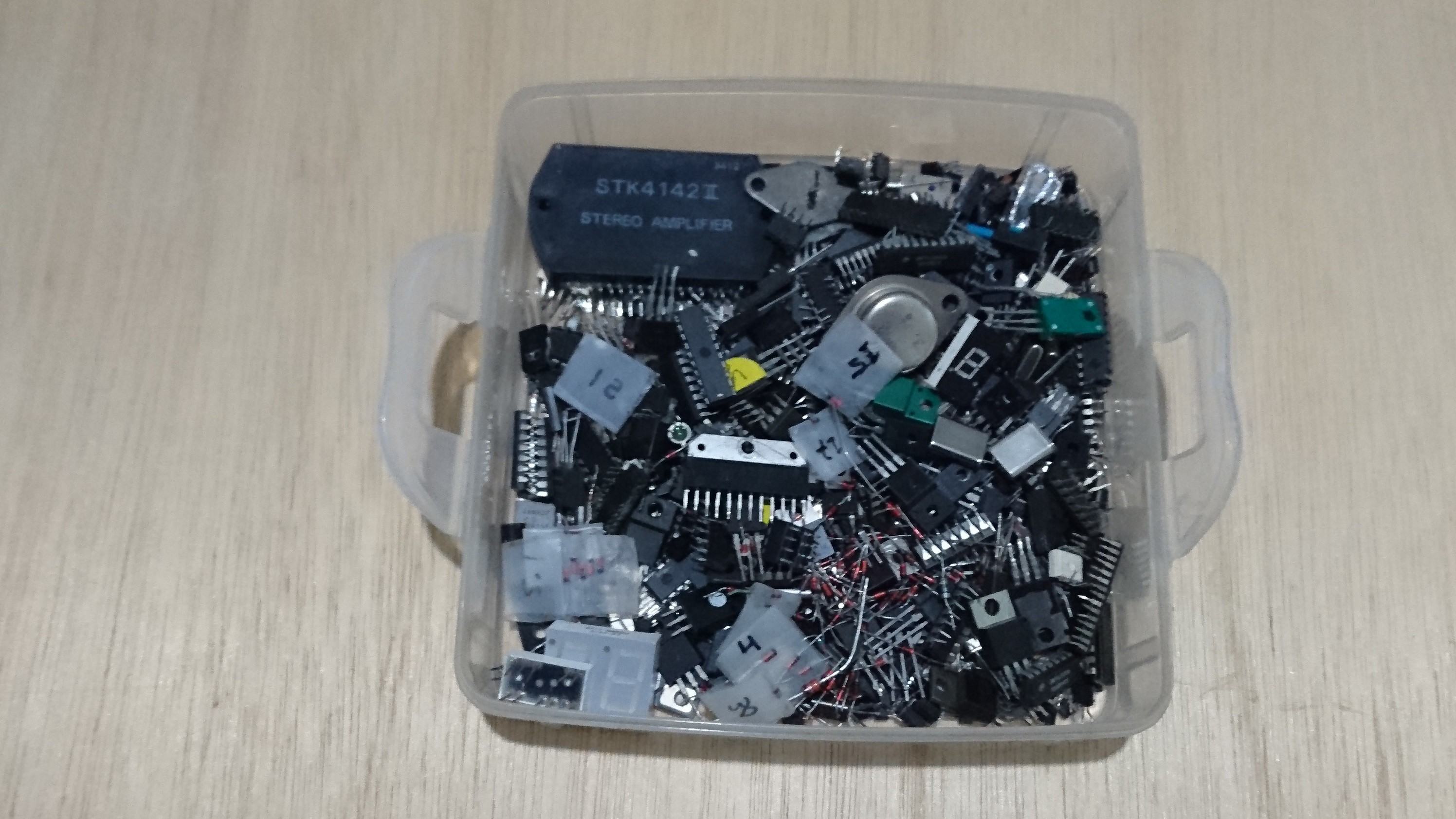
In my case, the innovation consists of developing a collaborative robot for home use that helps me in my tasks of extracting electronic components from unusable PCB boards. By this method I have managed to recover chips, transistors, and diodes as shown in the image below.
![]()
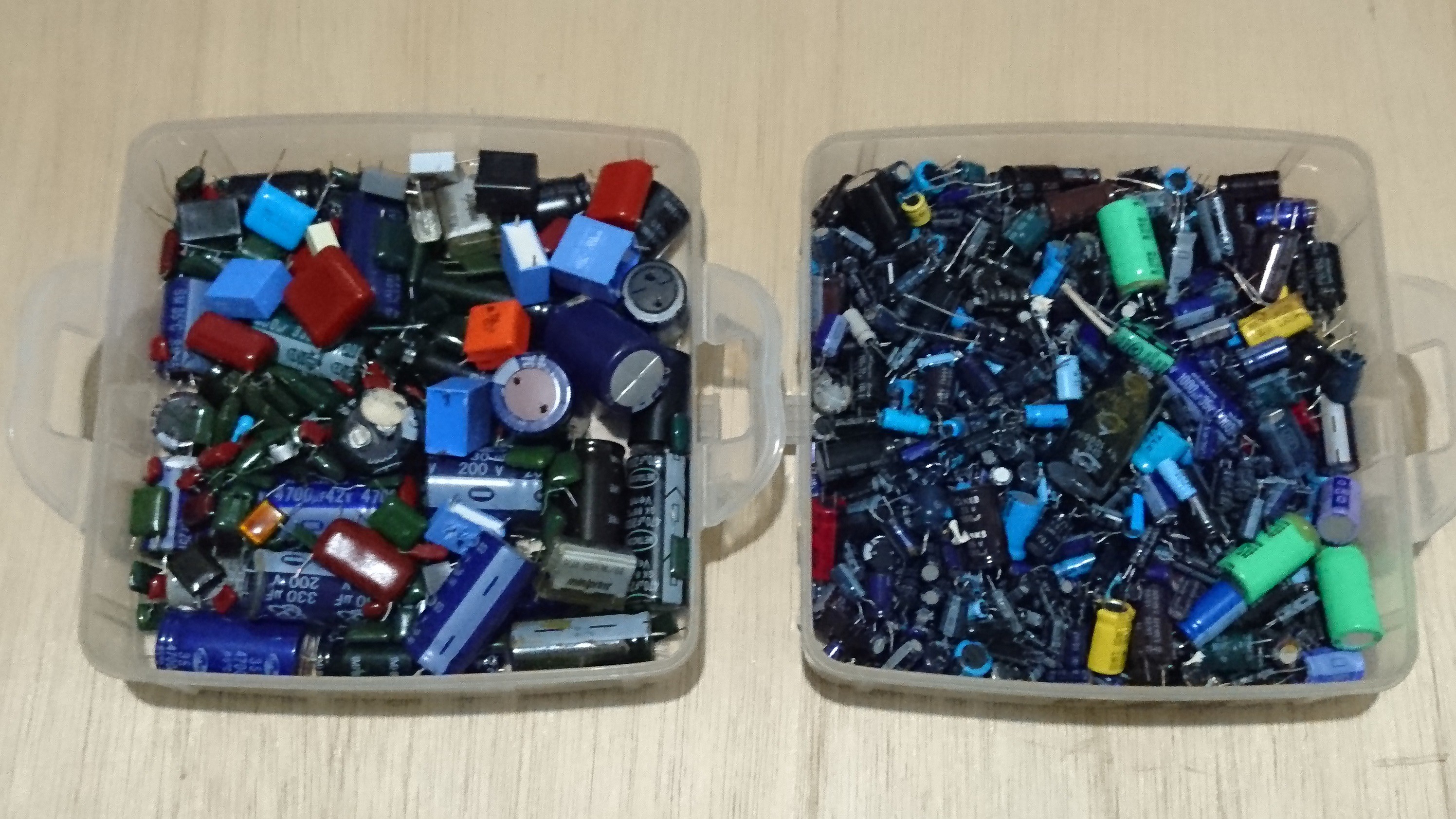
I have also recovered electrolytic and ceramic capacitors.
![]()
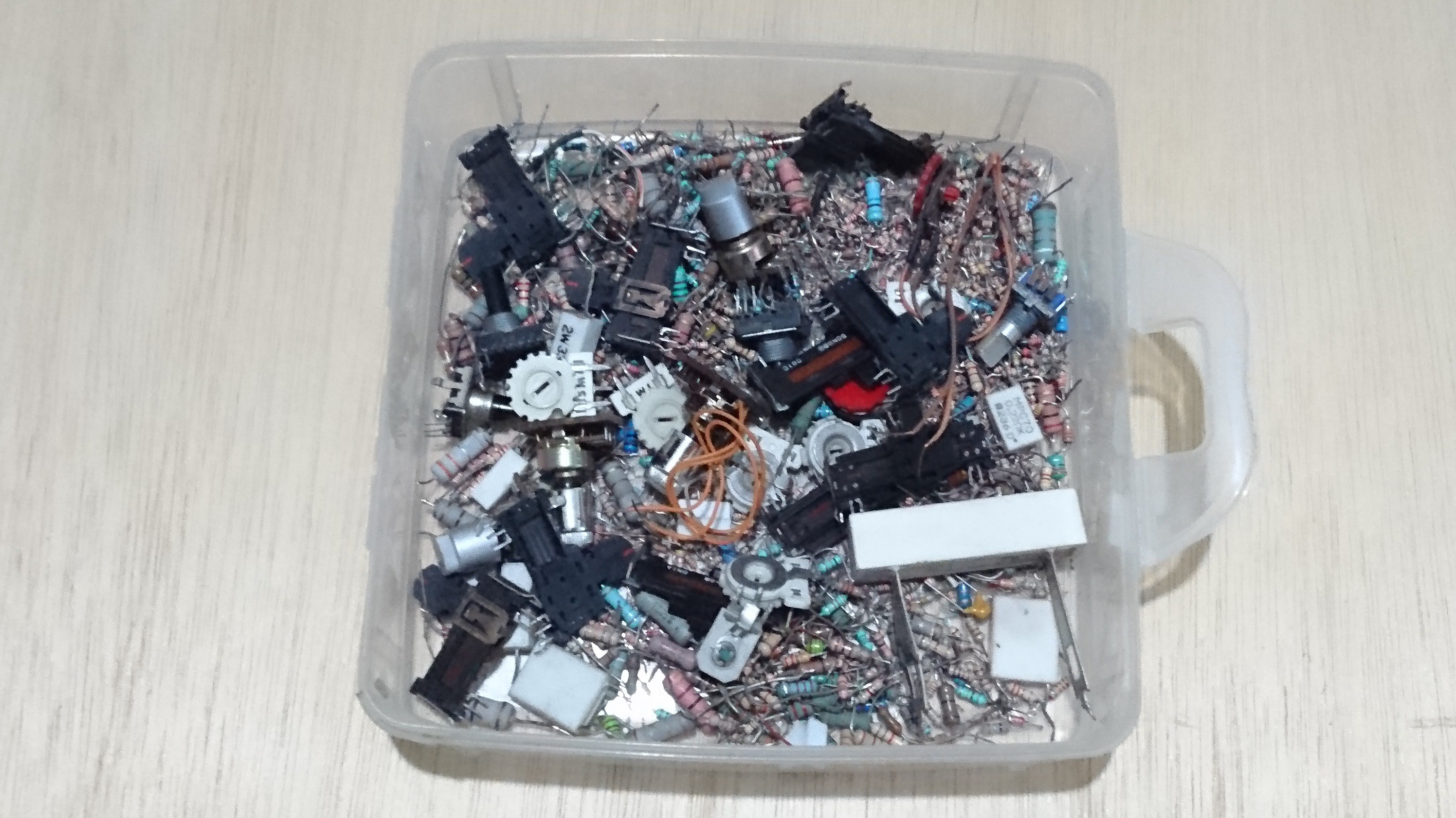
Even a few hundred resistors and potentiometers of different values and types.
![]()
Robotic Arm for Electronic Workshop
Collaborative Robotic Arm with Artificial Intelligence (AI), and Used as Assistant in an Electronic Workshop by Voice Commands