 Alain d'Espaignet
-
21Cavity Fusion 360 models
After replacing cavity models generate a new 3D PCB from EAGLE to Fusion 360. The result of this process is:
![]()
You see the difference between the 3D for realistic visualization vs 3D for cavity plate creation.
Incidentally if you are following carefully you'll notice that I missed the mark on making the LED and connector extrude high enough to make an opening in the cavity plate. I am not going to fix that now.
-
22Create a cavity plate
Fusion 360 interprets and treats 3D PCB’s generated from EAGLE in a special way. You are in 3D PCB land at this point and there are only a few edit operations you can do: Flip components, Move components, drill holes, edit the board shape.
We need to create a cavity plate on top of the PCB and make it a bit higher than the highest part on the board.
For this we need to be in Fusion 360 Design land. One way to achieve this is to export the whole 3D PCB as a STEP file then Open it. This process yields this result:
![]()
Again these “gymnastics” steps are necessary due to the inherent limitations in Fusion 360 in handling the process I am introducing. Fusion 360 was not made to create cavity plates but I believe it can be streamlined to do so with software and the API provided.
We are now back in DESIGN land yet we have preserved the ability to select and modify the PCB parts individually.
Now we can create a sketch and extrude it to become the cavity plate. It should be as high as the highest part with some extra.
I’ll make the cavity plate a bit larger than the PCB so that the latter “clips” into the cavity mold.
![]()
-
23Boolean Cut Out
We are now ready to perform the boolean cut out operation. The body to be cutout is the cavity plate created above. The cavity 3D models will serve as cutting tools in the boolean operation.
![]()
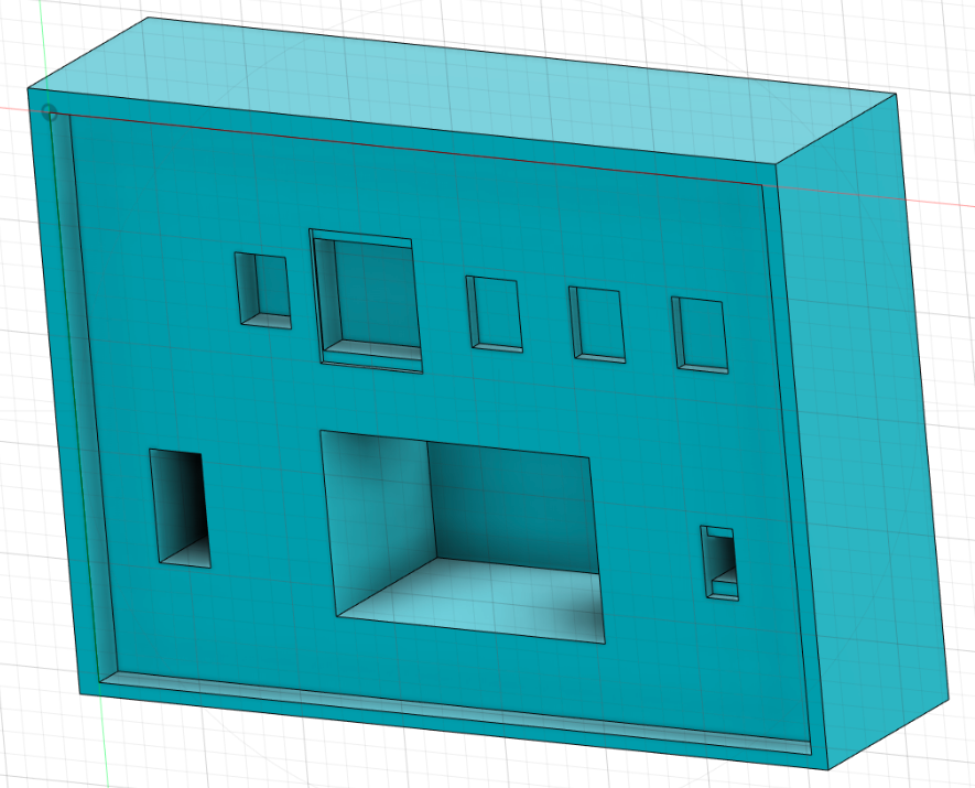
There is a small artifact resulting from the boolean operation that is related to the through holes for the connector. We can easily select and remove that. So here is the final cavity plate.
![]()
This cavity plate when clipped over the PCB will retain all the parts in place. The pins will make contact with the PCB SMD pads.
The circuit should in principle work.
-
24Assembly
To visualize the assembly, export the cavity plate and merge it with the exported original realistic 3D PCB parts.
![]()
-
25Finally
All we need to do now is:
- 3D print or CNC mill the cavity plate.
- Get the PCB made.
- Acquire the parts.
- Place the parts upside down in their respective cavities.
- Place the PCB on top.
- Apply a thin layer of glue (optional). This will keep it air tight so the surfaces will not corrode inside.
- Clip the PCB into the cavity plate.
- Press it together until the glue dries.
This is it.
The advantage is now that we can crack the whole thing apart and replace and or reuse every component.
-
26Plate material
The plate material must be chosen carefully. It should be rigid enough so that it has the strength to press the parts against the PCB.
-
273D printing
3D printing is a good candidate. There may be some precision limitations to consider. Also it may be hard to create small features accurately. These can only be figured out by testing various materials.
-
28CNC milling
CNC is also an option. I had a small Sherling 2000 CNC machine. I could mill using 10 thou bits with it.


Discussions
Become a Hackaday.io Member
Create an account to leave a comment. Already have an account? Log In.