Close
0%
0%

Joy232

Print using RS232 on the joystick port of MSX computers

Similar projects worth following
This program allows you to send your code listing serially through the joystick port of MSX computers by intercepting the LPRINT instruction from the BASIC interpreter.
The data is bitbanged in accordance with RS232 standard and it is possible to use speeds from 1200 to 19200 bauds.
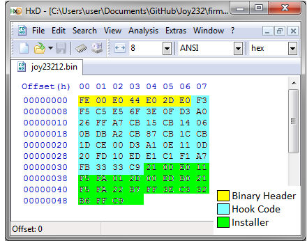
The program is written in Z80 assembly and takes only 75 bytes including the binary file header and the hook code installer. The bitbang code itself takes only 44 bytes.
It can be connected directly to an USB-to-serial dongle, but the connection with a standard RS232 port can be done by a MAX232 or a single transistor voltage level converter.

The BASIC interpreter of MSX computers was designed to allow the expansion of many of its functionalities by using hooks, which are addresses called from strategic locations within the BIOS. Each hook code takes 5 RAM addresses that are initialized with Z80 RET instrucions. Then to expand a given function it is necessary to replace the RET instructions by a CALL to the address where the expansion code is located.

The HLPT is located at address 0xFFB6 and it is called by the LPTOUT function which is the standard routine to output a character to the line printer via the Centronics Port. Any instruction of the BASIC interpreter that uses the printer make a call to the LPTOUT function and hence make a call to the HLPT hook.

The Joy232 code is straightforward. The first time it runs it replaces the RET instructions on the HLPT hook by a CALL to the address of memory where the serial transmission is performed. After the hook code is installed any character sent to the printer will be sent serially to one pin of the joystick port.

The bitbang code concatenates a bit sequence composed by the start bit, the data bits and the stop bit into a 16 bit register. Next each bit is transmitted until 10 bits have passed. After the last bit is sent the routine ends and the control returns to the BIOS.

The baudrate can be controlled by changing the value BAUD either on compilation time or by a poke (after the hook code is already installed). The lowest baudrates allow some tolerance on such value which is indeed used in a delay loop.

The program can be loaded on the MSX machine as a binary (using BLOAD instruction) or can be typed in from a BASIC prompt.

JOY23213.BAS

MSX Basic program to install the hook code for print using RS232 on Joystick port.

bas - 842.00 bytes - 12/20/2016 at 00:35

Download

joy23213.bin

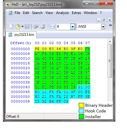
MSX binary program to install the hook code for print using RS232 on Joystick port. This version uses optional parity control

octet-stream - 93.00 bytes - 12/19/2016 at 22:41

Download

  • 1 × USB to Serial Adapter
  • 1 × DB-9 female

  • Complete BASIC program

    danjovic12/20/2016 at 00:43 0 comments

    I have wrote a complete BASIC program for loading the hook code using the MSX and used "LLIST" command to transfer the program to the PC using the hook code itself.

    This version was named "complete" because it has instructions on how to change the baudrate and how to use parity

    10 REM
    20 REM Joy232 hook code
    30 REM danjovic 2016
    40 REM version 1.31 19/12/2016
    50 REM
    60 EI=&HFAF5:SIZE=63
    70 FOR A = EI TO EI+SIZE
    80 READ B$: POKE A,VAL("&H"+B$)
    90 NEXT A
    100 REM
    110 POKE &HFFB8,&HFA
    120 POKE &HFFB7,&HF5
    130 POKE &HFFB6,&HC3
    140 REM
    150 DATA F3,F5,C5,E5,6F,3E,0F,D3
    160 DATA A0,26,FF,A7,CB,15,CB,14
    170 DATA 06,0B,DB,A2,CB,87,CB,1C
    180 DATA CB,1D,CE,00,D3,A1,0E,11
    190 DATA 0D,20,FD,10,ED,E1,C1,F1
    200 DATA A7,FB,33,33,C9,CE,00,D3
    210 DATA A1,0E,06,0D,20,FD,10,ED
    220 DATA E1,C1,F1,FB,33,33,C9,00
    230 REM
    240 REM To change baudrate
    250 REM
    260 REM POKE &HFB27,value
    270 REM
    280 REM Baudrate  value
    290 REM 1200      170
    300 REM 2400      83
    310 REM 4800      39
    320 REM 9600      17
    330 REM 14400     10
    340 REM 19200      6
    350 REM
    360 REM ----------------------
    370 REM To use parity
    380 REM
    390 REM POKE &HF96D,value
    400 REM
    410 REM Parity    value
    420 REM NONE        0 (or 1)
    430 REM EVEN        2
    440 REM ODD         3

  • Testing the baudrates

    danjovic12/19/2016 at 23:55 0 comments

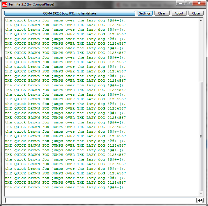
    I have used a BASIC program to test the baudrates.

    10 REM test transmission baudrates
    20 BDR = &HFB27
    30 REM Baudrate Value
    40 REM 1200     170
    50 REM 2400     83
    60 REM 4800     39
    70 REM 9600     17
    80 REM 14400    10
    90 REM 19200     6
    100 REM
    110 POKE(BDR),17
    120 LPRINT "THE QUICK BROWN FOX JUMPS OVER THE LAZY DOG 01234567"
    130 LPRINT "the quick brown fox jumps over the lazy dog !@#+-()."
    140 GOTO 120
    The code worked in all speeds with the given values for the delay loop. but I have tested some values around and verified that above 9600 bauds such value is very critical.


  • New fluxogram

    danjovic12/19/2016 at 23:07 0 comments

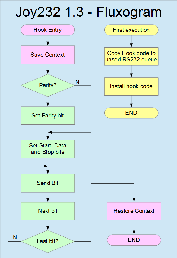
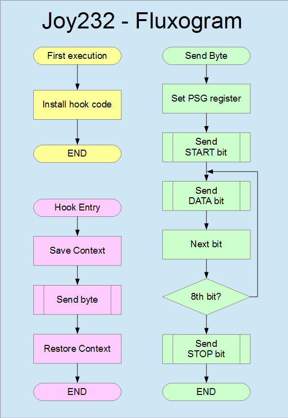
    New fluxogram to reflect the last version of the code. The colors from latter fluxogram have been kept to ease the comparison.

  • In Soviet Russia.... BIOS uses your software.

    danjovic12/19/2016 at 22:39 0 comments

    This post is to remember the contest judges that my code does not use the BIOS from MSX computers to print the character, but the opposite! BIOS use my software.

    I may use BIOS to load the code to memory but this is the same circumstance of the Arduino or the Parallax bootloader :)

    Spasiba!

  • Added parity control

    danjovic12/19/2016 at 22:19 0 comments

    Added configurable parity control. Parity can be NONE, EVEN or ODD, selectable by contents of address 0F96DH which RS232 Queue Putback flag that is not used by MSX BIOS.
    The hook code size is 63 bytes and can still fit within unused RS232 Queue space (64 bytes). The entire binary takes 93 bytes.

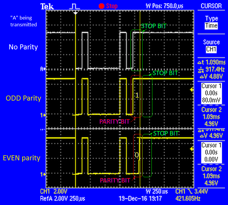
    Parity was checked using oscilloscope and a BASIC program .

    10 REM test transmission with parity
    20 CNF = &HF96D
    30 REM
    40 REM 0/1: no parity   (N)
    50 REM   2: even parity (E)
    60 REM   3: odd parity  (O)
    70 REM
    80 POKE(CNF),2
    90 LPRINT "A";
    100 GOTO 90

  • Code profile

    danjovic12/13/2016 at 04:44 0 comments

    The enhanced code takes only 75 bytes, from which 7 are the binary header file, 23 are for transfering the hook code to the unused RS232 queue. The hook code itself takes only 44 bytes.

  • Further enhancement

    danjovic12/12/2016 at 20:37 0 comments

    After optimization the size of the loadable binary file shrinked to only 65 bytes being 7 for the file header, 14 for hook code installer and 44 for the hook code itself which is small enough to fit whithin the unused 64 bytes reserved for the rs232 queue in 'system variables' area.

    ;
    ; Install bitbang routine on printer HOOK
    ; Borrowed from the book "+50 dicas para o MSX"
    ;
    HLPT:  EQU 0FFB6H ; Printer hook entry
    RS2IQ: EQU 0FAF5H ; RS232 queue, 64 bytes
    
    ;
    INSTALL:
    LD HL, HOOK_PRNTJ232           ; beginning of hook code
    LD DE, RS2IQ                   ; destiny, unused rs232 queue
    LD BC, HOOK_END-HOOK_PRNTJ232  ; block size
    LDIR                           ; transfer hook code to its new location
    
    
    LD HL,RS2IQ     ; Write the execution entry point for printer hook
    LD [HLPT+1],HL
    LD A,0C3H       ; then write the CALL instruction (0xC3)
    LD [HLPT],A
    RET

    The downside is that now we need 10 extra bytes of instructions to move the hook code from the load address to the rs232 queue area. Another necessary modification was on the bit delay loop which used an absolute address jump to simplify the timing (JP NZ,xxxx takes 11 cycles either jump or no jump) . It was replaced by a relative jump (JR NZ,xxxx) .

       ; delay 1 bit time
       LD C,T9600     ;   8     8      poke here to change the baud rate
       DELAY_C:
       DEC C          ; ( 5)
       JR NZ,DELAY_C  ; (12)(/7)
                      ;  (12+5)*(TDelay-1)+(7+5) = 17*TDelay - 17 + 12 = (17*Tdelay-5)
    
    DJNZ SEND_BITS    ; 14(/9)         send next bit

    The relative jump made the hook code relocatable (now it can be copied and executed from wherever address) and the new timing due to the relative jump ended by enhancing the error rate for 14400 and 19200 baud are now both under 2% of error (it was not intentional though).

    Clock = 3.575611 MHz
                     
    Baud   Tdelay  Cycles RealRate  Error %
    1200    170    2971   1203,50    0,29
    2400     83    1492   2396,52   -0,14
    4800     39     744   4805,92    0,12
    9600     17     370   9663,81    0,66
    14400    10     251   14245,4   -1,07
    19200     6     183   19538,8    1,76
    

    I could have loaded the hook code directly in the rs232 queue along with the installation code (14+44 bytes) , but I am planning to use the remaining 20 bytes to allow extra stuff like parity.

  • Squeezing the code because 85 bytes is too many...

    danjovic12/10/2016 at 14:17 0 comments

    I have started to squeeze the hook code. This can be done by merging the start, stop and data bits into a 16 bit register and use the same loop to transmit all the bits from the RS232 character (i.e. 10 bits). It also has a positive side effect that now all the bits will last exactly the same time (the stop bit may linger but it doesn't really matter as long as it takes at least 1 bit time.

    Then the bitbang code turns into:

    SND232:
    ; Inputs:
    ; L: Byte to be sent  
    ; 
    ; Changes: AF, BC, HL
    
    
    ; Select PSG Register 15 
    LD A,15     
    OUT [PSGAD],A  
    
    ; Prepare stream of bits
    LD H,255; Add stop bits
    AND A   ; clear carry flag
    RL L    ; Add start bit and send 7th bit to carry
    RL H    ; Send 7th bit to H register
            ; HL register is now   
            ; ------------ H -----------    ----------- L ---------
            ; 16 15 14 13 12 11 10  9  8    7  6  5  4  3  2  1  0
            ;  1  1  1  1  1  1  1 stp b7   b6 b5 b4 b3 b2 b1 b0 start
         
    ; Now loop through 10 bits [1 extra to compensate time at the end of the loop]
    LD B,10+1  ; poke here with 12 to send two stop bits instead of only one 
    
    SEND_BITS:
       ; prepare mask ; Cycles  Accumul
       IN A,[PSGRD]   ;  14     24      save the present state of the bits from PSG register 15
       RES 0,A        ;  10             clear bit 0
    
       ; 16 bit rotate
       RR H           ;  10     20      H.0->Cy (bit 0 from H goes to carry) 
       RR L           ;  10             Cy->L.7, L.0->Cy    
    
       ; set TXD line state
       ADC A,0        ;   8     20      A.0 now equals Cy
       OUT [PSGWR],A  ;  12             write bit to output. Here starts the cycle counting 	
    
       ; delay 1 bit time
       LD C,_DLY      ;   8     8      poke here to change the cycle count	
       DELAY_C:
       DEC C          ; ( 5)
       JP NZ DELAY_C  ; (11)
                      ; 16*_DLY     
    
    DJNZ SEND_BITS    ; 14(/9)         send next bit
    
                      ;Total:  8 + 16*_DLY + 24 + 20 + 20 from Start bit to beginning of stop bit
                      ;        72 +16*_DLY cycles
                      ;
                      ; after the last bit we have:  8 + 16*_DLY + 9 
                      ;                              17 + 16*_DLY
                      ;
                      ; we're missing 72-17 = 55 cycles that's why we added 1 to ensure that
                      ; at least 1 stop bit time has passed before we return
    
    RET

  • Test of cleanup code

    danjovic12/09/2016 at 19:50 0 comments

    The USB to serial adapters are now more common than computers with real serial ports and it makes the interface between the MSX and the PC far easier. It takes only the USB-Serial adapter and the DB-9 female connector.

    The code have been cleaned up to remove some useless instructions and now takes 85 bytes including the 7 header bytes for binary type files, but it can be loaded with a BASIC program as well.

    The video below shows the code running after being typed from BASIC prompt.

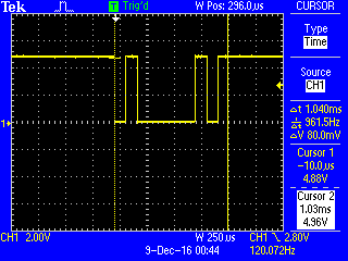
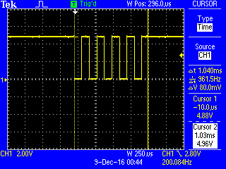
    The wafeforms below shows the character "A" (0x41) being transmitted at 9600 baud.

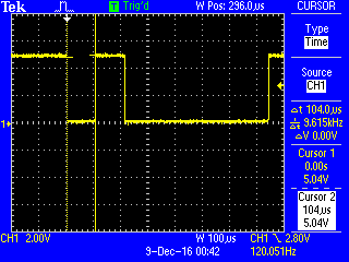
    The next waveform shows the character "U" (0x55) being transmitted.

    The second video shows the code being loaded from a binary file. An application test was written to read the memory locations where the code sits in and print them as hexadecimal values.

  • Cleanup and repository

    danjovic11/26/2016 at 15:12 0 comments

    I have made a cleanup in the code, eliminating the selection of the multiplex for PORTB which was useless for only writing to the joystick ports.

    Restructured (slightly) the code by moving the instructions that select PSG register to the subroutine where they are used. Now the structure of the program follows the diagram below.

View all 11 project logs

  • 1
    Step 1

    Loading the Hook Code

    In order to use Joy232 it is necessary to load it on the MSX by either of the methods presented below.

    Method 1:

    Copy the file "joy232.bin" to a floppy disk (or an equivalent option like the SD Mapper interface.

    load and execute the program by typing

    bload "joy232.bin",r

    It will install the hook code.

    Method 2:

    Type the following program:

    10 REM
    20 REM Joy232 hook code
    30 REM danjovic 2016
    40 REM
    50 EI=&HFAF5:SIZE=44
    60 FOR A = EI TO EI+SIZE
    70 READ B$: POKE A,VAL("&H"+B$)
    80 NEXT A
    90 REM
    100 POKE &HFFB8,&HFA
    110 POKE &HFFB7,&HF5
    120 POKE &HFFB6,&HC3
    130 REM
    140 DATA F3,F5,C5,E5,6F,3E,0F,D3
    150 DATA A0,26,FF,A7,CB,15,CB,14
    160 DATA 06,0B,DB,A2,CB,87,CB,1C
    170 DATA CB,1D,CE,00,D3,A1,0E,11
    180 DATA 0D,20,FD,10,ED,E1,C1,F1
    190 DATA A7,FB,33,33,C9

    Execute the program to install the hook code.

    run

    If you typed the code it is recommended to save it for future usage. It can be done by either:

    a) Saving the code to a floppy drive by typing

    save "joy232.bas"

    b) saving to cassete by typing

    csave "joy232.bas"

  • 2
    Step 2

    Testing the hook code:

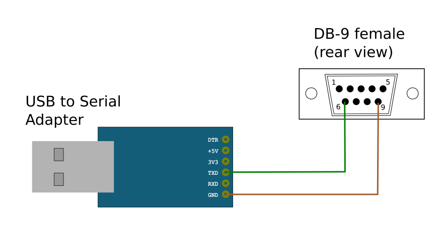
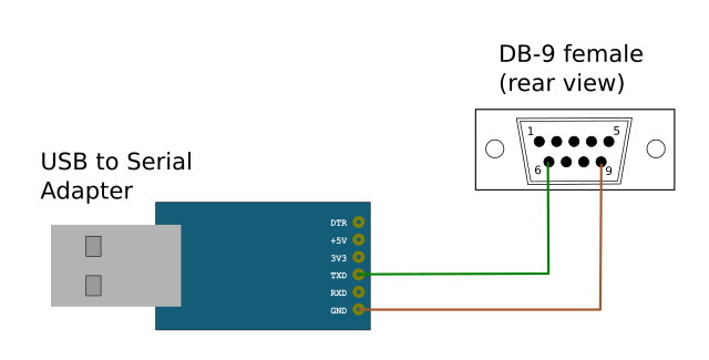
    First connect the USB to Serial interface to the PC and do the wiring to the DB-9 connector as follows:

    • Pin 9 from DB-9 to the GND of serial dongle
    • Pin 6 from DB-9 to the serial input line. The serial Dongle I am using name this pin as TXD

    Some serial dongls might have different pinouts and naming for the pins. The one I am using was wired as below:

    Then connect the DB-9 female to MSX joystick port 1.

    Then send something to the printer by simply typing any command which uses the printer, forinstance:

    lprint "Hello World"

View all instructions

Enjoy this project?

Share

Discussions

Similar Projects

Does this project spark your interest?

Become a member to follow this project and never miss any updates