-
1 year later update - flashback to original laptop mods
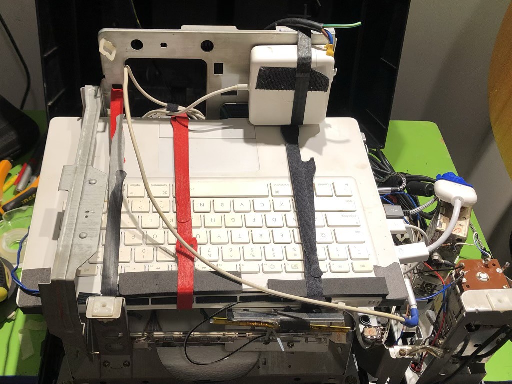
06/01/2023 at 17:03 • 0 commentsThe brains of this system is a Core 2 Duo MacBook from around 2007. I chose this because I had it, and it was well out of date for any current internet use. I installed the Lakka linux distro with Retroarch, and it works great. Its emulation capability seems on par with a Raspberry Pi 3, its performance is hampered a bit by using an older mechanical hard drive, but that mostly just impacts boot time
Because of the way this laptop is built, it was easier to include the entire body and keyboard instead of deconstructing it to only use what was needed.
![]()
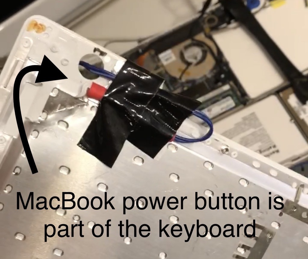
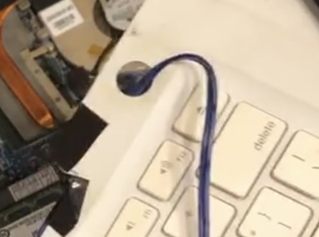
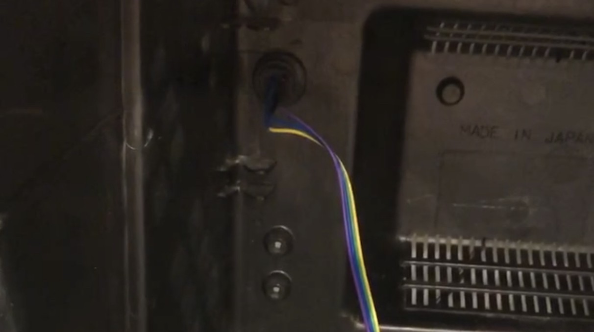
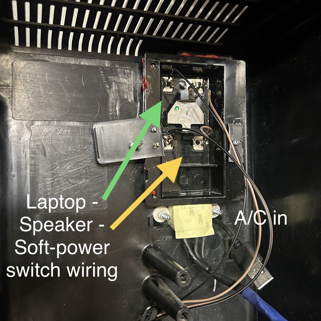
For instance, the power button is physically part of the keyboard, set between the top case plastic and a metal shield underneath. There is no power control on the motherboard itself. My solution was to peel back the metal shield and solder a wire to the power button contacts. This wire runs to the back of the case. It’s a bit janky, but it works.![]()
![]()
![]()
AC power is provided by the original Apple power supply charger, hardwired to a standard computer extension cable, and run under the chassis through the groove designed for that purpose. Another standard cable can be connected to the extension, but is mostly needed for charging, because despite the goal of frugality, one of the few things I purchased for the build was a replacement battery for the MacBook.
I have since made a slight modification to the power arrangement, which I’ll cover in another update.
-
1 year later update - Audio
05/31/2023 at 21:09 • 0 commentsIt’s apparently been a year since I updated this, and I recently made some changes. Here are the things I wanted to fix after using it for a while.
- Audio is 1) very soft, and 2) difficult to control. The only way to change the volume was shortcut keys in Retroarch, which was clunky and slow. It was also a big speaker powered by a regular headphone Jack, so it was just too quiet.
- Power. 1) the power button was in an awkward spot, and 2) the AC cable needed to be wrapped up in the back, which made connecting and disconnecting it from power more difficult.
- Authenticity. I want to try to incorporate more of the original parts in more useful ways.
- Additional interior lighting.
Here were my fixes. I have pictures in the gallery.Audio:
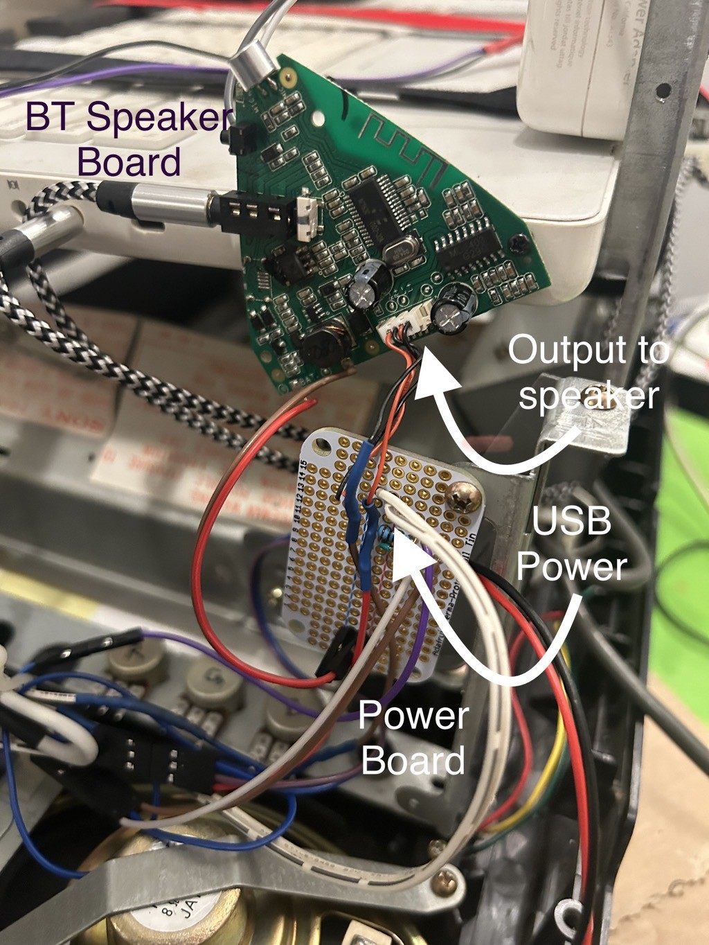
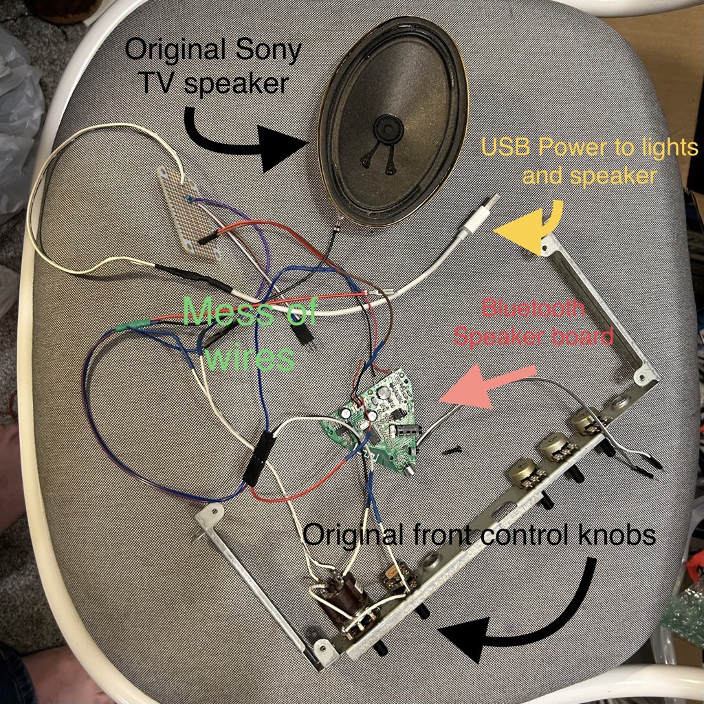
after trying a few other solutions for the loudness issue, I settled on using the circuit board from a Bluetooth speaker that had a bad battery. I was able to run it off the same 5v DC USB input as the front channel indicator lights, and it provided plenty of power for the original built-in speaker. I could have bought something, but that was outside the scope of the project.
![]()
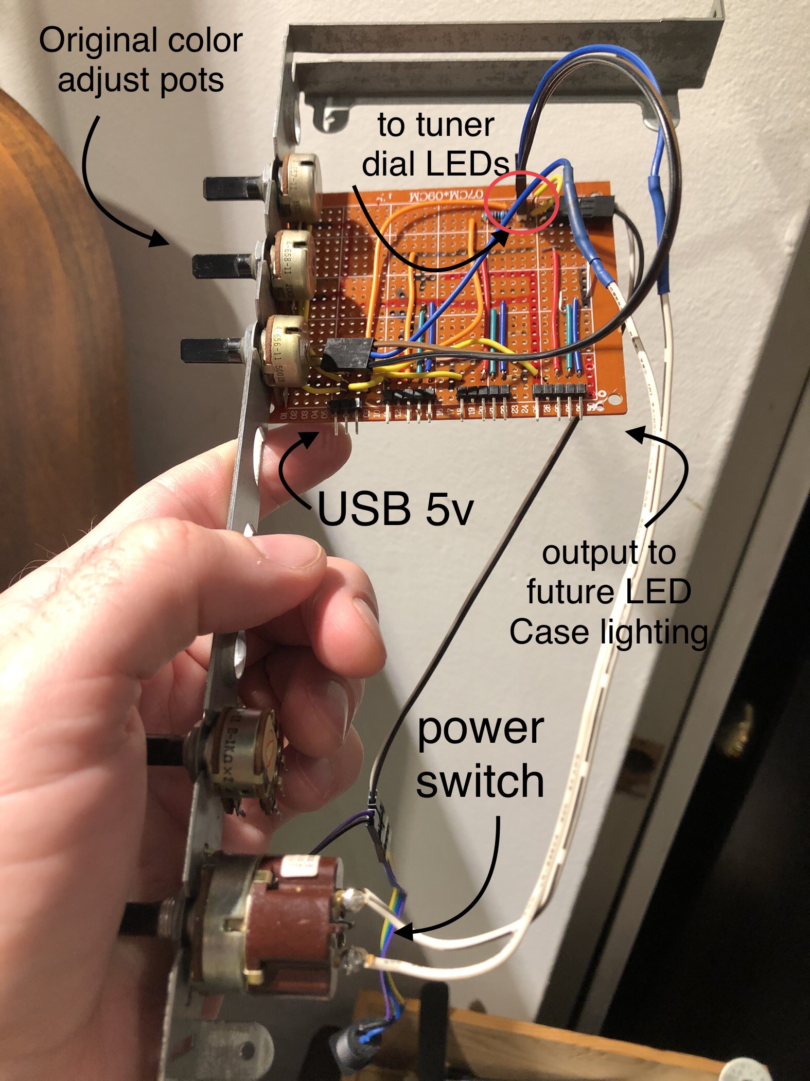
To control the audio, I ran the speaker ground through the original front volume pot. Fortunately, that unit had two separate switch circuits, so I was able to also run the audio through one of those so when I pushed off the power, the audio and front channel lights would turn off together. Very authentic to the original behavior. It’s a very satisfying effect.
I did run into some frustration with that volume pot apparently being linear instead of logarithmic. Meaning it was really twitchy and went from full volume to silent with very little movement. Oddly, and luckily, the “picture” knob right below it was much smoother for audio, so since I couldn’t think of anything else to do with that knob, I wired it in sequence as a fine tuning for the audio. It means I can keep the feeling of the original volume knob, but have a bit more control over the sound when needed.
![]()
the final audio bit was to run another wire to the back of the case for the Bluetooth speaker power. Like most modern electronics, it has a momentary soft-power button, so it needed to be controlled separately. This worked out to fit nicely with how I arranged the rear panel.![]()
-
USB Lighting - Part 1
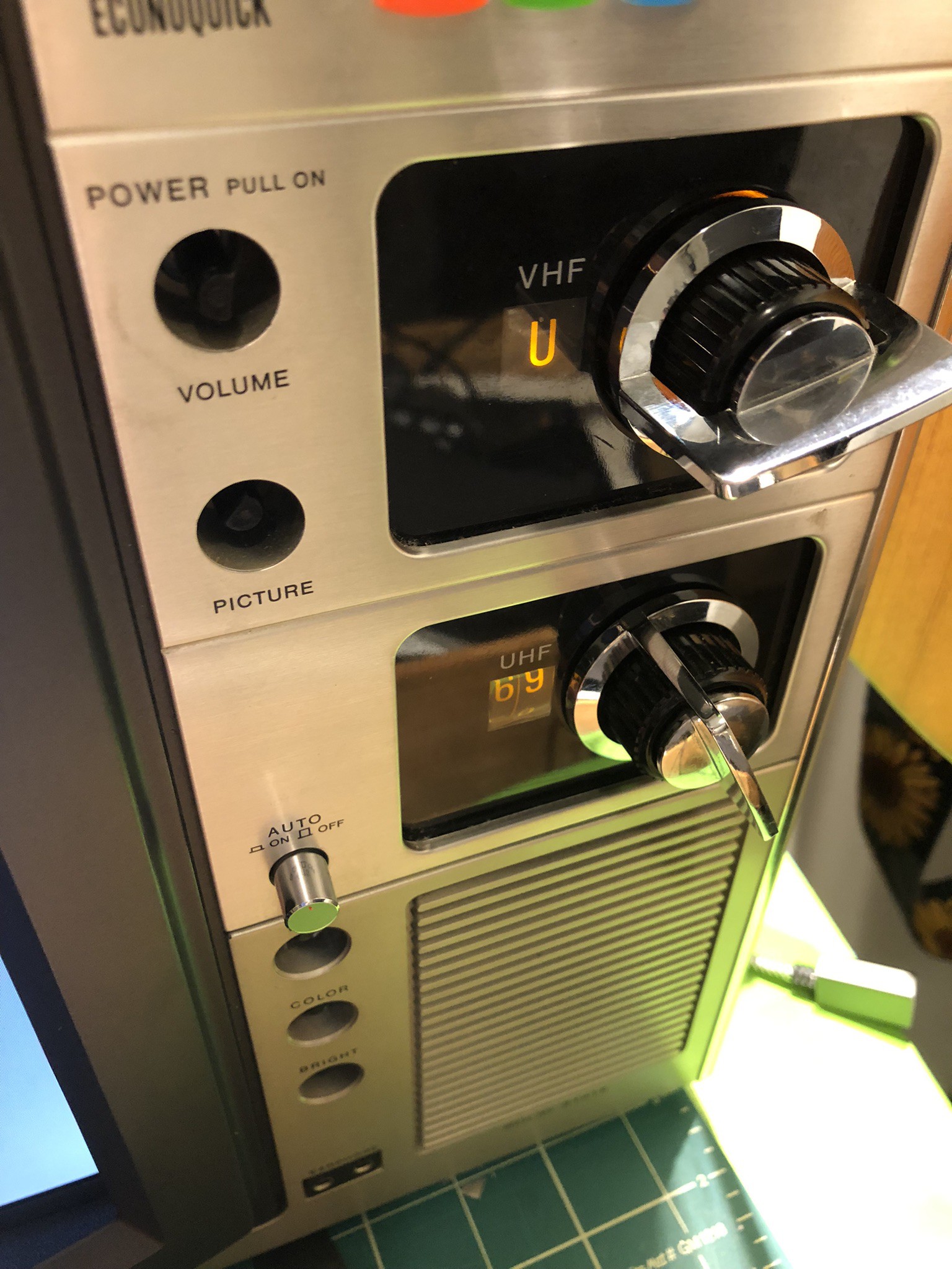
06/02/2022 at 15:30 • 0 commentsAside from being able to play games, I wanted to give the television an authentic appearance when it was powered on - which meant adding lights to the channel indicators. It was easy enough to do one, but I wanted to maintain the original behavior of the bottom UHF dial lighting up when the VHF channel was set to “U”.
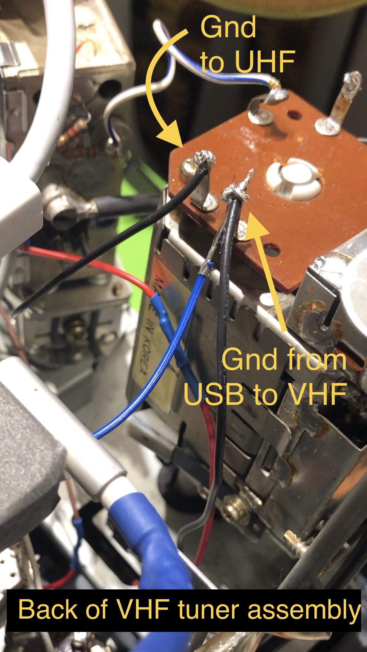
I had no idea how to do this, because the electromechanical tuners are a mass of gears and metal and wires and I have no idea what any of it does. Luckily, through trial and error, I discovered two contact posts toward the back of the VHF tuner assembly that showed continuity when on channel U, so I patched my ground wires through those posts for the LEDs.
![Back of vhf tuner assembly Back of vhf tuner assembly]()
Ground connections for tuner dial LEDs Once I knew it would work, I replaced the old bulbs with new yellow LEDs to match the translucent amber dials. I would love to keep the old bulbs, but they don’t seem to run 5v, so I’ll keep them and maybe try later. The last step was powering it, so I made a board to distribute 5v DC from a laptop USB port, with space to add other LEDs in the future. Finally, I wired in the original TV power switch to the dial lighting to mimic turning on and off the tv.
![Power board and front bracket Power board and front bracket]()
Power board and front panel control bracket I’ve installed the tuner assembly back in the front panel and it looks great!
![Tuner dials lit up Tuner dials lit up]()
Installed tuner dials with lights
Classic Recycled Emulation Box
Combining several pieces of my collection that are no longer useful on their own into a portable, all-in-one retro gaming machine
 Greg Does Things