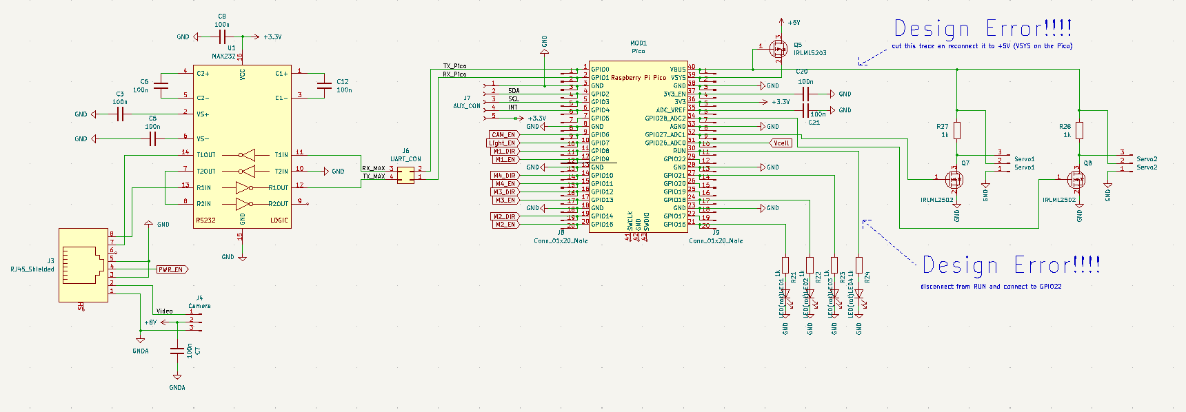
The schematic of the main electronics on the PCB can be seen here:

A RJ45 jack is used to connect the tether to the PCB. The TX and RX trace are connected through a MAX232 to a RPi Pico which controls everything. The Pico controls the thrusters through motor drivers (L293, not visible here) and two SG90 RC servo motors for turning the camera gimbal. Additionally a 4 LED debug light and an auxilary I2C bus are connected to the Pico and some day i might find an Application for that. Luckily i already ordered the pcb, so i dont have to fix the parts which are marked with "Design Error !!!!". Again, success!

The tether also carries a signal which controlles a PMOS FET to disconnect the battery so i can turn the hole thing on and off without disassembling it. Additionally there is a voltage divider to reduce the battery voltage by roughly a factor of 5 and feed it to the adc of the Pico. If it gets too low i will probably do something with that information.
+5V power is provided by the finest LM7805 my junk bin could offer.
The video signal is generated by an RC FPV camera. Signal and separate video-gnd go through the tether as well. The +8V power for the camera is provided by a separate LM7808 to completely separate the noisy digital- and servo-supply from the camera supply. The camera supply can be turned on and off because the camera eats a lot of power and should be turned off when ever it is not in use.
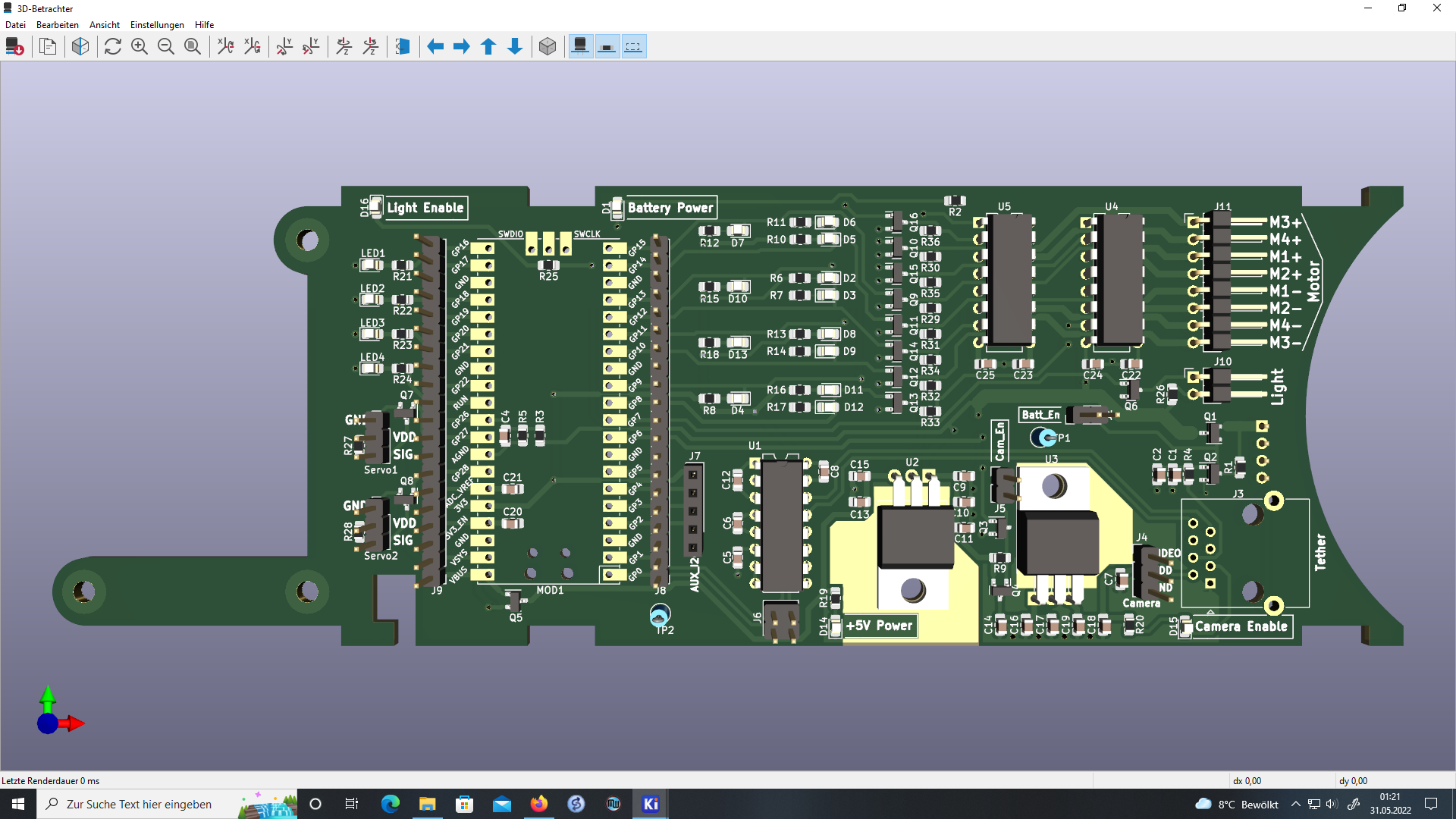
This is how the render of the PCB looks like:

 Timo
Timo
Discussions
Become a Hackaday.io Member
Create an account to leave a comment. Already have an account? Log In.