Peter Walsh
-
More motor survey
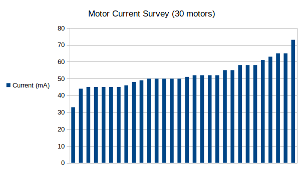
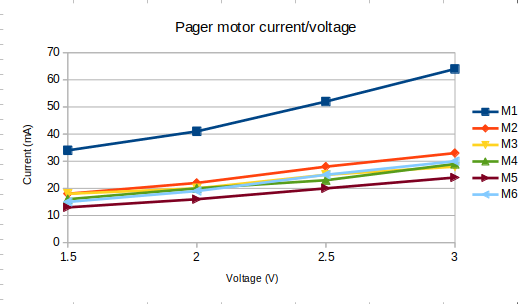
06/16/2022 at 14:23 • 0 commentsI got 30 more motors, and did another motor survey of current requirements. The results are below, the chart shows the current draw of 30 motors run at 3.0 Volts:
![]()
Key takeaways:
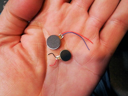
1) The new batch draws roughly 50 mA (each), which is more in line with datasheet specs, as opposed to the previous batch of motors which drew 30 mA. The new batch is also smaller (8mm dia, instead to 10mm), and has short leads.
2) Coin cell motors with short leads are more difficult to manage. Quite possibly these will not easily mate to a flex-PCB due to the short leads.
3) The current measuring jig works pretty well.
![]()
The right answer is probably to order high-quality motors from reputable sources, rather than eBay bargain basement units. The price for eBay units is about $0.30 each, while the DigiKey price is around $2.50 each (qty: 10).
For the near term (ie - development), it makes better sense to order a pile of cheap motors from eBay, then check the current draw and toss the one or two that are wildly out of spec.
A hypothetical product with 6 (one strip) or 12 (two strips) motors would require $15 or $30 for the motors alone.
Another right answer is probably to use a fixed-current driver for the motors. The TLC5917 is an LED driver, but the PWM outputs should work well for the motors. Current limit up to 130 mA set from a single resistor, and PWM managed by the chip itself. Price: $1.50 each (qty: 10).
-
Clothespin Measurement Jig
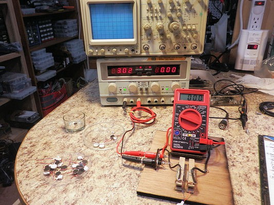
06/15/2022 at 23:36 • 0 commentsMeasuring the current draw from pager motors physically difficult, and I wanted to do another "motor survey" to get a handle on the current draw, so I decided to build a jig for easy measurement.
Now I'm perfectly aware that power supplies will show both voltage and current, but display isn't the issue: making contact with tiny wires is the problem.
After some brainstorming, I decided that a thick gauge wire wrapped across the top jaw of a clothespin, pinching the wire against a flat piece of PCB would provide a good contact for short lengths of tinned wire ends.
![]()
The system uses an embedded DVM to show the current. Harbor Freight was giving these away for free, and I managed to snag some to embed into projects. You can get them for about $5 on eBay, with free shipping.
In practice, you set your power supply to the voltage you need, then either:
- Open the clothespins, and close them on the tinned ends of the wires
- Touch the tinned ends of wires to where the two landing pads
- Slide the wires along the landing pads, until they get pinched between the pad and thick wire.
In practice, the last 2 methods proved the most convenient.
Materials needed
- Cheap DVM
- One pair of terminal posts
- Two clothespins
- Short length of thick wire (such as 14 gauge)
- Stiff cardboard, or 1/8" plywood
- 4 button feet
- A tiny piece of copper-clad PCB
Tools needed
- Laser cutter
- Hot glue gun
Construction
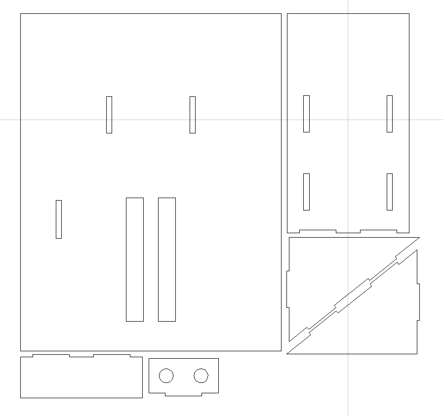
(NOTE: The design files are available either in the project main page, or on GitHub referenced from the main page.)
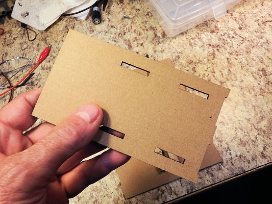
The cardboard is assembled using "slot and tab", with hot glue to hold everything together.
![]()
The jig can be made from 1/8" plywood, but it actually works quite well when cut from stiff cardboard. I made my actual device with 1/4" wood as a base, and used the cardboard pieces for everything else.
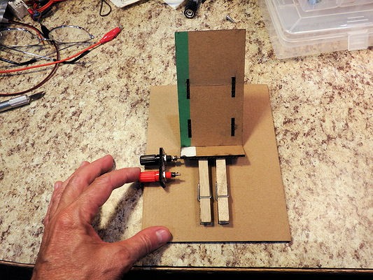
![]()
A quick demo test of the original design. Hmmm... the DVM holder should be moved back a bit. Update the design.
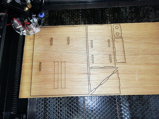
![]()
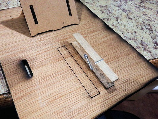
Cut the wooden sections.
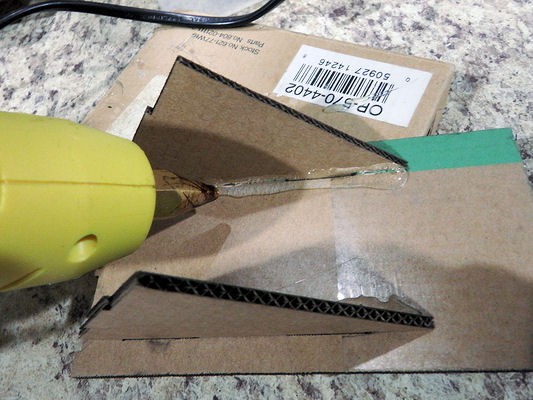
![]()
And glue the pieces together.
I realize that you can make pieces that snap together in various ways, but doing that requires you to dial-in your laser cutter for a snug fit, and a lot of people don't do that or don't know how to so that.
Essentially, "snap together" joins are fine if you're making many dozens of copies, as for a product, because you can tune your design to the exact thickness of material.
For a one-off jig, hot glue and large, easy-to-assemble slots is much easier.![]()
The base has an etched pattern (not holes) to indicate where the clothespins go.
![]()
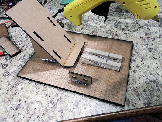
Hot glue the clothespins into position.
![]()
Gluing complete.
![]()
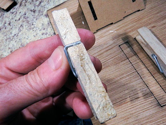
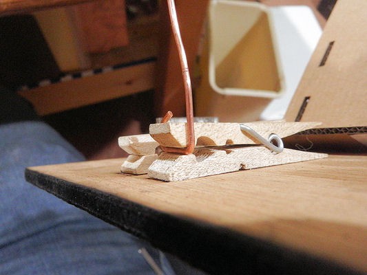
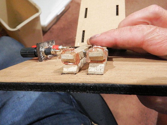
Take a piece of thick wire, such as 14 gauge (a short length of stripped Romex works well) and bend it around the end of the clothespin as shown.
This will make a rounded, cylindrical contact with the landing plate. A wire placed in the jaws of the clothespin will be pinched against the wire and the landing plate, making a good contact.
![]()
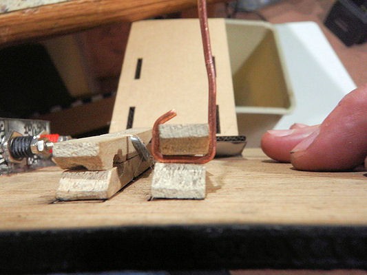
Side view of the wire contact.
![]()
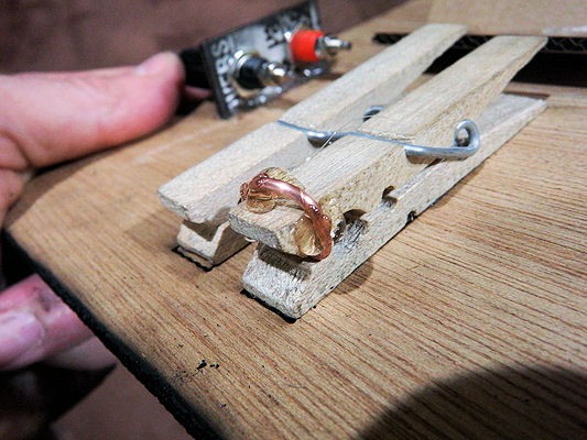
Trim and complete the wire contact as shown. Note that one side of the wire higher than the top of the clothespin, leaving an underpass. A connection can be threaded through the underpass, and soldered.
![]()
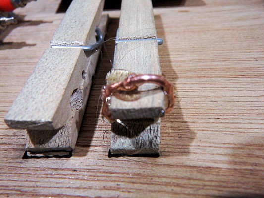
Glue the wire contact in place.
![]()
Side view of glued contact. Looks messy, eh?
![]()
Completed wire contacts, glued into place. Looks *really* messy, but that's OK!
![]()
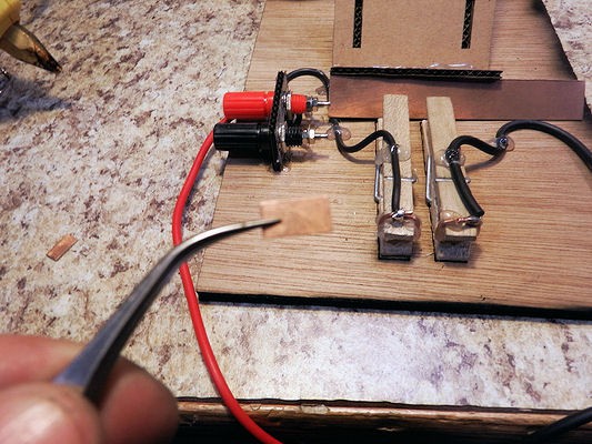
Connect everything together. Red post -> Ammeter -> Right clothespin. Left clothespin -> Black post
Hmmm...
1) The posts extend beyond the edge of the board, and
2) The post connections are unshielded (from your hand, for example) which might be a problem if the device is used for other (ie - high voltage) purposes.
FIXED: The new design moves the terminal posts to the UL corner, where they are out of the way, and inset sufficient so that they don't stick out.
![]()
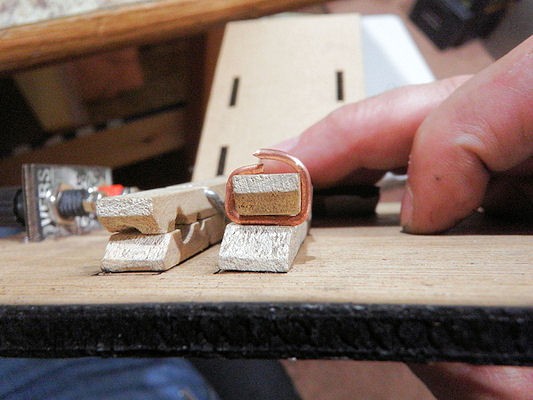
Cut a small piece of PCB to act as landing pad for the wire electrodes. The piece should be as wide as the closepin jaw, and 3x or 4x the the thickness of the wire.
![]()
Coat the back of the landing pad with glue, place onto the bottom of the jaw, and allow the wire to press against the landing pad until the glue cools.
This looks misaligned, but that's because the wire is misaligned and probably not straight, due to bending. The pressure from the clothespin actually aligns the landing pad with the wire, making a snug fit.
![]()
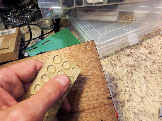
Add a few button feet to the back. This gives a nicer feel to the device, and keeps it sliding around if you need to manhandle something into the jig.
![]()
Here's the finished jig. I'm using hot glue to dress the wires, because it's rapid development and I can't be bothered with doing it the right way...
![]()
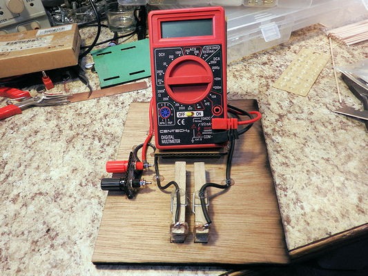
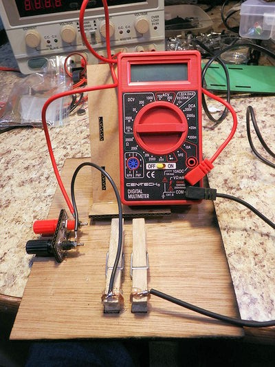
And here's the device, setup and ready for the motor survey.
![]()
-
Haptic Drivers
06/04/2022 at 00:39 • 0 commentsBench testing is going okay, but I need a better, and safer way to drive the array of haptic devices. I had some level shifters at my work bench, and they get me going, but they aren't the correct thing for the job. The successfully isolated the current draw, but they do nothing to isolate the motor noise and inductance kick when they stop. Part of the problem is the level shifters I have are bi-directional.
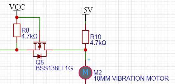
The level shifter looks a bit like this:
Signal in from the left, to the positive on the motor.
![]()
BSS138LT1 - Power MOSFET, 200 mA, 50 V, N-Channel SOT-23 (onsemi.com)
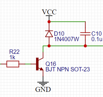
A more traditional motor driver looks like this:
Once again, the signal comes in from the left, but in this case it is sinking the ground from the motor. The motor has constant power, and the ground access passes through a NPN BJT like a 2N2222. Additionally there is a diode for spike management and a capacitor for noise management.
![]()
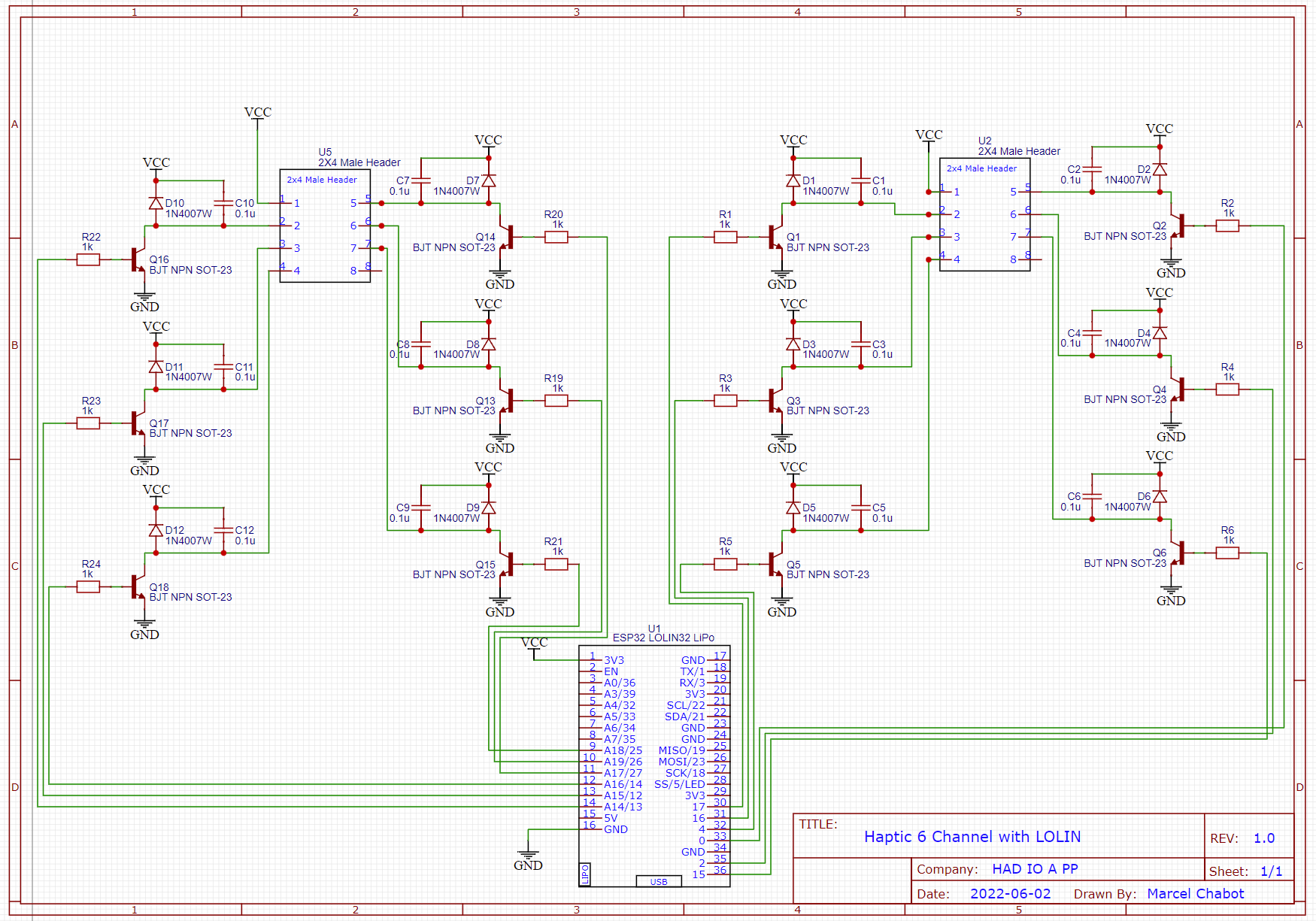
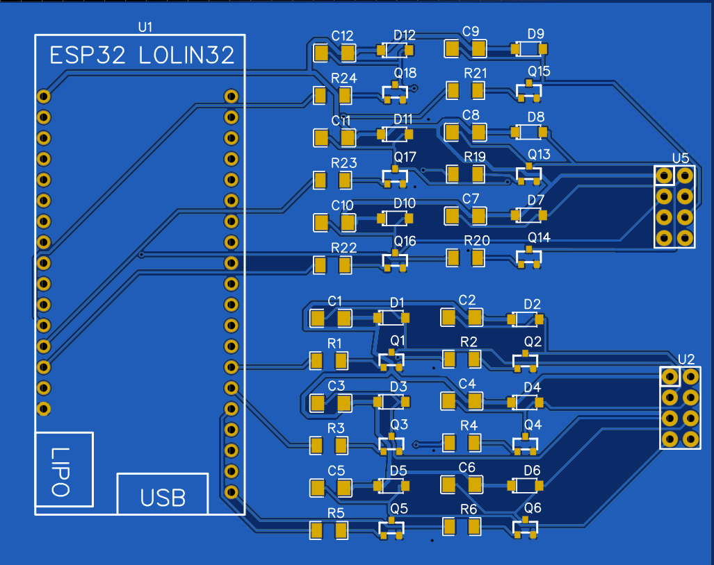
The goal is to drive quite a few, so we can start with 12.
![]()
I'm just learning EDA, so I'm sure there are a lot of things a seasoned professional would do differently.
Get everyone out on a PCB all nice and neat and we get something like this:
![]()
This board should allow us to drive 12 haptics, on 2 banks of 6.
This is draft one, I'm going to think about it for a bit before committing to having it prototyped. I should breadboard out a few of the drivers and double check their performance.
-
A look at skin stimulus resolution
06/02/2022 at 16:15 • 0 commentsWhen I was in school (when tiny dinosaurs ruled the Earth) we did an experiment to map nerve endings on the skin. We had someone remove their shirt and lie down on a table, then we took 2 toothpicks and pressed against the skin of the back and asked whether it's 1 toothpick or 2.
When the toothpicks are close together, they activate a single neuron, which the subject reports as a single point. Moving the points further apart, eventually the 2nd toothpick activates a 2nd neuron, and the subject reports feeling 2 points. That's the boundary between the (sensation area of the) neuron of the 1st toothpick and another neuron.
Using this method and a pen, you can draw a map of the areas sensed by single neurons on the back, and various parts of the body. IIRC, the map of the back had rather large (1.5" wide) blotches, so that my back of 14" by 12" would be sensed by about 75 neurons, more or less. A matrix of roughly 8 x 9 neurons reports touch sensation on the back.
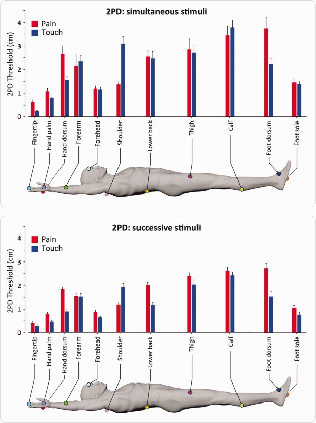
So I took a look at the literature today, and sure enough someone mapped of the entire body using this method. Below are relevant results (from that study).
Using the successive stimuli graph (due to motor motion), the theoretical resolution of touch sensors on the skin (the width of the neuron sensing area) is about 1.5cm for the forearm, 2.5cm for the calf, and 1.5cm for the belly (using the numbers for the lower back).
The motors themselves are 10mm discs. It seems that having motors close together will probably not give the wearer a greater sense of resolution, when used on the forearm, calf, or belly.
![]()
Source: Mancini F, Bauleo A, Cole J, et al. Whole-body mapping of spatial acuity for pain and touch. Ann Neurol. 2014;75(6):917-924. doi:10.1002/ana.24179
-
Oh, What a Feeling!
06/02/2022 at 02:45 • 0 commentsWith the duct tape prototype in hand, it was time to activate the haptic devices and see what sensation we could work with. I had used the LOLIN32 boards for several WS2811 based lighting projects and had a few with headers installed and ready for the breadboard.
The ESP-WROOM 32 on the LOLIN board can only provide about 12mA max per pin, and should be limited to 9mA, which falls below the results of the current survey. I added a series of 3.3v to 5v level shifters to the circuit to manage the per pin current as well as step up the voltage for better activation of the devices.

Breadboard Proto 1 As the spacing of the haptic devices is more or less arbitrary, I decided to generate both a single device progressive, single device random and wave pattern to get a feeling of what kind of feedback these devices can generate. I strapped the device to the inside of my forearm and began sending the signals.
Each device is driven with a PWM signal from the LOLIN32, with a range of 0-255.
Running each individually at 125 for 5 seconds each I am able to notice the progression up the device. Now things got interesting, with the exception of Device 1 and 6 on the edges, when activated randomly the best I could identify was a low (device 2/3), middle (device 3/4), and upper (device 4/5) sections.
I generated a wave pattern from 0 to 255 and back to 0, with each device being 42 steps out of phase with the previous device. This created a rolling triangle wave up the devices. While running this pattern I could not identify the location of the wave at all. I made several attempts at adjusting the speed of the wave but once all the devices were active, I could not distinguish any real pattern.
The lack of data clarity may be due to several factors. One factor may be due to the vibrations propagating through the duct tape structure. Another factor may be with the sensory capabilities of the inside of the forearm, it isn't an area with an abundance of touch receptors, resulting in a lower fidelity. The last factor may be a lack of familiarity with data input from that region of the body.
-
Vibration Motor current survey
06/01/2022 at 19:24 • 0 commentsAfter building the 2nd prototype I took the opportunity to do a survey of motor current. The results are shown below.
Most of the motors run in the 20 mA to 30mA range, depending on voltage, with one outlier.
I *assumed* that the outlier was due to grabbing a pack of cheap reject motors off of eBay, but looking at actual pager motor specs on Mouser shows that most motors are spec'd to run in the 70-90 mA range, depending on motor type.
I have to check another couple of packets of eBay motors to see what the typical current draw is.
This bears on the electronics design, as to whether we can drive the motors directly from the micro GPIO outputs, or will need driver chips.
![]()
-
First proto board made
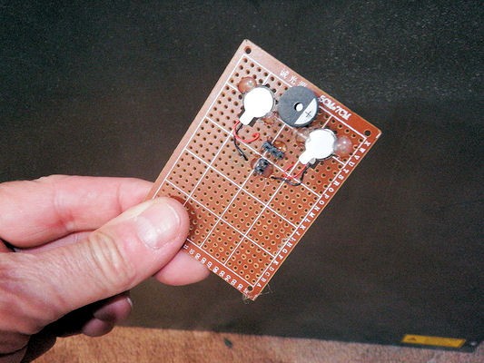
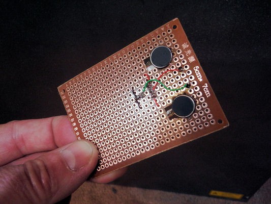
05/31/2022 at 19:25 • 0 commentsMade a quick proto board to give to the software/micro guy to play with.
Two motors on a small proto board, with an alerter. The alerter was an afterthought, and mostly because I had a bunch of them sitting around unused. I figure the alerter can be used in conjunction with the haptic feedback as an alert - when the ammo (or health) gets below a certain value, the alerter will beep. When the health gets critical, the beeper will beep continuously, and so on.
The user can easily distinguish an alert coming from their forearm instead of the computer, so this should add to the haptic experience.
Note: Laser cutter goes through perfboard very well.
![]()
![]()