Upkie wheeled bipeds
-
Model predictive control on Upkies
12/13/2024 at 09:15 • 0 commentsHere is an Upkie wheeled biped roaming outdoors by model predictive control:
It goes around with an average velocity around 1.5 m/s. There are some links in the video to learn more about how this agent is made:
- Open loop and closed loop model predictive control
- Model predictive control agent
- Wheeled inverted pendulum model
- ProxSuite library with the ProxQP solver
- Awesome Open Source Robots
The agent running in this video is the Pink balancer. It combines MPC and differential IK for crouching smoothly. Hoping this helps newcomers get started with model predictive control!
-
Reinforcement learning on Upkies
12/09/2023 at 15:53 • 0 commentsThe latest release of Upkie's software brings a functional reinforcement learning pipeline with sim-to-real transfer. The pipeline is based on Stable Baselines3, with standard sim-to-real tricks that could very well work on other wheeled biped robots. The pipeline trains on the Gymnasium environments in
upkie.envs(pip-installable from PyPI) and is implemented in the PPO balancer. Here is a policy trained in Bullet and running on a real Upkie:There is also a usage video showing how to run the pipeline:
Hoping this helps newcomers get started with reinforcement learning on real robots!
-
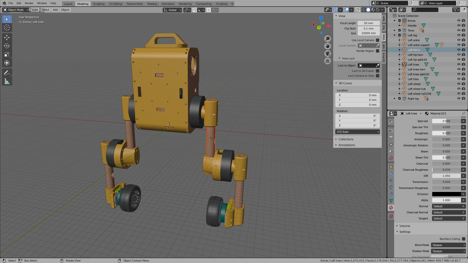
Blender project
11/12/2023 at 10:36 • 0 commentsWhile the build manual and parts CAD files help, they don't make a full specification and there are always some blind spots when assembling a new Upkie for the first time. To help cover more ground, there is now a Blender project file showing how all parts fit together:
![]()
The project does not detail every screw, but it can help double check and answer questions such as "where does the battery connector fit behind the face plate?" :) An overview STL file is also available if you just want to have a quick look at the assembly. Hoping this helps!
-
Hollow leg, part 2
10/03/2023 at 09:26 • 0 commentsThis project log follows up to Hollow leg, part 1, where we redesigned Upkie's femur to route cables through. We now do the same for the tibia.
Our goals are the same:
- Ensure that cables don't collide with the limb during motion.
- Keep a large range of motion for knee joint.
Again, we switch to 3D printing for the tibia part, with a cable guiding hole going through it. The part is identical to the femur, but the heat-set insert holes are both on the same side this time:
![]()
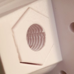
The ankle socket is redesigned as well with an hexagonal shape to better transmit torques:
![]()
We also switched to cable sleeves rather than corrugated plastic tubing, as they slide more smoothly and bend less awkwardly:
![]()
Assembled, the completed hollow leg looks like this:
Let's see how this new leg fares on real robots! Details to build and assemble it are further documented in Upkie's build instructions.
-
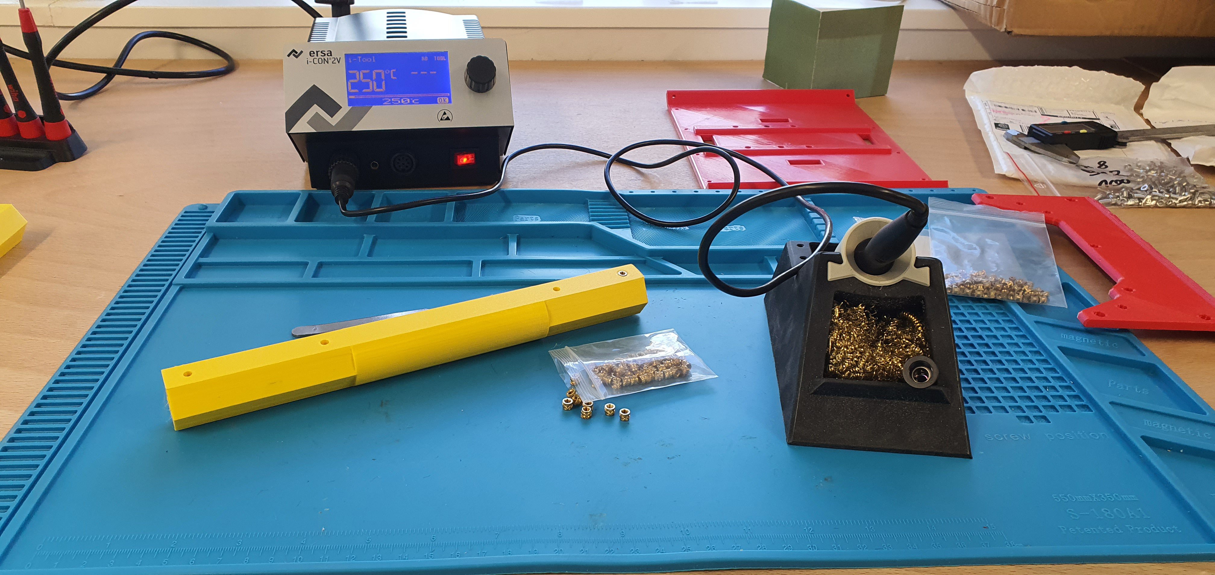
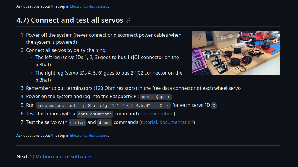
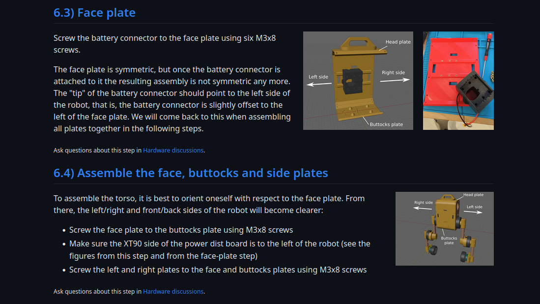
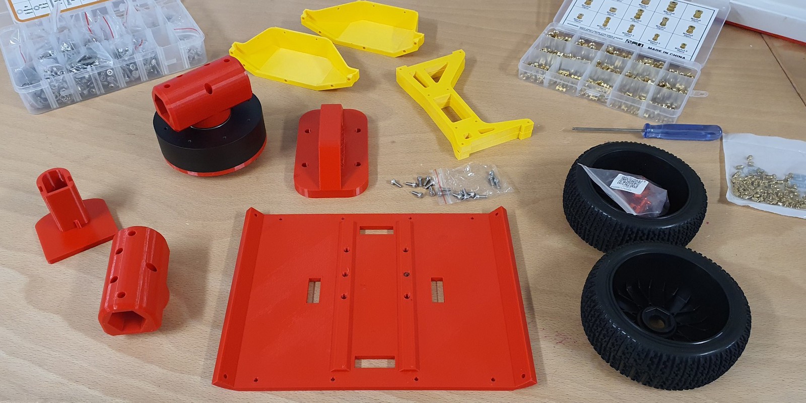
Build instructions for new Upkie's
09/27/2023 at 19:26 • 0 commentsWhile building new copies of Upkie, we wrote full Build instructions for future travelers. These instructions cover all the steps from ordering to running a first balancing experiment:
They go through intermediate stages like electronics assembly:
With figures, so that new comers know (and old timers remember 😉) the orientation of each part:
In the hope these instructions help spawn and maintain many Upkie's!
-
On GitHub: How to build Upkie from scratch?
04/01/2023 at 13:52 • 0 commentsBuild instructions on Hackaday.io work well for the outline, but as more copies of Upkie get built we wanted something that could scale nicely to include sub-steps, distribute related project files (3D printed parts, setup scripts, ...), and allow for discussions related to any given step.
Introducing the upkie repository!
- Instructions will be detailed step by step in the Wiki
- Discussions allow anyone to comment/ask questions on any given step
- 3D printing files and setup scripts are distributed in the companion build instructions
The wiki will be completed as we assemble another copy of the beast:
![]()
Stay tuned!
-
Locomotion with a PS4 controller
11/13/2022 at 16:56 • 0 commentsUpkie communicates with a regular PS4 controller. While this is not a key robotic feature, it is both cool (especially with kids 😃) and convenient to control the robot via Bluetooth. Before trying it out I was concerned about potential lags, or the Raspberry Pi loosing its connection to the controller, but the field summary after using it for months is: it just works. Here are my configuration notes, turned project log 😉
The setup instructions are not specific to Upkie: we can connect a PS4 controller to any Raspberry Pi. Start with the Bluetooh command line:
sudo bluetoothctl
Enable the agent with the following four instructions:
agent on
discoverable on
pairable on
default-agent
Then start scanning for devices. The terminal should start listing scan results with all the Bluetooth devices around you:
scan on
While the command tool is scanning, press and hold both the Share and PS buttons on your controller to switch it to pairing mode. Keep holding the buttons at the same time until it starts flashing white light. When it does, check the terminal output for a new line like this one:
[NEW] Device AC:FD:93:14:25:D3 Wireless Controller
Note down the controller MAC address (here
AC:FD:93:14:25:D3). Check that the controller is still flashing and do:connect CONTROLLER_MAC_ADDRESS
That should be it! If everything went well, you should see a "successful connection" message appear in the terminal, like so:
[bluetooth]# connect AC:FD:93:FD:68:0F
Attempting to connect to AC:FD:93:FD:68:0F
[CHG] Device AC:FD:93:FD:68:0F Connected: yes
[CHG] Device AC:FD:93:FD:68:0F UUIDs: 00001124-0000-1000-8000-00805f9b34fb
[CHG] Device AC:FD:93:FD:68:0F UUIDs: 00001200-0000-1000-8000-00805f9b34fb
[CHG] Device AC:FD:93:FD:68:0F ServicesResolved: yes
[CHG] Device AC:FD:93:FD:68:0F Paired: yes
Connection successful
Finally, trust the controller so that it can connect after a reboot:
[bluetooth]# trust AC:FD:93:FD:68:0F
That's it! The controller should now appear as a regular Linux joystick device in
/dev/input/js*. That's where the Joystick source in Vulp (Upkie's motion control software) will look for it. If it doesn't, perhaps you are running into the same reconnection issue I faced. Some follow-up troubleshooting notes in this discussion thread. -
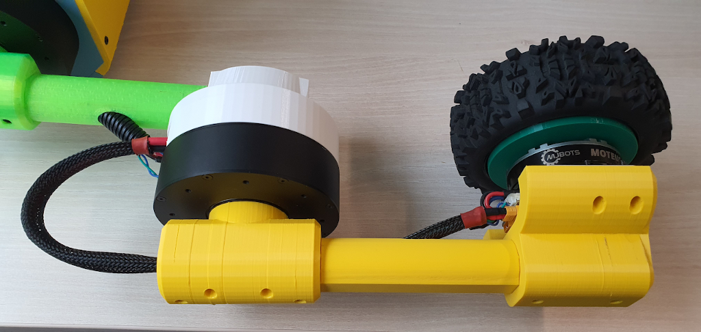
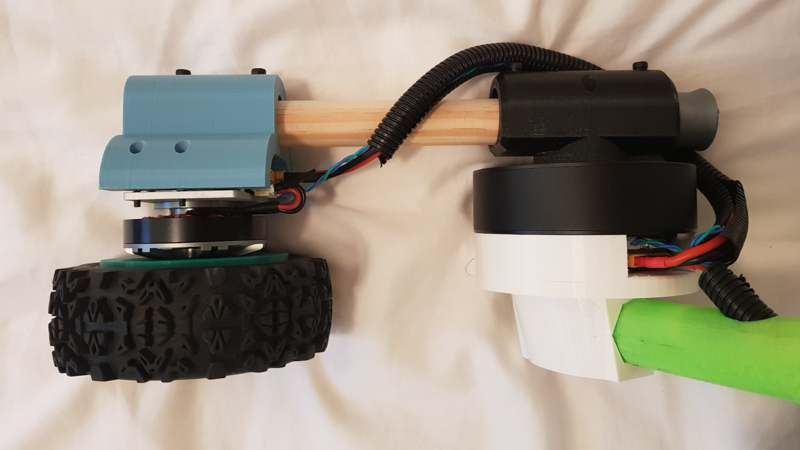
Hollow leg, part 1
08/10/2022 at 16:18 • 0 commentsSawing broomsticks to get Upkie up and running quickly was great at the beginning of the project, but it came with a drawback that came to light while manipulating the robot: a cable can get on the wrong side of a leg and get snapped away if the human manipulating it is not paying attention. Here is a bad instance on a shin:
![]()
Pulling a cable hasn't happened yet while balancing, as the corrugated pipes that hold power and communication cables are quite stiff by themselves and tend to stay away from the legs, but it has happened for sure while sitting and raising the beast. So, today's update is about routing cables inside the legs. (This is part 1, we'll see about the lower leg in part 2.)
Our goals are:
- Ensure that cables don't collide with the limbs during motion.
- Keep the same range of motion for hip joints.
The idea is to 3D print a cable guide inside the hip, femur and knee parts. The femur thus becomes 3D printed (bye wood 😢).
Here is a short video summary of the update:
More details on the successive iterations:
- Hollow cylinder: this was a first guess. It would have worked with pressure screws like before, but then it occurred to me that squares and hexagons are much better shapes to transmit torque. (See for example this video from Scilabus on screw heads.)
- Hexagonal femur: testing torque transmission on mock parts with an outer hexagon and inner cylindrical cavity. To get a nice fit when assembling 3D printed parts, we can set either the femur outer diameter or hip inner diameter to be slightly smaller/larger.
- Hip with a hollow hexagon: going for a slightly larger hip inner diameter with a +0.2 mm margin on each edge. One mistake I did was to test the fit with small chunks of the inner shape, which may go through whereas the complete part won't (due to friction or jamming). Better print the whole (or at least a reasonable chunk of the) part to test this.
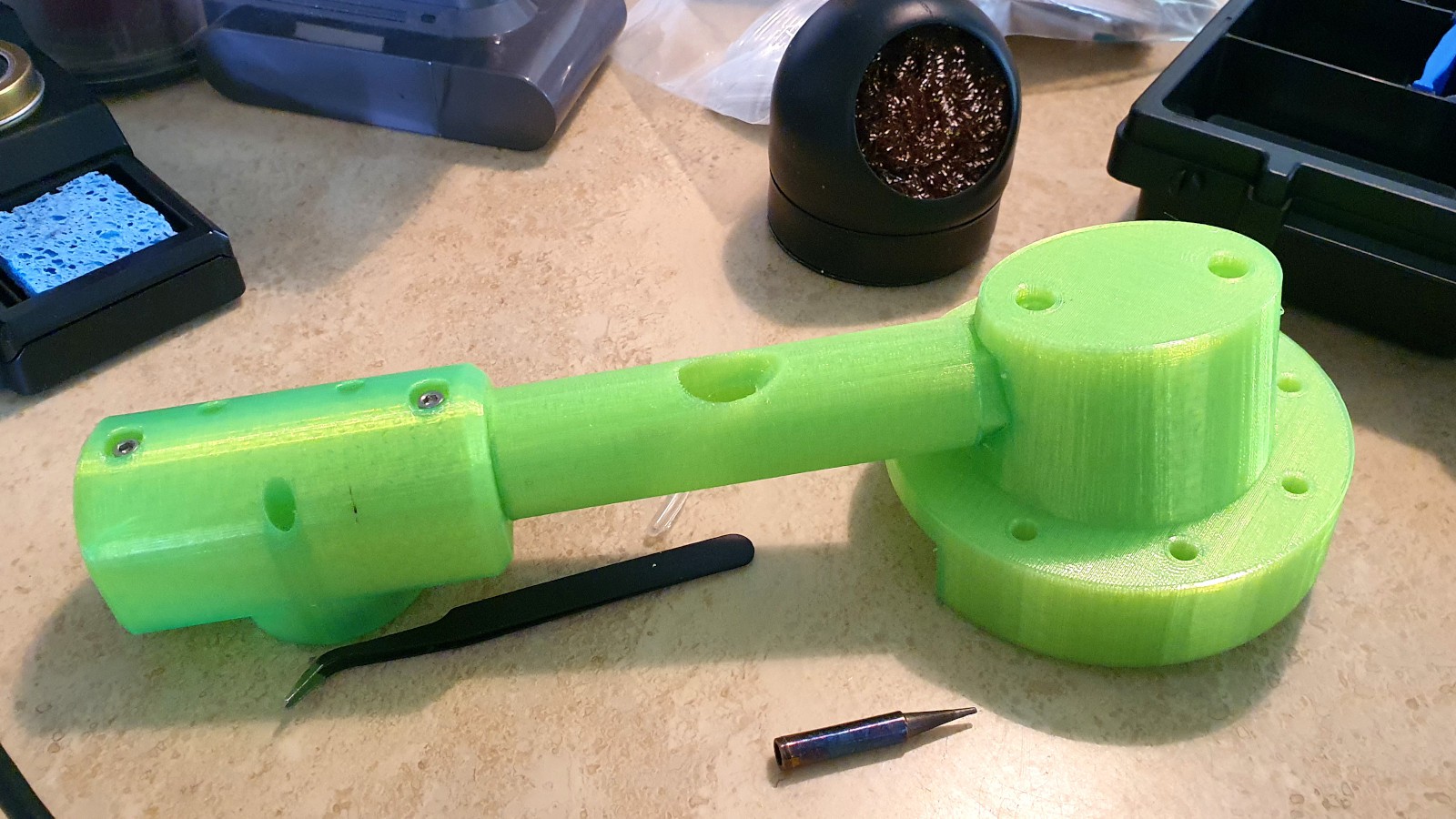
- Cylindrical femur with hex ends: the hexagonal shapes on both femur ends are exactly the right length to match the hips, and the femur is otherwise cylindrical. This facilitate assembly. Also, the inner cylinder guides the cable out the middle of the part to meet the knee servo connectors.
- Fixes to the hip: 3D printing iteration, getting all dimensions just right.
- Knee with a hollow inner hexagon: adapting the knee stator, following the same approach as the hip.
At this stage, the leg assembly looks like this:
![]()
One further nice thing to add are small rivulets inside the hollow cable guides to hold the corrugated pipe in place during motion:
![]()
There are still several questions on the table that this design does not answer. How about turning the knee servo 180° to avoid the cable outlet in the middle of the femur? Also, can we get corrugated pipe that bends more smoothly?
![]()
Note that we are keeping some length of cable above the hips to maintain the range of motion of the hip joint, in particular so that the robot can sit down and up properly. Eventually we can redesign the side chassis plates (blue in the picture above) to hold the cable better with a hole of the matching size (as opposed to a wide rectangular hole right now).
Those points are left to future work 👷
-
Blowing off some CPU steam
06/11/2022 at 20:07 • 0 commentsWhen running the Pink balancer agent on Upkie, the four CPU cores of the Raspberry Pi are used as follows:
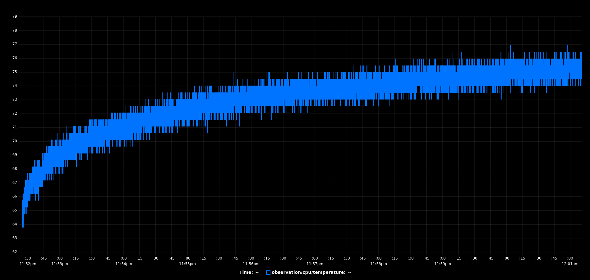
CPUID Processes Threads Usage (%) 0 Spine (+ other system processes) Logger (+ other system threads) 10 ± 5 1 Spine Spine loop 10 ± 5 2 Spine CAN communications 50 ± 20 3 Agent Python threads 100 On average over all cores, the ARM processor is only used at about 50% of its capacity, but that (or the fact that one core is used at 100% all the time) is enough to drive the CPU temperature up to a problematic level:
![]()
(If you were wondering why Vulp has a CPU temperature observer, now you now 😉) The issue is that to protect itself the Raspberry Pi throttles all computations if its CPU temperature hits 80 °C, which for Upkie results mostly in skipped control frames (wheels apply their commanded velocities for too long ⇒ balancing degrades) and in the worst case triggers Vulp's safety of stopping actuators when no action is sent for more than 100 ms.
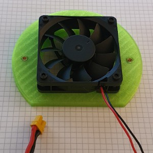
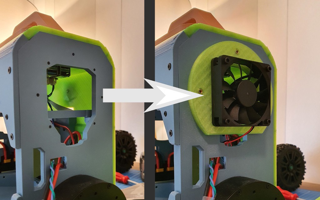
Luckily it's not hard to cool down a Pi. Having a standing fan blow air at Upkie from the sides, where its wide "seal ears" are, does the job just fine. But the robot is not designed to stay near a fan, so let's give him an "earpiece" so that it carries its own fan:
![]()
There is already a second male XT-30 connector on the pi3hat in Upkie's head, so we can order a 24 V DC fan from online retail, solder a female XT-30 connector to it, and just plug it to the power bus. In this update, the fan has the following properties:
- Dimensions: 60x60x15 mm
- Speed: 4700 rpm
- Noise: 32 dBA
- Power: 1.8 W
- Flow: 44 m³/h
The mount is a temporary adapter to connect to the existing right plate. Once we have settled on fan dimensions, we can redesign the plate so that it plugs into it directly:
![]()
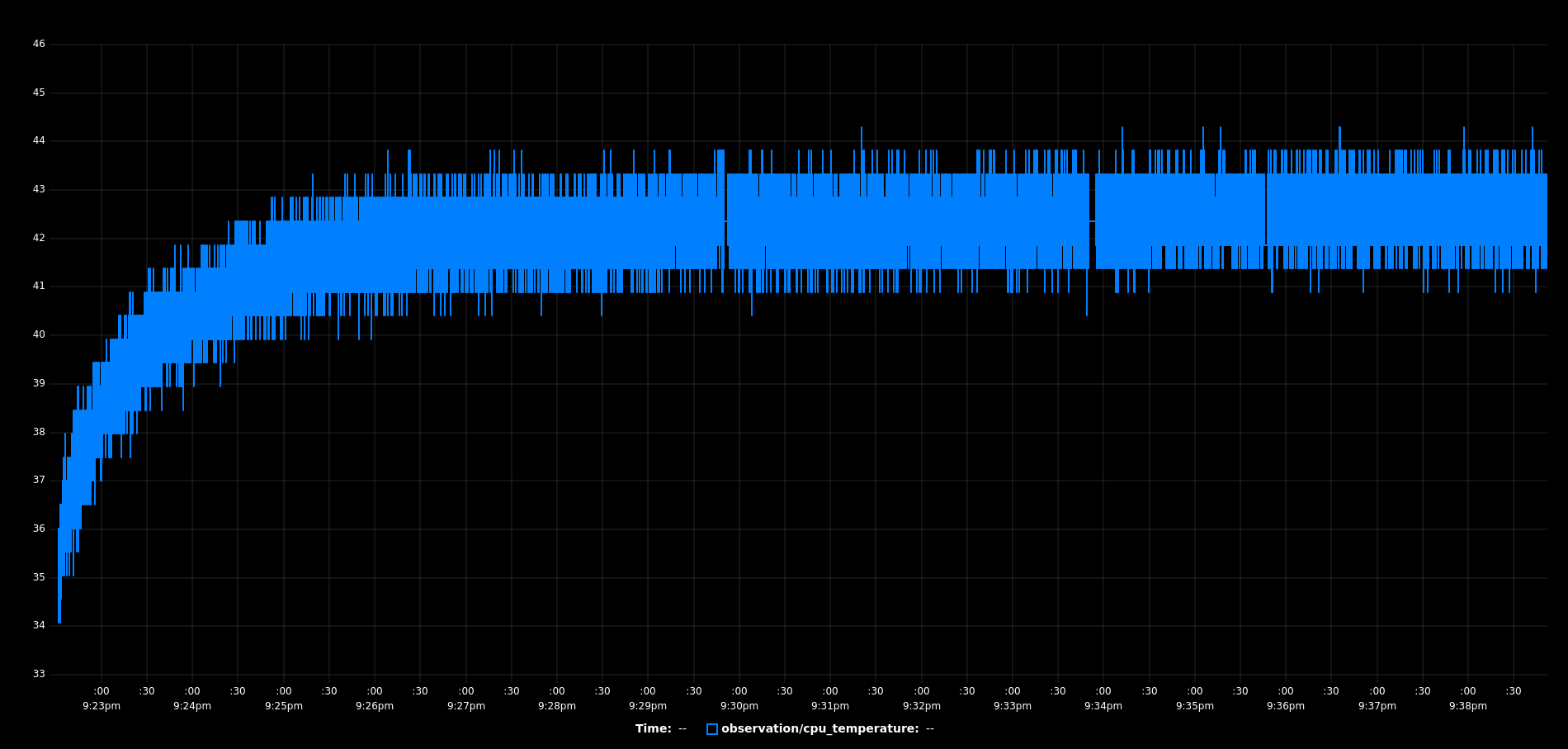
The fan is effective immediately. It brings down the CPU temperature to an equilibrium around 43 °C while the balancer is running full steam:
![]()
Now the issue has become noise 😅 The fan's continuous 32 dBA relentlessly drill into the ears of neighboring humans, whose thoughts are inevitably driven to the next revision: smaller fan, less dBA!
→ 🔉
-
February 2022 update
06/05/2022 at 11:10 • 0 commentsHere comes a shot of the robot in its natural habitat: the living room!
The main improvement in this update lies in the locomotion software, which performs smoother motions and allows the robot to crouch down further.
There is also a hack, documented in the code as the non-minimum phase trick, to improve transitions from standing to driving with the simple PID balancer. Some pointers to dig further: this hack helps handle the non-minimum phase nature of balancing systems (the fact that to go one way one first needs to go "a little" the other way, like counter-steering in bikes) without going for full model predictive control.
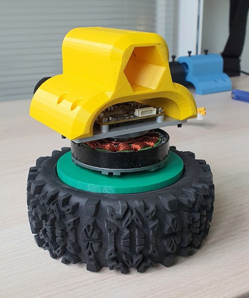
The small wheels (OD: 100 mm) on Upkie are nice because they are sleek, which fits well the assumption made by the PID balancer that controls the velocity of the contact points with the ground, unfortunately they are also a bit small which doesn't fit the ankle design so well. That, rather than knee torques, is actually what limits how much the robot can crouch before it starts scratching the hell out of the floor (^_^)
Upkie wheeled biped robots
Wheeled biped robots with fully open source hardware and software.