Ulrich
-
Housing and Desk Mount
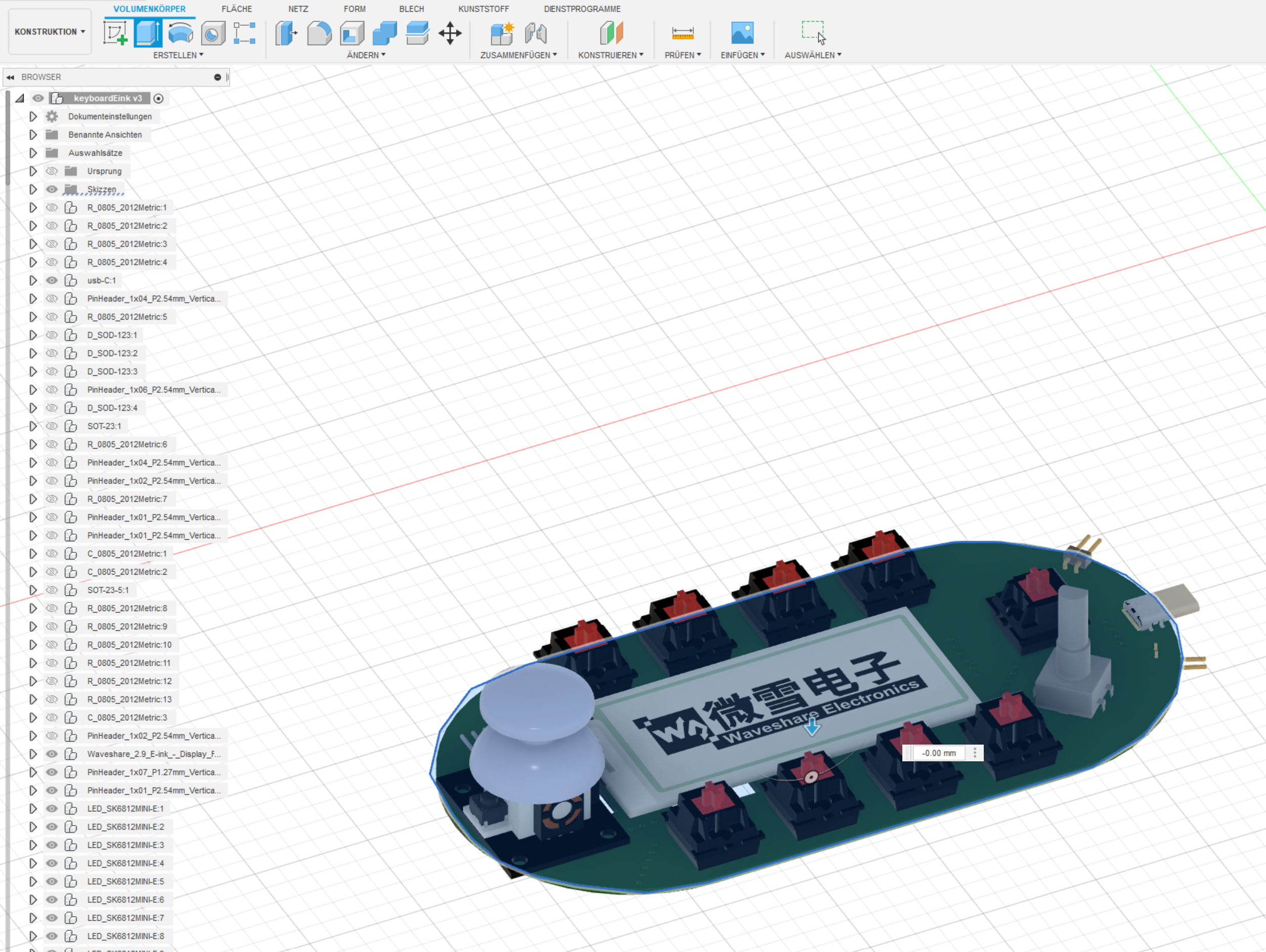
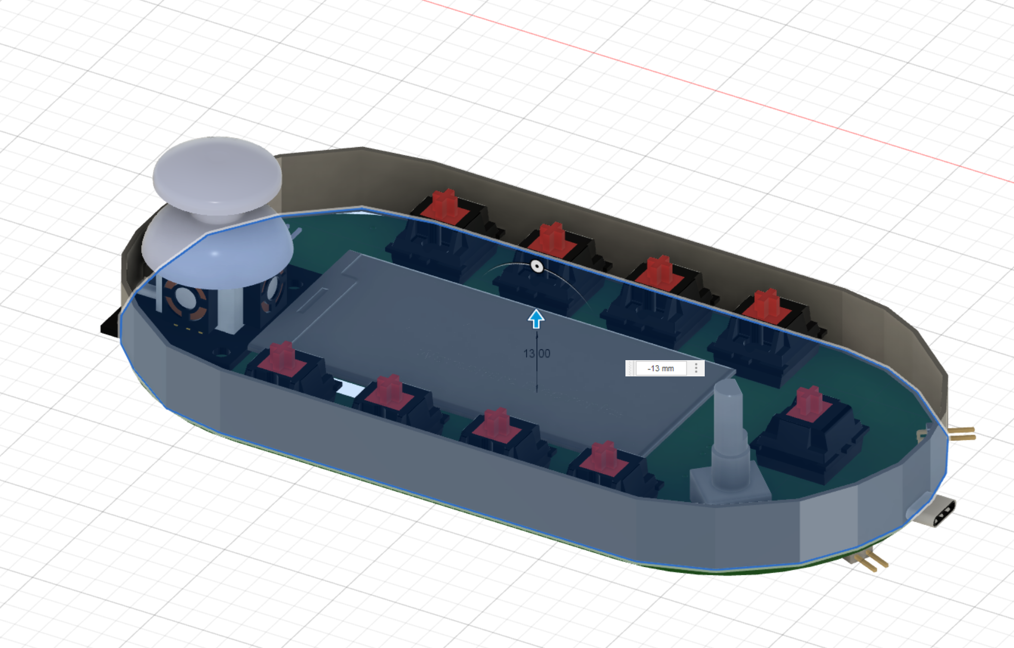
03/12/2023 at 09:55 • 0 commentsThis project is sitting on my bench now quite a while.
It works and enhanced my daily workstream quite a lot.
But you know a project is more valuble if there is a professional housing around it.
So far I was using it with the PCB only. The reason for this is: I am totally not good in designing housings for PCB.
I am just a complete noob in AutoDesk Fusion 360.
Therefore I visited one of my local Maker Shacks(AIxpress.io) and learnt in a class some stuff in Autodesk Fusion 360 regarding 3D printing.
![]()
Extrude:
![]()
-
Make it compatible with Retro-Go Gameboy Emulation?
07/14/2022 at 19:20 • 0 commentsThinking right now if I should make this device compatible to Retro GO Gameboy Emulation.
Link to Retro-Go: Retro Go Github
I have everything ready for this device and would just need to recompile the software:
This would add Gameing opportunities like this one...
and then ther migfht be an option to run doom.
What do you think about it?
-
Wifi Manager, Key Assignment, API Keys
07/03/2022 at 19:34 • 0 commentsDuring building I decided to make the keyboard cofigurable easy.
I did not want to reprogramm with the Arduino IDE the whole Mikrocontroller everytime I want to change the keys with a different meaning.
Luckily i stumbled across this video
of Brian Laugh
Here it is described how to use ESP32 as a webserver.
(nothing new for me, maybe for others)But he described how to store Wifi Passwords with Wifi Manager.
The really important part of this video was the extension of the Wifi Manager with personal Keys, HTML Objects, Web Formulars, Check Boxes,.... and store data of this field in the SPIFFS storage.
So I decided to use this idea and adapt it to my needs. With this in mind I built the complete sketch.
My Idea:
If a special Input Key(Reset button) is pressed during startup the WiFi manager configuration page is loaded. This gives the user the possibility to change parameters of the device on the fly. With two check Boxes you may enable special Keys like "Shift", "CTRL", "WinKey"
You may find my code here on the Github part of this Project: LINK
-
SW development stuck.....due to PC crash
06/29/2022 at 06:22 • 0 commentsLast Thursday my laptop (ThinkPad t460s) all of a sudden died. It simply does not start any more.
After several repair attempts it looks like the Mainboard of my pc is damaged. I ordered a replacement motherboard and I am waiting for the parts right now.
Maybe I am lucky and can make the harddrive of this laptop working external and recover the files.
On this laptop I got all the files and I was about to Upload to GitHub this weekend.
Wish me luck 😃🍀
Update 5 days later: I had to replace the Motherboard of my Laptop. Luckily I got a spare part for 25 €
Downside: Now I only have 4Gbyte of RAM because the RAM of my Laptop seams to be broken as well.
Nevertheless I recovered the Project Files and backuped everything.
-
Keyboard Illumination Check and USB Mode
06/19/2022 at 15:13 • 0 commentsLets Check the RGB Leds: Brightness and Colors:
![]()
As you can see the Board is now fully powered by USB.. The Programming Connector is removed.
-
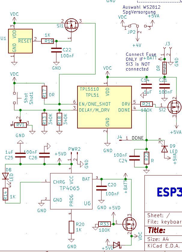
HW Bring UP Part II: RTC LOW POWER GATING
06/19/2022 at 15:02 • 0 commentsYou might remember: I always planned to have a very low quiescent current.
Most of the time your shortcut keyboard sits around and is doing nothing.
Some says ago i stumbled over this TPL5110 Module on Adafruit. This is an excellent idea to get more out of your battery if you really want to get the most jucie of your battery.
Basically it cuts the complete Power of your circuit after a while and only needs 50 nA(Yes Nano Amps).-.-. This is way less than any Microcontroller in sleep mode.
Schematics:
![]()
So time to bring this part of the PCB to live:
You can see in this video: In Low Power Mode my Multimeter can not measure any current. Once started by a keypress the complete board starts up.. the ESP32 starts and the board consumes 125 mA(average due to wifi activity)
Once the Mikrocontroller has done all its jobs it sends a shutdown Signal to the TPL5110 on the DONE pin.... This Shuts down the Power Supply and the low current time starts.
If there is no DONE Signal sent by the Mikrocontroller an automatic shutdown is performed
-
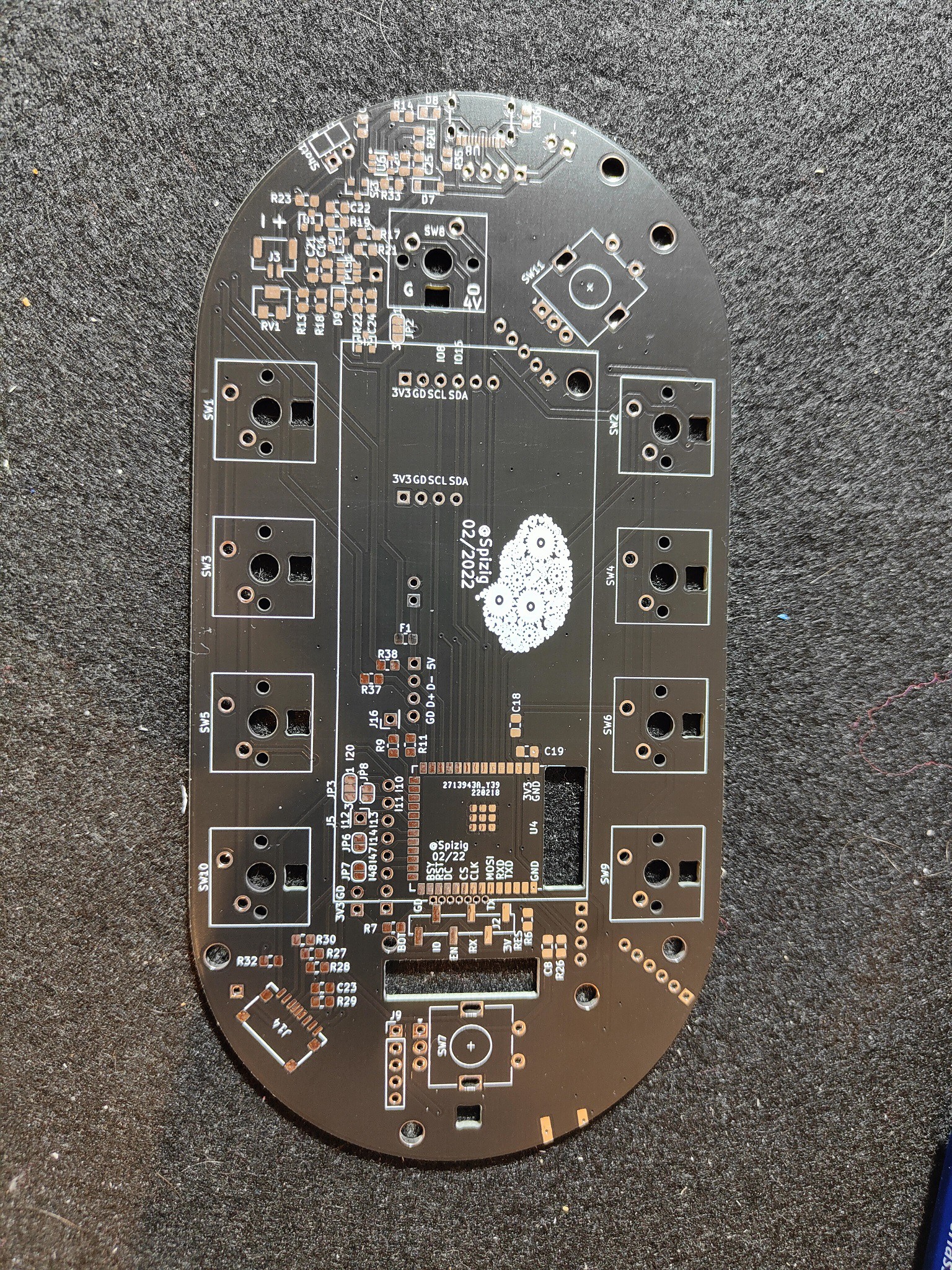
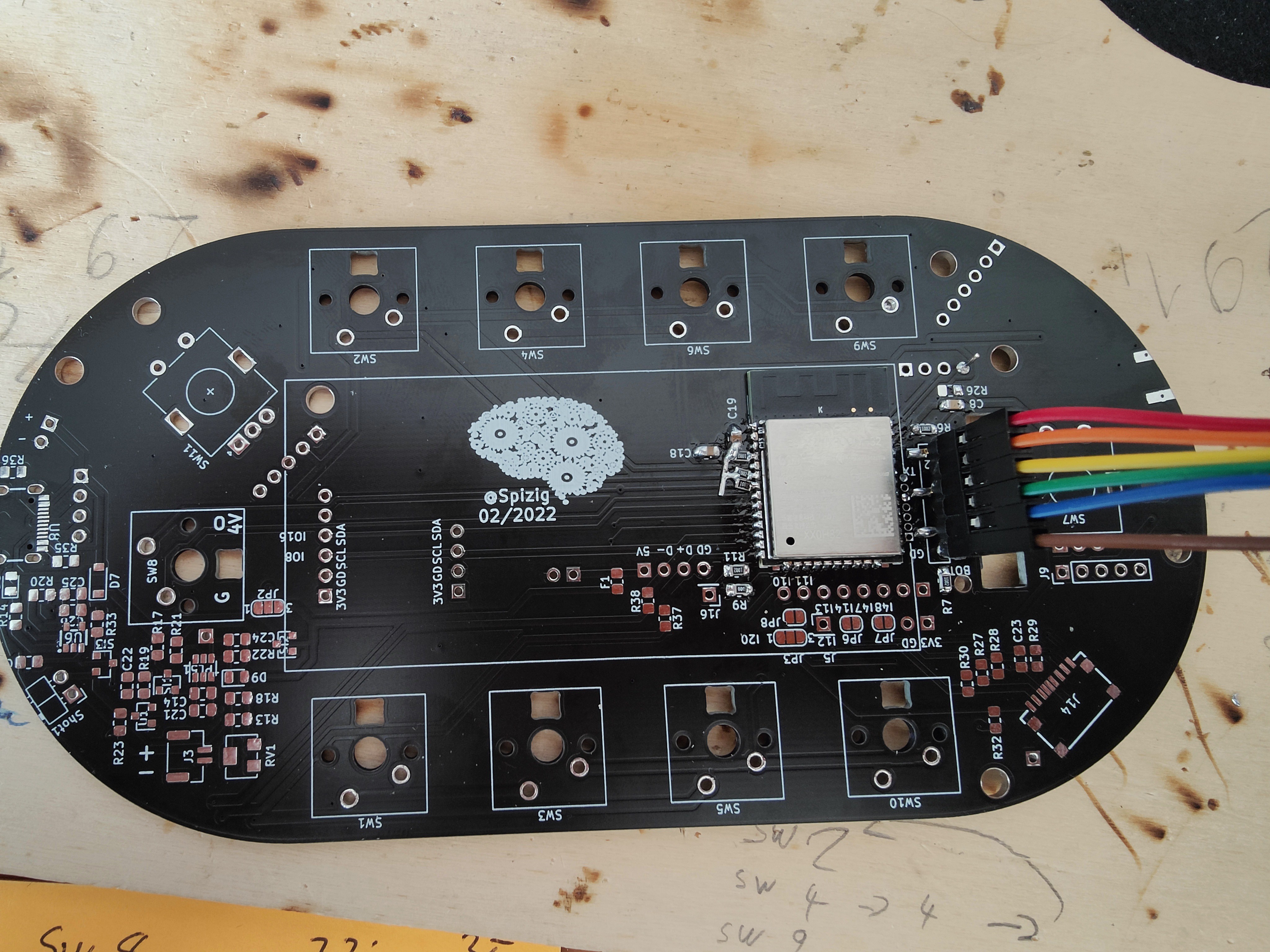
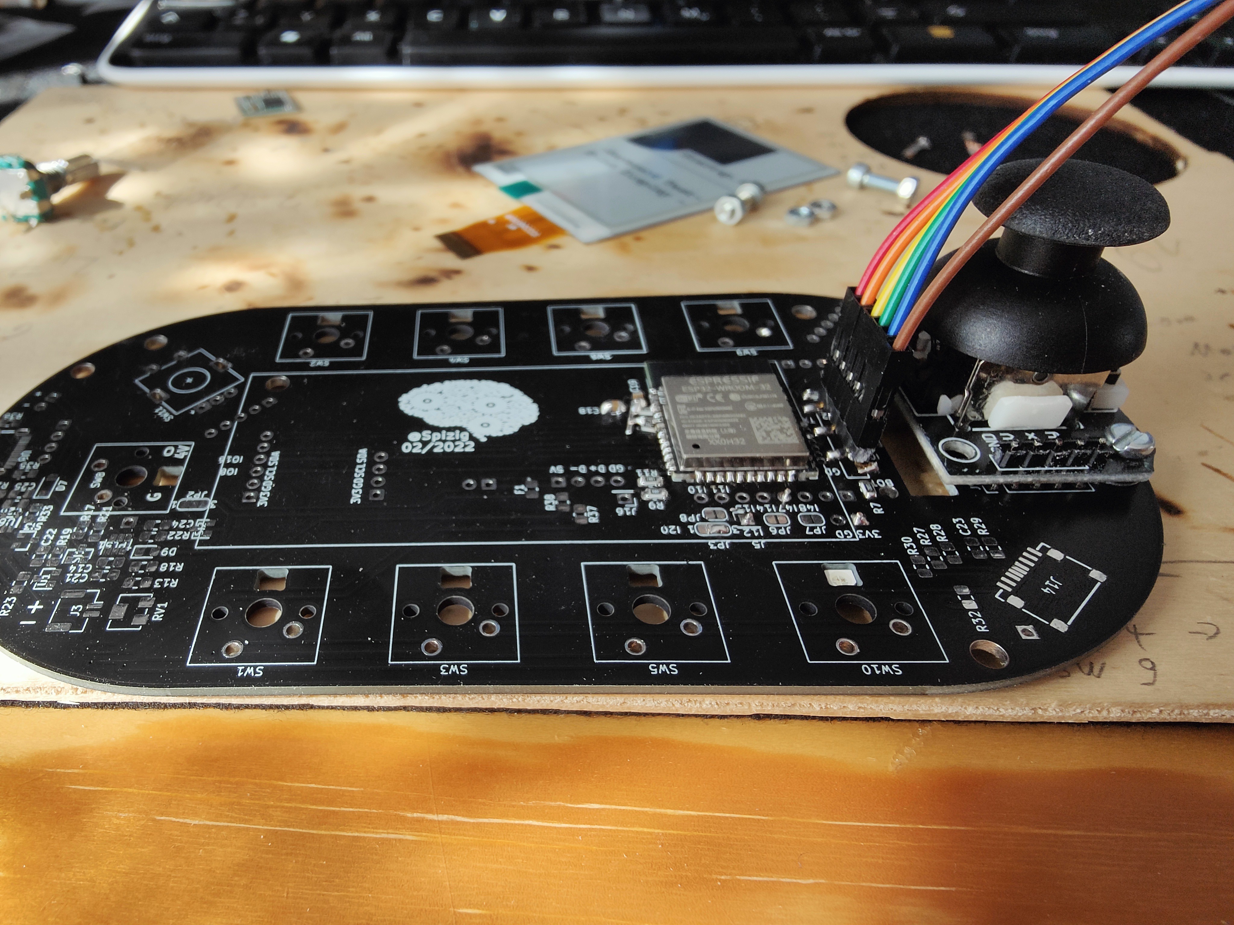
Hardware Bring UP & Soldering
06/19/2022 at 14:51 • 0 commentsI ordered my PCBs at JLC PCB in March.... 10 days later the PCBs arrived in the usual blue box.
I sourced some missing parts that I had not on stock as well on LCSC.
Time Machine:
After some waiting time the PCB Boards arrived and I got all the parts that I needed for a first HW Bring Up and testing.
PCBs
![]()
![]()
Soldering by Hand all the Components:
During this time the ESP32-S3 Wroom was still hard to get and I only had 2 sample parts in my hands
Due to lack of experience with the ESP32-S3 chip and missing parts I tried my luck withe the good old ESP32.
That was as well the reason why I designed the board to work mostly(basic features) on the ESP32 and the ESP32-S3:
I am soldering all my components by Hand... On one hand this takes more time... but on the other hand you can bring up the Hardware step by step. In the designphase I already considered this... Thats why I am using 0805 SMD components. They are good to handle and easy to solder. But still you save a lot of space compared to wired components
![]()
You may see this small Resistors on the left of ESP32 Wroom. These are some Pullups that I forgot to design.
With some Scissors I could test alle the Keyboard Keys without wasting them and soldering them to the board.
The basic function is working.
Nevertheless I found out YOU should never use and ADC2 Pin while WiFi is active on the ESP32.
Otherwise the ADC Values you read out are a casino game.
Sometimes you win --- sometimes you loose.
![]()
Lets Try out the RGB LEDS:
Same on the ESP32-S3:
-
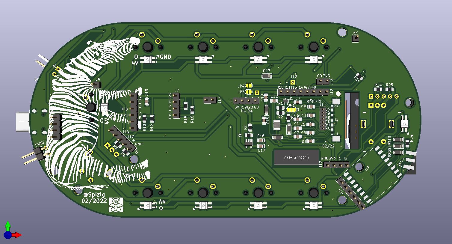
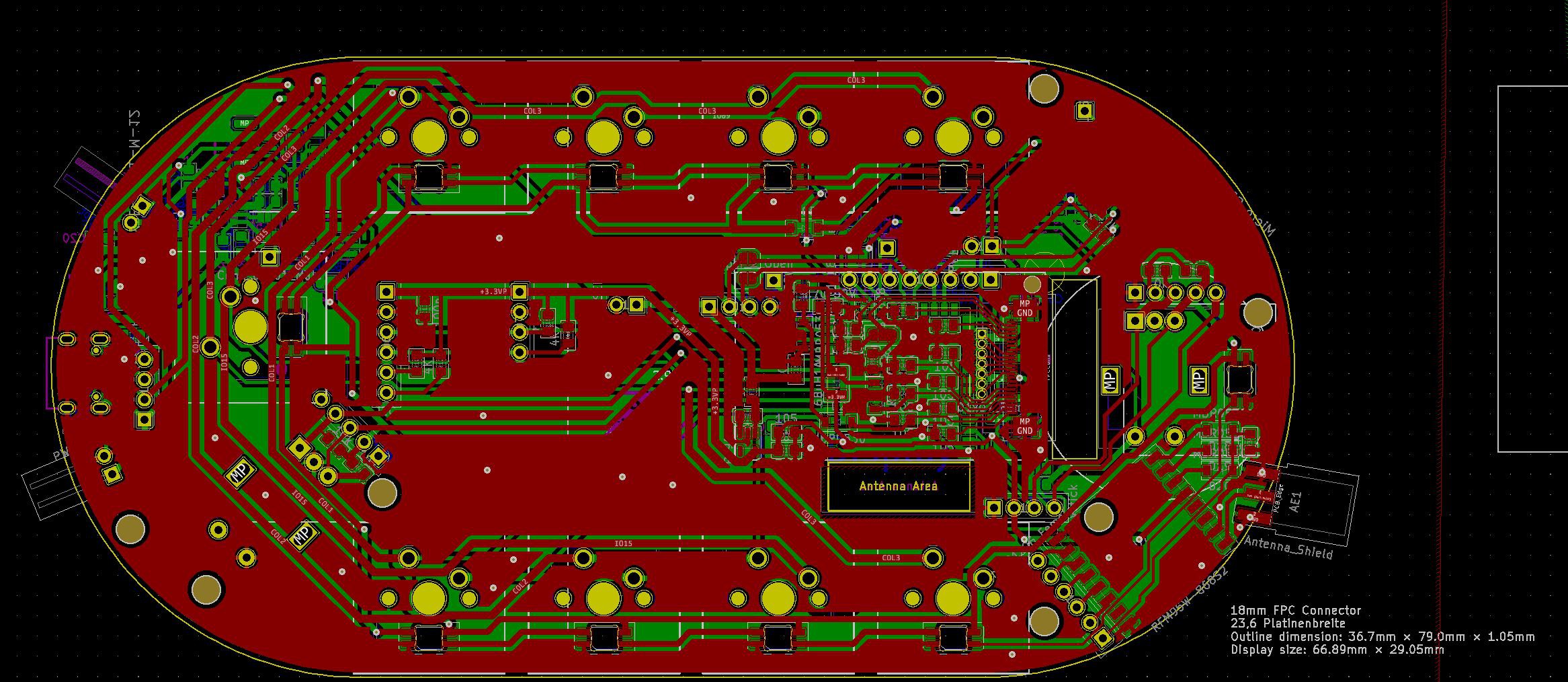
3D View in KiCad, SilkScreen Art
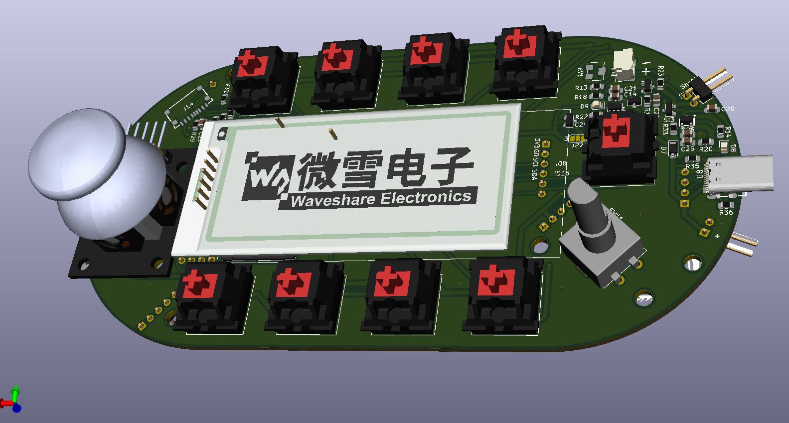
06/19/2022 at 13:26 • 0 commentsBefore Sending a Board to production I always check my Design in a 3d Viewer.
![]()
You may notice this Joystick in the upper left: I noticed it is cheaper to buy these modules on a PCB than building one my one.
Bottom:
![]()
What do you see in this pictures:
- I decided to leave some space between the keys. This gives me the most opportunities in choosing different Keycaps
- I added two I²C Connector headers J7 and J5. On this headers you may add some additional sensors like Air Quality SGP30 or Gryo MPU9250
- You may see the Space for the RFM95 Lora Module on the backseide on the lower right side. This was really a pain to layout it in this tight space. But I still decided to add an SMA Connector for an external Antenna.
Before Production:
In earlier Days I always printed out parts and doublechecked of everything fits perfectly with the parts. From time to time I still do this.
-
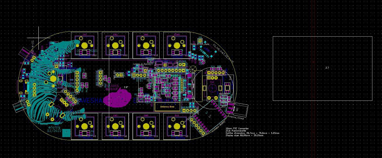
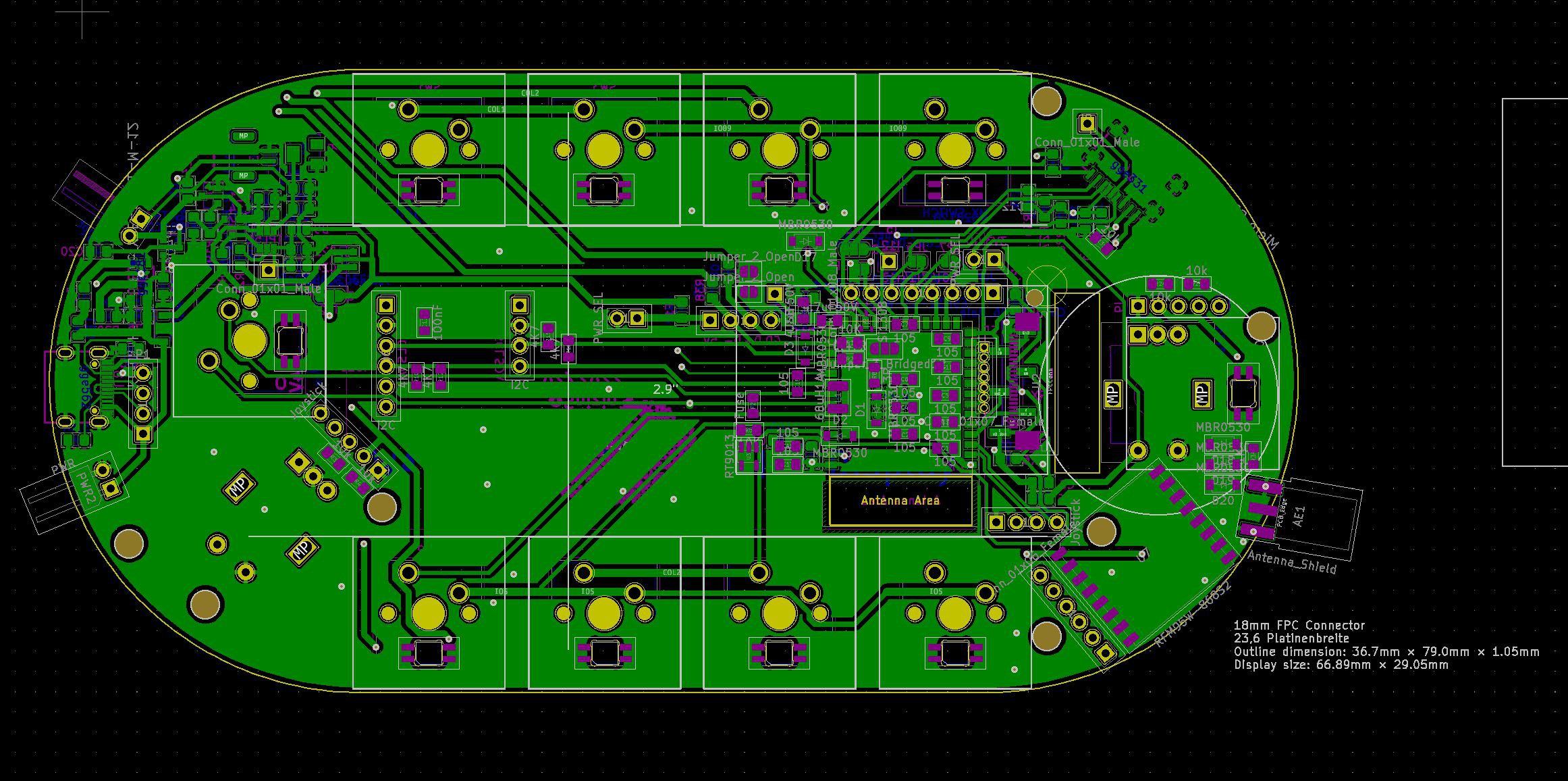
Design this Board as a PCB
06/19/2022 at 13:17 • 0 commentsAs usual the board looks best if you design it as a PCB.
With low cost PCB printing alternatives like jlcpcb, pcbway,... you can get your PCBs nowerdays really cheap.
I use KiCad Open Source Software to design my PCBs.
Goal was to have 9 Keys orientated around the Board and a proper position for a volume Knob(Rotary Encoder).
The keys should be located around the EInk Display. During the Design phase I could not decide between the Waveshare 2.9" and the Waveshare 2.7".
If it comes down to Pixel Area the 2.7" has a larger pixel Area but oriented more in a square format(even the numbers woudl guide you in another direction)
On the other hand thge 2.9" was oriented more in a landscape mode and was capable of faster updates.
This decision to make faster EINK updates dominated the pro/Con list.
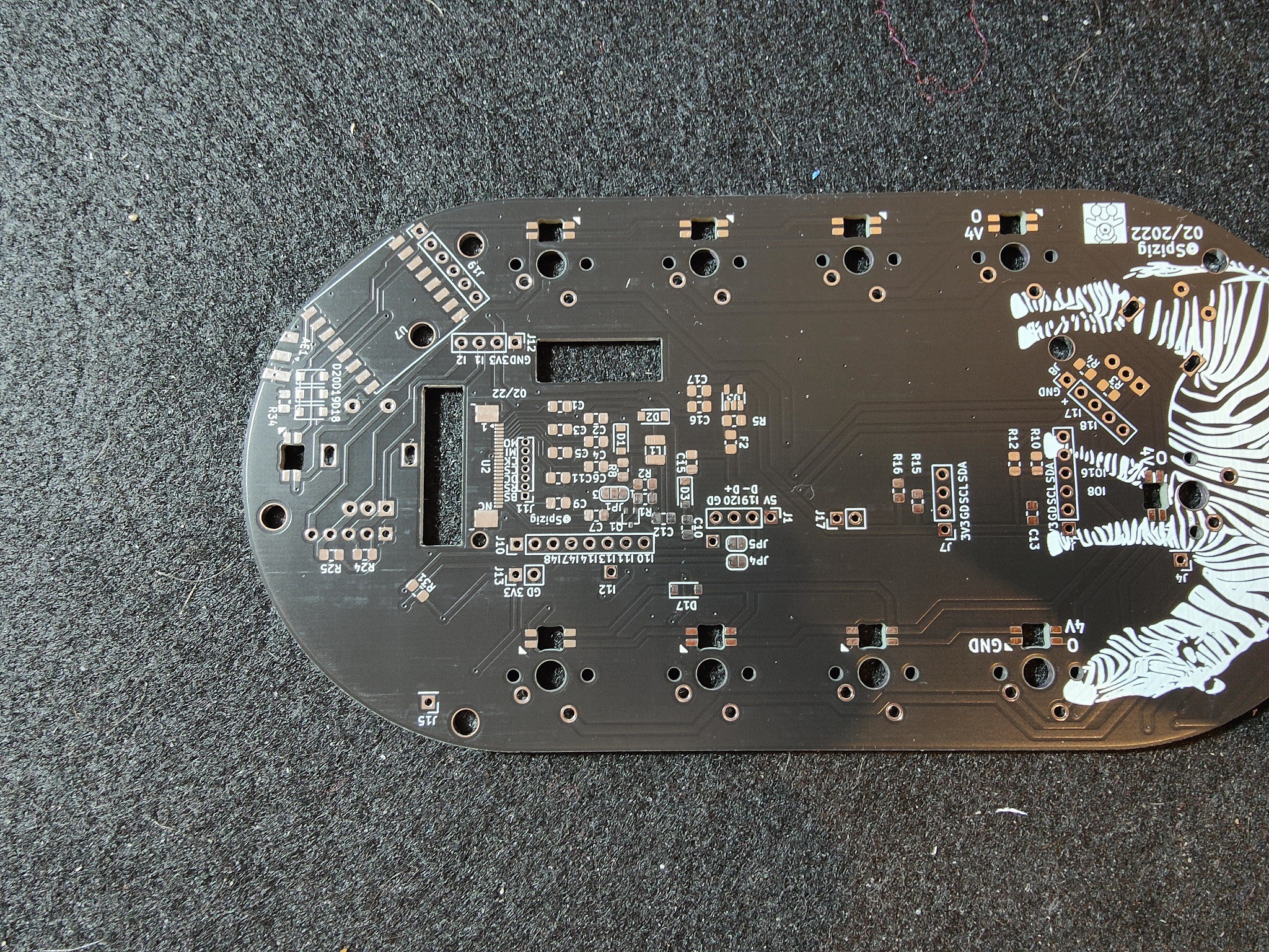
In the picture below you see The Size of the 2.7 EInk Board compared against the final layout with a 2.9".
![]()
(Please note the Art in the silk Screen)
So how does the board look:
Top Side:
![]()
Bottom Side:
![]()
Honestly Speaking I was using this EINK Part in a different design before. Thats why i recyled this part for this poject
What gave me most trouble in this design:
- How much space between the keys.
- How much space does a Joystick need?
- How much space does a Volume Knob need?
- Does the RGB LED Shine trough the MX Keys Buttons bright enough?
-
Time for some Options (SDCard, LoRa, USB-C Connector)
06/09/2022 at 13:09 • 0 commentsDuring the design phase I had the idea: Why not use some more board Space and add dome extra features.
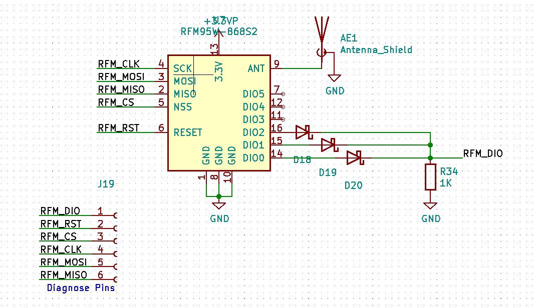
LoRa - Long Range Communication with Wireless RF on 868 MHz(Europe)
Adding Lora is always good... This gives the opportunity to use this Keyboard out in the wild.
With this feature you may use this board as an simply remote control with Eink. Due to the low power consumption in Standby(see RTC) the battery may last for a very long time.
If you use a RFM95 Board all the hassle with RF trimming, Voddoo becomes easy.
This module is widely availible and you can use it for Helium or TheThingsNetwork
You just need to solder the pins and connect some wires to it.
![]()
As an Antenna Connector I decided to usa an SMA Connector. This helps if you want to connect an external Antenna later on
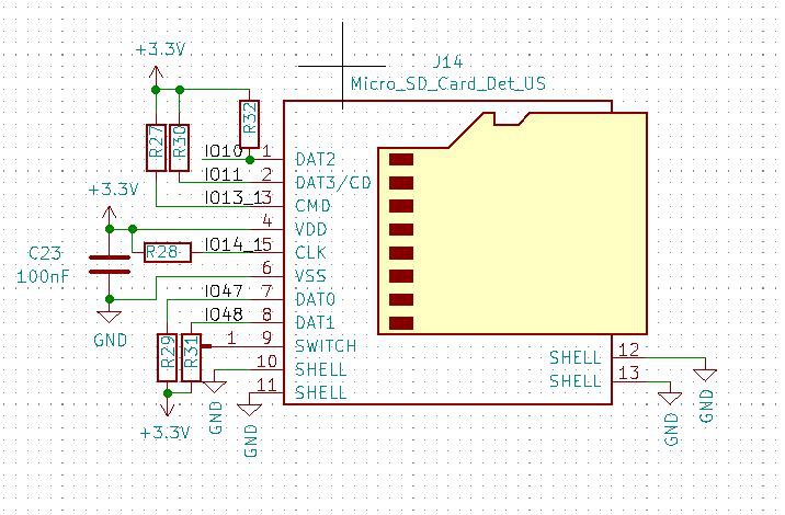
SDCard
While buying the TP4065 Battery Charger on LCSC I was browsing for some "fill my shopping cart with cheap stuff that I don't feel guilty just ordering 20 ICs"... and i found a very cheap Micro SD Card connector TF-SMD_XKTF-0803-0 - LCSCC381083
![]()
Why not give these 20cents Card holder a chance and try it out. Additional storage is always good.
All you need to to is add some pullup resistors to make this thing working.
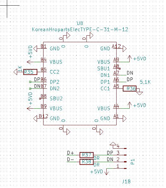
USB-Type C Connector (KoreanHropartsElecTYPE-C-31-M-12)
New Day: New Ideas: The ESP32-S3 Mikrocontroller has the possibility to use it as an HID Keyboard device, as a Mass Storage Device ,... and several other USB profiles.
It did not want to be stuck on the old Micro SD or USB A Connector..It was time for USB C. The Downside: USB C connectors are hard to solder by hand...
My Oprinion: Don't do this if you are not a very experienced in soldering
![]()
To make USB C Work you need to connect two 5.1k ressitors to the CC1 and CC2 Pin. Without them USB C won't work
LowPow E-Ink ShortKeyboard BLE, Wired, LoRa,Wifi
A Ultra Low Power Shortcut Eink Keyboard that works on Bluetooth or Wired. With Wifi, LoRa, SD Card, Joystick, Rotary Volume Knob