-
2Overview & tips
![_DSC0414]()
PS: all the instructions are also available at the documentation page.
To make your own E-TKT you will need to:
1. 3D print
I highly recommend you to have a 3d printer accessible as you might need to test and tweak the printing settings, since this project demands a certain precision in the fittings;
2. order a PCB
It’s design was oriented to low cost manufacturing (4 layers). The two internal layers are ground planes, so it might work with only 2 layers for even lower costs (but it wasn’t tested). Don’t forget to order a stencil for the front face (not needed for the back) together with the PCB.
3. buy components
For some electronic parts, you might need to search for alternative drop-in replacements (same specs & footprint) as right now there is a general shortage for semiconductors.
4. mount the components on the PCB
You can place the components manually in the PCB and then use a home electrical oven/toaster to solder the SMD components. There are PTH headers in the back face and a single SMD electrolytical capacitor that will be easy to deal with a simple soldering station.
5. flash the firmware
Very simple process, but please don’t forget to add the data files together with the firmware.
6. assemble the whole package
After making sure the system is working properly, you can proceed to cable management and physically mounting the parts together.
7. calibrate
The final step makes sure the daisy wheel letters are aligned to the tape and works along with the right pressing force. There is a handy calibration mode built-in the web app ;)
PS: the PCB order along with the components and it’s assembly (steps 2, 3 and 4) might be outsourced by using a turnkey PCB service, but it is funnier to DIY to learn by doing!
-
33D printing
![_DSC0212]()
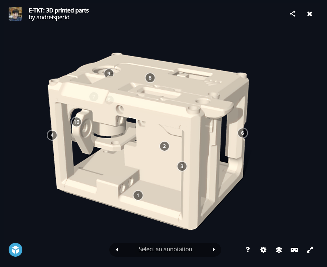
16 parts in total, using approximately 220g of filament (I’ve used PETG).
Click above to see an interactive 3D model.
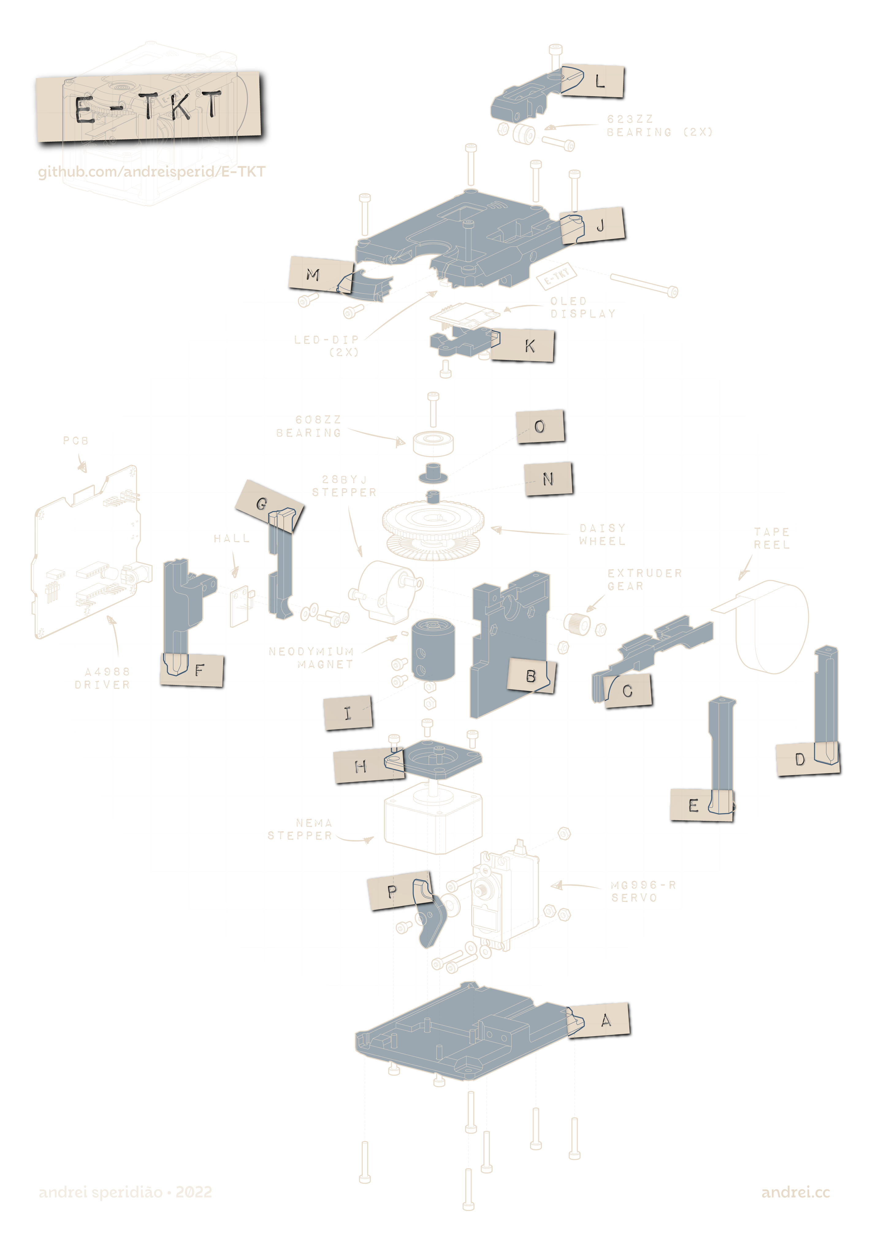
📐 All the .stl provided are in the correct orientation for optimal printing:
- A_bottom *
- B_wall *
- C_wall_track *
- D_pillar
- E_pillar
- F_pillar
- G_pillar
- H_nema_cover *
- I_nema_wheel_hub
- J_top *
- K_top_screenholder
- L_top_tapefeeder
- M_top_wheel_cover
- N_wheel_coupling_bottom
- O_wheel_coupling_top
- P_press
* needs support
🎛️ Recommended settings
- Layer height: 0.20mm
- Infill: 20%
- Wall line count: 3 + 1 (alternating extra wall with Cura)
- Top/bottom layers: 5
-
4Electronics
![_DSC0364]()
Board
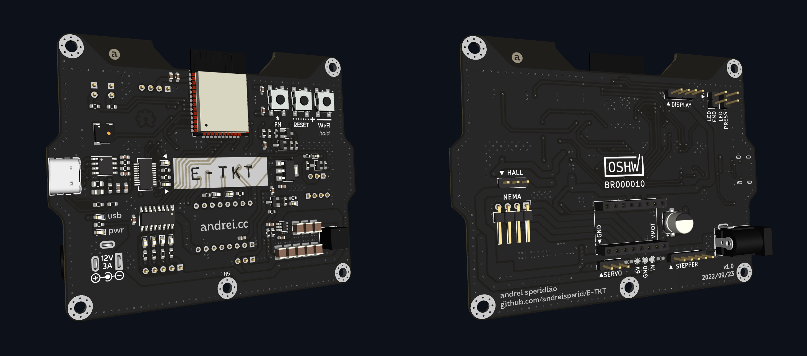
Schematics
![image]() You can find the PDF in the files section.
You can find the PDF in the files section.
Subsystems
Power
- 12V needs to be provided by an external power supply with at least 3A (real) to deal with servo peaks current while pressing the label. It supplies both the stepper drivers directly.
- 6V out of the bucket converter and is provided for both the servo and hall sensor. The peak voltage tested on oscilloscope was +1V surge when the servo stalls. *
- 3.3V is provided by the AZ1117 linear regulator, which receives power directly from the 6V rail.
Important: Logic level MOSFETs (BSS138) were implemented because the ESP32 uses 3.3v logic, we need this conversion for parts that are running on 6V (servo and hall sensor).
* Using a bucket converter for the 6V rail is preferred due to the high step from 12V, but a cheaper alternative using a L7806 (1.5A) is offered at the PCB back side. For that, you should not mount the bucket converter components (C_POW_IN_1, C_POW_IN_2, C_POW_IN_3, U_POW1, C_POW_BST_1, L1, C_POW_6V_FF1, R_POW_FBT1, R_POW_FFB1, C_POW_OUT_1, C_POW_OUT_2, C_POW_OUT_3, C_POW_OUT_4, C_POW_OUT_5). But IMPORTANT, this exact setup wasn't tested on this exact PCB (only in the preliminar prototype), so do it at your own risk.
Processing & wireless communication
- Using an ESP32-WROOM-32D-N4, with an integrated antenna.
Serial USB communication
- An FT231XS-R is used for flashing the firmware through an USB-C 2.0 port.
Label press
- The MG996-R servo has a maximum constant voltage of 6V. Constant higher tension tends to damage it.
Character selection (daisy wheel)
- A NEMA stepper driven by a A4988 breakout and a KY 003 hall sensor for homing the daisy wheel.
Wifi reset
- When this tactile button is pressed while booting the saved wifi credentials are cleared.
Feeder
- 12v reduced stepper motor (28BYJ-48) driven by a ULN2003 darlington array.
Graphic user interface
- Running on 3.3v, an I²C OLED display and two DIP LEDs mounted into the J_top piece.
Buzzer
- Optional magnetic buzzer that plays notes for audible feedback.
Stackup
- Front (F.Cu): most components + mixed signals & power + ground plane;
- Inner 1 (In1.Cu): ground plane;
- Inner 2 (In2.Cu): 6V plane;
- Back (B.Cu): few components + headers + mixed signals and power + ground plane.
-
5Bill of materials
Please check the components section.
-
6Firmware
![_DSC0743]()
- Clone the repository;
- Make sure you have the framework and all the libraries installed on your computer (I use Visual Studio Code with PlatformIO and recommend it!);
- Flash the code into the PCB using an USB-C cable *;
- Upload the files (“data” folder) to the ESP32 using SPIFFS *.
* don’t forget to hold the *FN button to enter DFU mode
PS: if you want to know more about the code, please check the firmware and the app scripts.
-
7Assembly
Next we'll be following 10 steps for assembling the parts together. Then we will proceed to connecting the device to a wireless local network, reeling the label tape and finally calibrating the device.
If you need an overview, please use the exploded view in the instruction number 1.
-
8#0 Assembly: harnesses
![_DSC0484]()
In this first step, we will prepare several parts that will be used through all the assembly, interacting with multiple subgroups.
Hall sensor breakout
![_DSC0490]()
- if the breakout has a male header, remove it first with care;
- solder a 3x pin female 2.54mm header to the breakout’s back face;
- fold hall terminals by 90° at approximately 7mm from the board, making sure the sensor is perpendicular to the breakout;
OLED display + harness
![_DSC0486]()
- if the breakout has a male/female header, remove it first with care;
- solder a 4x vias flat cable directly to the breakout (there is no space for a header when assembled);
- OBSERVE THE WIRING: in this specific display model, the VCC and GND needs to be switched;
- crimp 4x female 2.54mm connectors;
- as in the above photo point of view, the vias must be: SDA, SCL, VCC, GND.
- place a 4x plastic case (nevermind the 5x connector case, I didn’t have 4x available);
NEMA harness
![_DSC0488]()
- cut the original 4 vias stepper cable to use the extremity that connects to the motor;
- crimp 4x female 2.54mm connectors;
- OBSERVE THE WIRING: the inner wires should be switched; ;
- place a 4x plastic case (never mind the 5x connector case, I didn’t have 4x available);
LEDs + harnesses
![_DSC0491]()
- cut the terminals of the two DIP LEDs;
- solder each LED to a 2 vias flat cable
- I recommend to use individual thermo retractable sleeves for each terminal to avoid short circuits
- do not crimp the connectors yet, we will need to pass the cables before that.
-
9#1 Assembly: NEMA
![_DSC0500]()
In this first step, we will prepare the NEMA stepper sub-module, responsible for the daisy wheel character selection.
Cover
![_DSC0502]()
- place the H_nema_cover on top of the NEMA stepper motor, and fix it with 4x m3x6 screws.
Magnet polarity
We need to know the right magnet polarity to trigger the hall sensor, otherwise the device will not be able to home itself.
![_DSC0505]()
![_DSC0506]()
- for that, temporarily mount the hall sensor breakout into the PCB and turn it on;
- avoiding any short circuits, pass the magnet extremities to the sensor, careful, as it might be attracted to the terminals;
- when the right side is found, mark it with a pen;
- turn the PCB off and then disassemble the hall sensor breakout;
Wheel hub: magnet
![_DSC0508]()
![_DSC0509]()
- with the help of a plier, place the magnet into the I_nema_wheel_hub with the mark outside;
- the magnet must be leveled to the surface, otherwise it might hit the sensor when rotating;
Wheel hub: fixation
![_DSC0515]()
![_DSC0516]()
![_DSC0518]()
- now, place 2x m3 nuts into the slit underneath the I_nema_wheel_hub;
- a plier is helpfull for the initial insertion, then an allen wrench helps to slide it in;
- be careful with the second nut, otherwise it may go beyond its proper spot;
- place 2x m3x8 screws just to make sure they grab the nuts, but do not fasten them yet;
NEMA + wheel hub assemble
![_DSC0519]()
- slide the cube to the stepper motor, making sure the chamfer matches both parts;
- if you have having trouble, make sure the screws are not tightned;
- again, do not fasten the screws, we will have then tightened later.
Result
![_DSC0520]()
-
10#2 Assembly: PCB
The PCB gathers electronic breakouts but also serves a structural role. That means it is adjacent to several mechanical parts.
![_DSC0521]()
PCB + stepper driver
![_DSC0523]()
- place the A4988 driver on the board, observing the VMOT and GND markings to make sure it is properly oriented;
PCB + hall sensor
![_DSC0524]()
- place the hall sensor;
- it isn’t going to hold steadily into the connector and that’s expected;
+ F_pillar
The F_pillar will make sure the hall breakout stays firm in position, while at the same time aggregating the PCB to the overall structure.
![_DSC0526]()
![_DSC0527]()
![_DSC0528]()
- place two nuts in the F_pillar slots;
- slide the F_pillar from the PCB side;
- insert 2x m3x10 with 2x washers and fasten them;
+ NEMA + G_pillar
![_DSC0529]()
![_DSC0530]()
- connect the NEMA harness to the stepper motor;
- then, connect it to the PCB;
- mount the G_pillar in the opposite side of the PCB;
- very carefully, place the assembly into a surface.
Result
![_DSC0531]()
E-TKT: anachronic label maker
An open source label maker that fuses together both old and contemporary technology to create something as ubiquitous as... EMBOSSED LABELS!
 Andrei Speridião


 You can find the PDF in the files section.


Discussions
Become a Hackaday.io Member
Create an account to leave a comment. Already have an account? Log In.