Close
0%
0%

Z80 Reverse-Engineering And Hacking Adventures

What else can I say?

Similar projects worth following
Ziggurat29 and I are now on our third(?) Z80-based machine reverse-engineering/hacking adventure. He's WAY smarter than I... But I tend to ramble and get way off-topic, burying his hard work amongst my rants. Maybe a dedicated project-page can keep it a little more sane and plausibly organized.

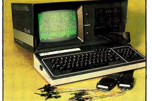
Our first adventure was with a weird old piece of test-equipment which barely seems to have existed, according to the internet. A Kaypro-based Logic Analyzer.

Our second adventure was a bit more common of a machine, still available in large quantities... The good ol' TI-86.

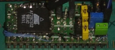
Today we're working on yet another weird old seemingly-non-existant piece of test equipment... A "Spectradata SD70," which we are guessing controlled a spectrum-analyzer which, of course, we don't have any info about, either.

Here, since I'm usually so disorganized in my logs, maybe a 

Table Of Highlights:

Intro

Reversing For Fun And Profit - Why I Like To Do It --Ziggurat29

Z80 Hackery With Ziggurat29 - A "Brief" History --Eric

Spectradata SD70 - Eric's Interest

Reverse Engineering

Spectradata SD70 - The Beginning

Ports

(Surely more logs than listed here)

BIG NOTE:

If you're reading the logs through the logs-list, rather than one by one, you're missing quite a bit, as many of our discoveries, both related and unrelated to the log itself, wind-up in the comments.  Heh... whatcanyado

SpectraDataSD70-20220622a.lst

current disassembly work; very much a work-in-progress

plain - 342.98 kB - 06/22/2022 at 15:54

Download

Z80Manuals.zip

These are datasheets and whatnot for the stuff on the SD70 board. The SIO and PIO technical manual are put here separately just because they are so large and exceed the limits of this site. But this has most of the juicy stuff.

x-zip-compressed - 24.34 MB - 06/21/2022 at 17:40

Download

Zilog Z80-SIO Technical Manual.pdf

you kinda need these special manuals to get the real skinny on how these peripheral chips work -- the datasheets are just high-level details. The DART is, I guess long since discontinued, but the SIO is similar in that it does what the DART does and also some ancient synchronous protocols as well. But the register detail is important. This one is big, so I couldn't zip them all into one package.

Adobe Portable Document Format - 24.10 MB - 06/21/2022 at 17:36

Preview

Zilog Z80-PIO Technical Manual.pdf

you kinda need these special manuals to get the real skinny on how these peripheral chips work -- the datasheets are just high-level details. This one is big, so I couldn't zip them all into one package.

Adobe Portable Document Format - 25.76 MB - 06/21/2022 at 17:34

Preview

SD70.HEX

Spectradata SD70 v1.8 ROM - Intel Hex

hex - 45.01 kB - 06/15/2022 at 20:16

Download

View all 6 files

  • 90's LED Matrix -- Weird Decisions

    Eric Hertz08/30/2023 at 12:51 0 comments

    I've acquired and am rebraining/repurposing a Red/Green LED matrix sign, made in the early-mid 1990's with a densely-peripheralled Z80 processor board (which, later, might be fun to also repurpose? Sorry @ziggurat29, I haven't gotten you those ROMs, yet!)

    The matrix boards are pretty simple: 74HC164 serial-in parallel-out shift-registers drive the columns via NPN darlington arrays. A couple simple 3in-8out demultiplexers choose the row, and drive some big ol' discrete PNPs. Pretty simple to interface.

    Each board is a matrix of 45x16 bicolor LEDs, and as I understand, it had four of these boards, and one 45x16 red-only board at the end. So, we're talking some 400+ columns need to be shifted-in, then the row gets enabled. Their software design (which I didn't test before designing mine near identically, I guess the hardware is a huge determining factor) drives it at 60Hz. It loads all the pixels at about 4MHz shift-clock, then stops shifting and enables a row, briefly. Each row, then, is lit for about 0.7ms, while shifting takes about 0.1ms.

    Note that shifting that much data that quickly is no easy task for a z80, so the CPU board looks like it has dedicated shift-registers (and associated clock timers) as well as RAM-addressing circuitry. Really, quite a lot of circuitry.

    Interestingly, they used one 74HC4094 in place of the last '164 on each board, apparently for the sole purpose of resynchronizing the clock and data signals over such long distances(?).

    An interesting feature of the 4094 is that it has a second set of latches on the shift-register outputs, thus if they'd have used 4094s instead of all the 164s, they could've shifted-in data *while* displaying the previous row.

    I found this intriguing-enough to consider desoldering the 164s and replacing them all with 4094s... and, to be honest, right now I can't exactly recall *why*, because I came across a much bigger discovery while running through this mental exercise...

    (Oh, I think it had something to do with the annoying flicker at 60Hz... I thought maybe If I latched while shifting, then bumped it up to 120Hz, maybe 240, by decreasing each row's on-time, the 4094s' built in latches would allow for its not dimming dramatically by not increasing the ratio of load/off-time vs on-time).

    But I discovered something far more dramatic, in terms of improvement than just that...

    I'd first looked into investing in 74HC4094's, to handle the 4MHz clocking... They're not too bad, maybe 30bux to replace all the 164's. Would be worth it to get rid of the flicker!

    So keeping on with the redesign mental exercise, I pondered *how* to plug these new 16pin chips in the densely-packed 14pin spaces... Turns out the pinouts are *very* similar, requiring only two bodge wires, which also happen to be the same signals, from the same sources, on all the chips. (Latch-Strobe, and Shift-Clock) so would be very easy to bodge half-deadbug-style by just bending up two pins. OE is active high and in the 164's V+ position, so soldering the 4094's pin15 to pin16 takes care of the "overhang" where there are no PCB pads for the larger chip... Also, it turns out the 164's plastic cases are actually the same length as the 4094's, despite the extra two pins, so there is enough space between the chips for the extra pins! It's coming together quite smoothly.

    ...

    But we still haven't gotten to the kicker...

    I'd also thought it might be nice to add an extra data bit, two for each color (red and green), in my design's framebuffer... Doing so at 60Hz would just make the flicker worse for the 33% and 66% shades, but a higher refresh rate would probably keep it pretty smooth. 

    But we have another problem... with a 16MHz AVR, and 4MHz SPI, we've basically got zero time to process anything other than loading the next SPI data byte while the previous is shifted-out. (especially since I bumped it up to 8MHz, despite being a bit uncomfortable with such speeds over several feet, unshielded). So, during the time,...

    Read more »

  • "The Linker does just that!"

    Eric Hertz09/04/2022 at 17:43 14 comments

    Back in the early 2000's I had a project which went quite smoothly, until suddenly, and for months, eluded the heck out of me, and still that bit haunts me to this day.

    Prior to that project, I'd been doing stuff with AVRs for years, fancied myself pretty good at it. This new project was just a minor extension from there, right? An ARM7, the only difference, really, was the external FLASH/RAM, right? No Big Deal. Right?

    So I designed the whole PCB, 4 layers. Two static RAM chips, FLASH, a high-speed DAC and an ADC... even USB via one of those stupid flat chips with no pins. I'd basically done all this with barely the semblance of a prior prototype... The ARM7 evaluation-board was used for little more than a quick tutorial and then for its onboard jtag dongle for flash programming. 

    Aside from one stupid oversight--wherein I used tiny vias coupled to the power-planes through thermal-reliefs without realizing I needed to go deeper into the via options to consider the "trace" size used to create the copperless spacing and wound-up cutting the connection due to the traces' overlapping round ends--Aside from that (mind you, at the time the cheap PCB fabs offered 4layer 4in x 4in boards for $60 apiece, if you bought three, as I recall, and free shipping was not a thing)... 

    So, aside from that $200 mistake, the board worked perfectly. I even figured out how to solder that stupid USB chip without a reflow oven.

    Even my wacky idea about a strange use of DMA (which I'd never messed with, prior), enabling the system to sample both the DAC and ADC simultaneously at breakneck speeds and precision timing... even that all worked without a hitch. As-planned.

    Amazing!

    What *didn't* work, then?

    The friggin FLASH chip was, of course, slowing the system. I hadn't considered instruction cache (who, coming from AVRs, would?), and, frankly, I don't even recall its mention in any of the devkit's docs, aside maybe a bullet-point in the ARM's datasheet.

    As far as I could tell, this thing was running every single instruction from the ROM, just like an AVR would... But, that meant accessing the *external* chip with a multiple-clock-cycle process (load address, strobe read, wait for data, unstrobe read), made worse by the number of wait-states necessary for the slow read-access of the Flash.

    So, every single instruction took easily a half-dozen clock cycles, rendering my [was it 66MHz?] ARM *far slower* than the 16MHz AVRs I was used to.

    .

    Whew, I wasn't planning on this becoming a long story.

    Long-story-short, I needed to move my code to RAM, and even after several months near full-time I never did figure it out. And, now, (well, a few weeks ago) I ran into the same problem again with this project.

    This time it's not about speed, it's about the "ihexFlasher", which allows me to reprogram the firmware in the [now] Flash-ROM in-system. (Pretty sure I explained it in a previous log). Basically: set a jumper to boot into the ihexFlasher, upload an ihex file via serial, change the jumper back, reset, and you're in the new firmware.

    Problem is, the flash-chip can't be read while it's being written, so where's the Z80 gonna get the instructions from that tell it how to write the new firmware *while* it's writing the new firmware? RAM, of course.

    Somehow I need[ed] to burn the flash-writing-function into flash, then boot from flash, then load the flash-writing function into RAM, then run it from there.

    Basically the same ordeal I never did figure out with what was probably my most ambitious project ever, and with the most weight riding on it, back in the early 2000's.

    ...

    Well, I figured out A way to hack it, this time, but I still can't believe how much of an ordeal it was.

    Back Then the internet was nothing like it is today, the likes of StackExchange were barely existent, and certainly not as informative, nor the answers as-scrutinized. Forums were the place to go... And the resounding sentiment from folk was that I needed...

    Read more »

  • Character-LCD graphing, more

    Eric Hertz09/03/2022 at 03:52 5 comments

    Trying to graph, say, y=mx+b in so few pixels is turning into more art than science. Heh!

    The goal is we have 8 values, which are each connected with a three-pixel line-segment. So, y=mx+b is actually used twice for each segment. First to interpolate the three steps from one point to the next. Then, again, to scale from the input range (0-3000, in my case) to the number of pixel rows (8).

    It looks great, but not excellent.

    The most notable funkiness is the discontinuity between the sixth and seventh line-segments. (ignore the eighth, it doesn't belong there). I found that this is a result of the weird scaling necessary: 0-3 scaled to 0-7. If I don't use all 8 rows, and instead use 7, it looks far better.

    (Yes, BTW, I did take integer math and rounding into account... Surprisingly, that discontinuity isn't rounding/truncating error.)

    Another example is the fifth character/line-segment. Sure, it looks nice, but it's not really representative of what's happening.

    The horizontal section to the left is at 2000. The line-segment goes from 2000-3000. Thus, ideally, the three dots should be at 2250, 2500, and 2750. But, because there's only two rows to fit them in, of course there's loss of resolution. But, it gets weirder because the third row from the top isn't 2000, it's something like 2333, (from memory of a lot of experiments yesterday). So, the 2250 step gets lost. And so does the 2500 step, because 500 is closer to 333 than 667, or something. So, instead of looking like a ramp from 2000 to 3000, it looks like it's staying at 2000 until halfway through, then ramps to 3000 (at a far steeper angle than is real).

    So, A quick fix was scaling across 7 instead of 8 rows, then 0 is at the bottom row, 1000 is two rows up from there, 2000 is the fifth row, and 3000 is the seventh.

    This looks pertydurngood, But, these are fake values... (and, still, it's not without misleading visual artifacts).

    (also note the first and second segments, these start at 0, the first goes to 1000, the second goes from 1000 to 2000, so they should look the same, only shifted vertically).

    So, somewhere begs the question... How much "fudging" should be done to carry across the right meaning, visually?

     Mathematically, the above graph is actually "right"... but obviously it doesn't look right, at all. So, then, it's not really right, is it?

    If this were spread across 100 pixels instead of 8, it wouldn't be nearly as visually-wrong, but technically, would still contain such glitches. they'd be more hidden by factors like multiple-pixel thick lines, and maybe antialiasing... Boy howdy them kiddos used to 320x480 on a 4in screen have it so easy.

    (Actually, my first homebrew function-grapher was in the late 90's with Visual Basic and 1024x768, so I had no idea the difference a pixel makes, either).

    So, I'm debating how to go about this, we're not talking "visually-appealing" here, we're talking visually-representative, maybe, wherein the mathematical approach is actually very misleading.

    What a weird thought.

    I've drawn out, by hand, on paper, all the possible "straightest line" representations between two values; between one row to another. I think they can work-out. BUT, then there's a bit of visual misleading going-on when switching from one slope to the next (e.g. making some abrupt slope-changes appear smoothed).

    So then I tried a by-hand for this specific example and came up with a sort of "algorithm" for choosing a line-segment pattern that is *very* visually-representative, *but* requires that some points be at the last column in one character, while other points may be at the first column of the next.

    In this particular system, that would, actually, be less misleading. Even though, in a sense, I'd be stretching and shrinking the "time" (horizontal) axis willy-nilly. And, the two extremes are pretty extreme: In one case, one single character (three pixels) might represent two points, whereas in another extreme, the first point might...

    Read more »

  • That doesn't look half bad!

    Eric Hertz09/01/2022 at 03:33 2 comments

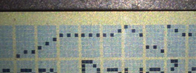
    Using a text-lcd to draw a graph...

    The first discontinuity is maybe a math bug... The second is just random leftover from old code. In all, this might could work.

    Of course, the HD44780 only has 8 custom characters, but A) technically, that's all I need to plot 8 data-points, and B) I've a few ideas to squeeze more outta it if I need to.

    For this proof-of-concept, though, I'm quite pleased with how it looks. I was somewhat-concerned it would be too sparse to recognize as a graph, or that it would be hard to see. Not bad at all!

  • Well that didn't quite go as planned..

    Eric Hertz08/31/2022 at 10:49 0 comments

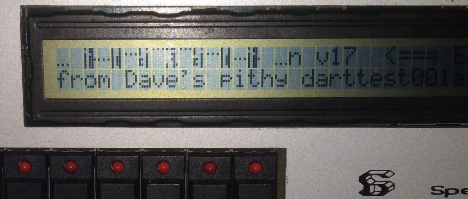
    Dave's Pithy DART test program is now a bootloader/BIOS of sorts...

    With a little work, it loads a main() function compiled in sdcc.

    Previously, the ihexFlasher, which has had a little improvement, and is being used to test my LCD-Grapher (shown above).

    It's supposed to display 8 custom characters, the first is "OK", followed by 7 steps up and seven back down.

    Since OK is missing, I think somehow the second custom character overwrote the first.

    Interestingly, just before I coded this up I happened upon something I never recall seeing previously, about these displays, nor ever had trouble with... Allegedly the BUSY flag actually deactivates after data's written, but 4us *before* the address-increment occurs(?!)

    I suppose this could explain it... combined with maybe a few timer-interrupts slowing it down sometimes, and not others...?

    Too tired to look into it right now.

    Really, I mainly just wanted to see if a graph would look OK if I skipped every-other pixel, so it wouldn't have solid lines broken between every five pixels. Which, I think, would look especially bad if, say, the graph needs to be four pixels per step. I think skipping pixels should work. It'd be two pixels per step, then, and no breaks.

    ...

    I kinda dig the weird characters that resulted from the glitch... Looks like some ancient script. It always amazes me there can be patterns in a measly 5x7 grid that I haven't seen before.

    ...

    Oh, the now-pithy ihexFlasher...

  • Beat...

    Eric Hertz08/17/2022 at 04:52 2 comments

    Wrote up a draft what seems quite some time ago, basically about this same thing... Why not just post it? Dunno, maybe my brain's in a slightly different place, now, and I can go back and compare...

    ...

    I guess it boils down to "I'm beat."

    I mean, it seems fair, considering this project was pretty much the only thing I was doing for months, aside from... well, Let's just call it a fulltime nonpaying job, with a lot of overtime.

    I'm not exactly incapable, now, of seeing the project-ideas I had for this, the ideas which the ihex-flasher was to enable... the ideas I'd built-up all last year while working on #Vintage Z80 palmtop compy hackery (TI-86) ... but I sorta can't see them, either.

    I guess the question, somewhere, was what was the goal...? And, well, I really dunno.

    Flashy doodads were supposed to be the icing on the cake after the ihex-flasher, but then my flashy-doodads turned out to be a huge amount of work; 3.3V level-shifters aren't so bad, unless they need to be wired to FFC connectors, and so-forth. I've, unquestionably, done these sorts of things with point-to-point wiring before, was worth it, then... but right now just doesn't seem that way.

    Oh, I remember... One idea was printing highlighter-ink in red and green in a grid on a transparency, and backlighting that with blue-LEDs... Turning a B/W display into color... Actually, that's kinda intriguing just to see how it looks. But, yeah, gotta either get a color inkjet that has highlighter cartridges, or hack mine...

    I had actually looked into that a little, way-back... the oldschool B/W bubblejet I've got has such a standard cartridge that they can still be bought, and the service manuals actually show the pinouts and timing(!). Turns out the color cartridge is nearly identical, they basically just rewired a couple pins and divided up the 64 B/W nozzles into 48 total for CMY. It'd probably be an easy hack.

    Top that off, when I worked on #The Artist--Printze , one of the important factors was modifying the driver because, at the time, I thought the cartridges were surely too old to still be available... Printze's cartridge was empty and easily hadn't been touched in twenty years. After refilling it with ink from the cheapest cartridge I could find locally ($5), it turned out that the first 16 nozzles were non-functioning. So, I modified the driver to print with the 48 remaining.

    HAH!

    So, I guess, it'd be pertydurnsimple to go from there to use that color cartridge with its 48 nozzles.

    Heck, I wouldn't even need to make the driver color, knowing which nozzles to use. Hmmm....

    Oh, wait... no... dropping different colors in the same row means printing that row three times... heh. Well, I also have a pretty thorough understanding, now, burried in there somewhere, of how to control it manually (via my own software)... Which, actually, might be better, as I have no idea whether the fluorescent ink drops would be thick nor dense enough to convert all the blue.

    Heh. Well, this is *sorta* a welcome aside from the weeks of "beat."

    I dunno, it seems a bit crazy. 

    And, well, the idea of a fluorescent display with a blue backlight, it turns out, was actually patented, many moons ago.

    And, dagnabbit, look at those mofos on the youtubes... I didn't even choose to make a "short" of the next vid, wherein I had three colors, I even tried everything I could to *not* make it a "short"... Now analytics says most its views were from "the shorts feed" (youtube *seriously* shared *that* with *everyone*?!), and I got friggin downvotes! I feel kinda bad right now, TBH. Sheesh! Youtube is a friggin' bully, trying to draw in other bullies! Good thing I've got 30-some years of slightly thickened skin, I wonder what the next generation gets out of this!

    .

    Anyhow, I know it'd be very different from "the real thing". Real color LCDs put the filter *inside* the glass panel next to the liquid crystal so that the viewing-angle doesn't have to be *perfectly* head-on,...

    Read more »

  • ? Spectradata SD-70 in the wild ?

    Eric Hertz08/05/2022 at 20:07 0 comments

    Did You Buy it?

    As far as I've been able to gather from the interwebs, only two of these machines may've ever existed...  

    I'd been contemplating buying the second to keep them together, and also maybe to find out a few unknowns. (E.G. What is that AMD chip's part number? Did the other unit have the GPIB chips installed? Did they hand-etch the front-panel board on both of them? Were they built at the same time, e.g. for the same customer, or...?)

    Anyhow, if you bought the second one (or just happen to have another, or know anything about it) it would be great to hear from you!

    eric -> wa -> zhu -> ng

    Via:

    gm -> ail

    Of the dotcoms

    (Why can't I unbold that?!)

    I'm curious what others' interests may be, or what they may do with it... Reverse engineering endeavors of their own? Actually use it as intended (Do you know anything about the equipment it attaches to?) Figured it was a great price for a project-box, a bit like I did at first (wanna sell its guts?)? Did you find it through the logs, here? If you put anything on the net about it, I'd be happy to put some links in here. So-forth.

    For the search engines:

    spectra data SD-70

    Spectradata SD70

  • The Rominator: Overkill maybe.

    Eric Hertz08/01/2022 at 09:11 0 comments

    It works!

    As I recall (shyeah right... like I'mma go back and read all that!) the ordeals of the last log basically amounted to really weird luck prompting me to realize some variable initializations never occurred.

    After I fixed that, it all seemed to work as-tested on a PC, up to the point of actually performing the Flash-writing, which couldn't be tested yet because the SD70 has separate chip-selects for each of its 4 16k memory-sockets, and the Flash I've been using in the first socket requires an "unlock" procedure that requires accessing 32K of its address space.

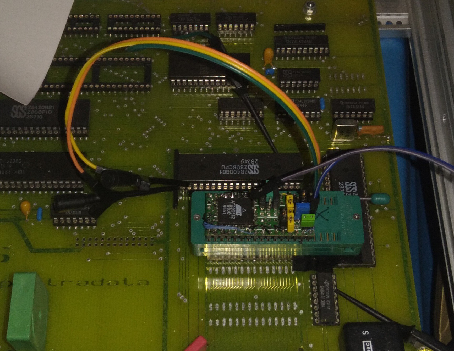
    The plan since I started this flash-endeavor has been to have a jumper on "The Rominator" which selects one of two 16k pages to boot from. Simply switch the jumper to boot into the firmware-uploader, switch it back to boot into the new firmware.

    I went a little overboard because, well, the simplicity of the idea grew in complexity quite quickly. 

    E.G. the SD70's ROM sockets obviously don't have WriteEnable... So I need a wire and test-clip for that. 

    The A14 line is pulled high, as for smaller ROMs that pin has another purpose, so I already needed/had a jumper to disconnect it and a resistor to pull the chip's A14 low... But now I need a way to actually control it (for unlocking the flash-write) AND a way to invert it (for selecting which image to boot from). OK, three jumpers. 

    The Output-Enable is connected to the Chip-Enable (maybe it decreases access time?), but the flashing procedure requires /OE to be high. I ran into the same with #Vintage Z80 palmtop compy hackery (TI-86) , so if I want to use The Rominator in another project, I might benefit there, as well, from now another jumper and another test-lead. 

    The Chip-Enable, now, has to have *two* inputs ORed together, and another test-lead.

    Surely I'm forgetting something.

    While I was at it, I decided to give A15 similar treatment as A14... Now the original "stock" firmware can be booted via jumper, as well. Oh, right, and A15 is also pulled high at the socket, so had to have a jumper and pull-down.

    OK...

    Now, I didn't have much space left on the board, so was quite pleased to find an SOIC 74F00 in my collection... Until I realized 100k pull-down resistors would not be anywhere near spec (600uA out of the input, 100kohm, 6V?!). Alright, well, at that point I was beat (how long has this been, a week?!) So I decided I'll just require that A14 and A15 are always driven by either an output or by power rails. A14 already has a header, now, for a test-lead, but I didn't do that for A15, so I fudged another header-pin next to the jumper for grounding.

    Heh. This has gotten crazy. BUT: The previously-unnamed Rominator was of great use in #Improbable AVR -> 8088 substitution for PC/XT , and now again in this project, so I guess its new versatility could be useful in another project down the line.

    (Did I mention I spent Hours fighting my printer several weeks back so I could print its schematic small-enough to strap to it? I guess I'll have to do that again. Thankfully this time I think I know why it was so difficult last time. Though, this time there's quite a bit more information to fit in there).

    Oh, right... So I finally put it in the socket for the first time in what seems like forever (I seriously expected this to take an afternoon, not DAYS) and it still booted the old firmware just as I expected... But, it didn't boot all the way... What?

    Took me a while to remember that ordeal of the last log... right, trying to hunt down incredible odds led me to load an earlier version. So, while flashing the latest version, I also flashed the stock firmware at 0x8000... Tried the latter first. No problemo. Tried the firmware-flasher next at 0x0000, burnt an old test-program to 0x4000 (over the serial port!). Not a hiccup. booted from that for some pithy nostalgia from who can remember how many weeks ago...

    Holy Moly, I can In-System-Program, now! And I can...

    Read more »

  • Merging C and ASM...

    Eric Hertz07/23/2022 at 06:32 6 comments

    Next-Next and Next-day brief Updates at the end...

    ...

    I am by no means experienced nor knowledgeable in this realm... 

    I have done a bit of inline asm in my otherwise avr-gcc progects. But this is very different.

    Here we have a booting system written in assembly, and I plan to make a bootable utility in C that makes use of the initial-setup and functions that assembly-code provides. In a sense, I'll just replace its "main loop" with my own.

    Initial experiments were very promising. I wrote a small main()-like function in C, wrote a "void function(void);" *declaration* (not definition) for one of the assembly functions, called that function from mine...

    From that alone (not even "including" the original assembly file in any way) sdcc gave me assembly-output that was *easily* modified in such a way that I could little more than copy/paste its output into the original assembly file and run my code as though I'd written a new function in assembly in the original.

    Basically, sdcc's assembly output did "calls" to labels, and those labels just happened to not exist within its awareness... and it didn't seem to care.

    Which was *great* because when I pasted that output into the original assembly file, those labels now were available, and my assembler replaced them with the appropriate 16bit addresses. Just like assembly does.

    I guess I'd expected sdcc to croak on the missing labels long before actually outputting a usable assembly file.

    So... Awesome!

    ...

    So then I bit off more than I could chew.

    Wrote the entire utility in C, tested it with gcc as best as possible all along the way. Finished it, finally, today...

    Then... yeah.

    OK, so the big thing that ultimately stopped me from proceeding with my original plan (of copy/pasting sdcc's output into the original assembly file, then hand-modifying it as-necessary) is the fact that the sdcc output uses the same label-names in all functions. e.g. "00104$" which resulted in my assembler's complaining of duplicate labels 69 times. I *almost* considered hand-changing them until I realized it looks like it only complains about the first duplicate of each... Heh.

    So then, obviously, just throw the thing into sdcc's assembler, instead, right? But apparently *that* didn't like the original assembly in an entirely different and equally difficult to repair way: Apparently it's so low-level that it doesn't handle things like "equ"... which would be a tremendous feat to remove all instances of. Heh.

    Again, I'm no expert, maybe it was just a matter of find/replace... but this came after quite some effort dealing with many other incompatibilities, e.g. "immediate values" are prefixed with # in one, but not the other...

    So, finally after much "hand-jobbing" I decided it was time to throw up my hands and come up with another way.

    Now, I should probably interject that obviously there is some "right" way, otherwise we wouldn't have many of the fine things we have... I imagine "the linker" is a big part of it. I have history with that beast that prevents me from preferring trying another go at it over, say, hand-editting 69 labels.

    But, I think I came up with another solution, which actually should be easier... just modify the original to call some specific address, say near the end of the ROM. Assemble that in the usual way. Then modify sdcc's assembly-output with actual addresses instead of labels pointing to the original code. There's only three functions and one buffer to be loaded into RAM. Four addresses to hand-enter. Oh, and a .org at the beginning of its output to somewhere after the original's.  And, finally, add a .org at the decided-upon jump-to-address, with a jump to my main(). Then, of course, use sdcc's tools to compile that, as though it was its own completely standalone thing. Merge the two ihex files, and we're done! Scripting that whole process should be easy-enough, too. And it allows for keeping the two codebases separate, which has...

    Read more »

  • To Xon or to Xoff, that is the question.

    Eric Hertz07/16/2022 at 03:21 10 comments

    Apparently the answer is "Just don't".

    I'm too tired of the whole scenario to go into it. But let's just say that some once-standards seem to have been brushed-aside in really awful ways that make me lose faith in far too many things.

    I commented on it in a previous log... Basically having come across several linux mailing list archives of folk submitting patches to support Xon/Xoff for various USB-Serial dongles (whose chips actually support it at the hardware level!) and yet those patches being abandoned for essentially "most USB adapters don't support it" despite the fact the drivers claim to. AND, the fact that the stty-default, when you plug those dongles in, is to claim that it's enabled. Worse than that, there were even folk submitting patches to at least give a *warning* to the user that xon/xoff isn't supported, and even *those* patches were seemingly driven out of the kernel.

    I also found this: https://hackaday.io/project/16097-eforth-for-cheap-stm8s-gadgets/log/49010-a-serial-terminal-for-linux-with-working-xonxoff

    Wherein Thomas went into a lot of digging to figure out (and share) where the hurdle exists...

    ...

    This is now the /third/ such thing I've run into that was basically once such a standard as to be in nearly all the great references that were de-facto reading for generations of folk using RS-232.

    The first was long-enough ago that it's a bit muddled in my mind. As I recall it had to do with counting edges on handshaking lines. The great example I recall of its disappearance (and yet claiming to still exist at the driver level) was a GPS standard which is often used to synchronize systems' realtime clocks, e.g. data-logging systems which aren't able to connect to the internet... Like what? Think trailcams if you can't imagine scientific research. Isn't that pretty much *exactly* what linux was once so great for? It blew my mind how, frankly, rude folk were toward this guy, and indirectly toward the entire scientific community, for not using things "the one way" "everyone" does. Goes ENTIRELY against everything that I thought made linux great.

    ....

    The second was custom baudrates.

    The Standard, for generations, was to assign your custom baudrate to 38400baud. The Idea being that nearly every terminal application, or serial application, supports selecting that baudrate from a list, whether supplied by the OS, or in a list in the program itself. Thus nearly *every* serial program could make use of a custom baudrate, as long as you configured it before loading the program.

    Yes, at the driver-level that might mean running a custom program to actually set the appropriate registers, but even that had become commonplace enough that linux has provided the appropriate and common tools to do-so, for decades; one for countless different serial chips. EXCEPT. USB-Serial dongles. Why? Searches of mailing lists result in pretty much the exact same sentiment, over and over... "Most USB serial chips don't support it" which, frankly, wasn't even true, in my experience, decades ago, and far less today. AND, again, the drivers seem to allude to the support being there, and configuration-programs give no warning it isn't.

    Again, this isn't just about buying cheap hardware, we now live in an era where USB is darn near the only reasonable option. This is downright absurd. Their arrogance is affecting everyone from kids learning Arduinos to government-sponsored research endeavors. Nevermind the folk who put tremendous effort into making great software that stood the test of time.

     And, nevermind the folk who wrote excellent resources/reference-manuals that we still are referred to as "The Best" now in an era where those things we learned are now just flat-out lied-about still existing in our configuration utilities and drivers.

    ...

    The third is XON/XOFF, and again, frankly, I'm still seeing red that I spent a week or more implementing that in an embedded project *because* stty reports Xon/Xoff is enabled As Default...

    Read more »

View all 28 project logs

Enjoy this project?

Share

Discussions

wmeyer48 wrote 06/21/2022 at 18:06 point

Long ago and far away I knew a guy who was developing a CPU in-circuit emulator. Too long now to recall whether he used a Kaypro or an Osborne. No matter. He coded it all in hex. Seriously. I don't remember whether he had a name for it at that time. Would have been roughly 1983.

  Are you sure? yes | no

ziggurat29 wrote 06/21/2022 at 19:50 point

ICE, ICE, baby! A big hit in the 80's, before all that funky JTAG jive!

  Are you sure? yes | no

Eric Hertz wrote 06/21/2022 at 21:08 point

Cool, Inspired some ramblings on an in-circuit programmer (not emulator) I'd been mulling-over. There's sure to be a log-entry on it later. Sounds like a smart guy to befriend back in the ol' wild-west of computing. Thanks for sharing!

  Are you sure? yes | no

Similar Projects

Does this project spark your interest?

Become a member to follow this project and never miss any updates