Eric Hertz
-
Taking a step back...
12/08/2016 at 23:27 • 0 commentsThe physical-world gets in the way of the mathematical/hypothesis I had in mind... Though it is interesting to experiment with, as is.
The basic equations, again, were something like:
PowerN = (desiredPositionN - actualPositionN) * constantN
and
desiredPositionN = actualPositionM * ratioNM
--------
Unexpecteds:
E.G. DC motors have poles... yahknow? Certain positions in the rotation where the same amount of voltage in doesn't result in the same amount of torque, due to, I guess, things like the air-gap between the windings and the permanent magnets, etc.That feeds back into the system!
E.G.2 There may be some "slop" introduced by the motor-driver[s]... e.g. short pulse-widths may be appearing more as a triangle-wave rather than a rectangle, due to things like output rise/fall times. E.G. two unloaded motors; one requires very little effort to turn (and the other follows nicely), but turning the other takes a tremendous amount of force to rotate before the first begins moving, and once it does, the effect on the second is a noticeable *grinding* feeling (as the first motor advances one tick at a time).
E.G.3 Accounting for that "slop" by changing constantN makes it hard to turn *both*...
----------It's definitely interesting to experiment with, worthy of further exploration...
Here's an interesting one:
Say you change the "gear ratio" (ratioNM = 1/ratioMN = 1/4)... Turning motor N, you can actually feel when motor M advances, once every 4 encoder-ticks.
-------
Interesting, for sure. But, I think the math needs some work, before it would be usable for this drill press system. Maybe higher-resolution encoders'd help, as well. PID, maybe. Plausibly additional information (than just encoder-ticks) might be useful e.g. current-measurements... Probably would be aided *dramatically* by using identical motors/drivers. So, it's a bit on-hold, for now... I think I'm at something like 750Bytes.
-
int32 multiplication = NOOOOOO!
12/07/2016 at 01:02 • 7 comments#define MOTOR1_KP_SHIFT 0 //kP = 1 #define MOTOR2_KP_SHIFT 3 //kP = 8 void pwmify(motor_t *motor) { //Assuming "power" is > 0 when moving toward desiredPos>0 from 0... int32_t power = (motor->desiredPos - motor->actualPos); //power *= (int32_t)(motor->kP); //!!! //This ONE multiplication takes about 100us! //Regardless of whether kP is 1 or 8 //Despite kP being 'const' //And replacement reduces codesize by nearly 400B // (Probably due to _mult_i32() not being linked in?) //NOTE: The kP "multiplication" replacement //is now handled after the following //(Alternatively, I suppose, I could assume the desired/actual // difference should never be greater than an int8_t...?) if(power >= 0) motor->dir = 1; else { motor->dir = -1; //unsign it! power = -power; } uint32_t uPower = power; //The kP multiplication is now replaced with this: //NOTE: SIGNED-SHIFT is undefined per C's specs (as I recall) // So this needs to be AFTER the sign is removed. if(motor->num == 1) uPower <<= MOTOR1_KP_SHIFT; else uPower <<= MOTOR2_KP_SHIFT; if(uPower > 255) uPower = 255; motor->pwm = uPower; } -
It Works-ish!
12/06/2016 at 18:05 • 0 commentsActually wrote this before the log "Taking a step back...", but didn't submit it for some reason until now (12-15-16)... it's been sitting in a "tab" for quite some time...
----------------
So, I've just connected two motors with encoders and a really simple feedback system for each, and between the two. Basically little more than,
power[n] = (desiredPosition[n] - actualPos[n]) * Kp[n]
anddesiredPos[n] = actualPos[m] * PosRatio[nm]
And the results...?
I should just throw up some video... but it's *really* interesting to play with.
Messing with the ratios, it's kinda like having gear-reduction (or the opposite) between the two shafts. Except... SPEED-wise, it's like gear-reduction/increasion(?), but *torque-wise* it's like the exact opposite.
I dunno if I've got the ratios wrong or if it has something to do with the motor-drivers, or the motors, or the math, or what...
But just think about that for a moment... I mean, we've all a pretty good idea about what it's like to spin a tiny gear, and have it turn a larger one... (think of a bike).
Real gear-systems take a tiny bit of force on a small gear, but a lot of turning, to rotate the big one a little bit.
But in this case what's happening is a LOT of force and a lot of turning to rotate the big gear a little bit.
And equally-weird a tiny bit of force and a tiny bit of turning to rotate the big gear, causing the tiny gear to rotate *a lot*.
It's like gravity turned upside-down, or something... or one's first experience with cornstarch and water ("non-newtonian fluid"). A weird mind-bender.
---------
Force-feedback...? Yeahp, it seems to exist.
Unexpectedly, I'm feeling the additional force it takes to change the position of the motor slightly when it approaches a pole... and various other factors of the motors themselves, the resolution of the encoders, and more that has nothing to do with external loading.
This is some interesting shizzle... and also a bit dangerous. It's only drawn a tiny bit of blood so far.
But I'm quite tired, so we'll have to do more another day/hour.
-
No Longer Locked-Antiphase -- SeemED Good
12/05/2016 at 12:56 • 0 commentsProbably burried in the last log are a few thoughts...
Locked-Antiphase PWM is difficult to set up with a "reset-default". How's one going to generate a 50% duty-cycle to stop the motors when the uC is being programmed and its PWM outputs are floating...?
Among other reasons, the solution I chose was to forgo Locked-Antiphase, in favor of two inputs, one for PWM and one for DIR.
If you think about a regular H-Bridge, there's two inputs and two outputs. Driven digitally (high or low) the outputs essentially follow the inputs. A logic-high on one input will result in that side of the motor-winding being driven with the high motor-voltage.
So, then... one way to drive those two inputs is to choose one input as DIR and the other input as PWM. (Annoyingly, when DIR is reversed, the PWM value must be inverted, e.g.25% duty-cycle for 25% power-output needs to be 75% duty-cycle for 25% power-output. But that's not a big deal).
So, then... for a "reset-default" that won't cause my motor to spin at full-speed when the inputs float, simply add pull-resistors to the inputs... both to the same level.
SIMPLE!
Coded it all up, less than 100 extra bytes... Awesome!
---------
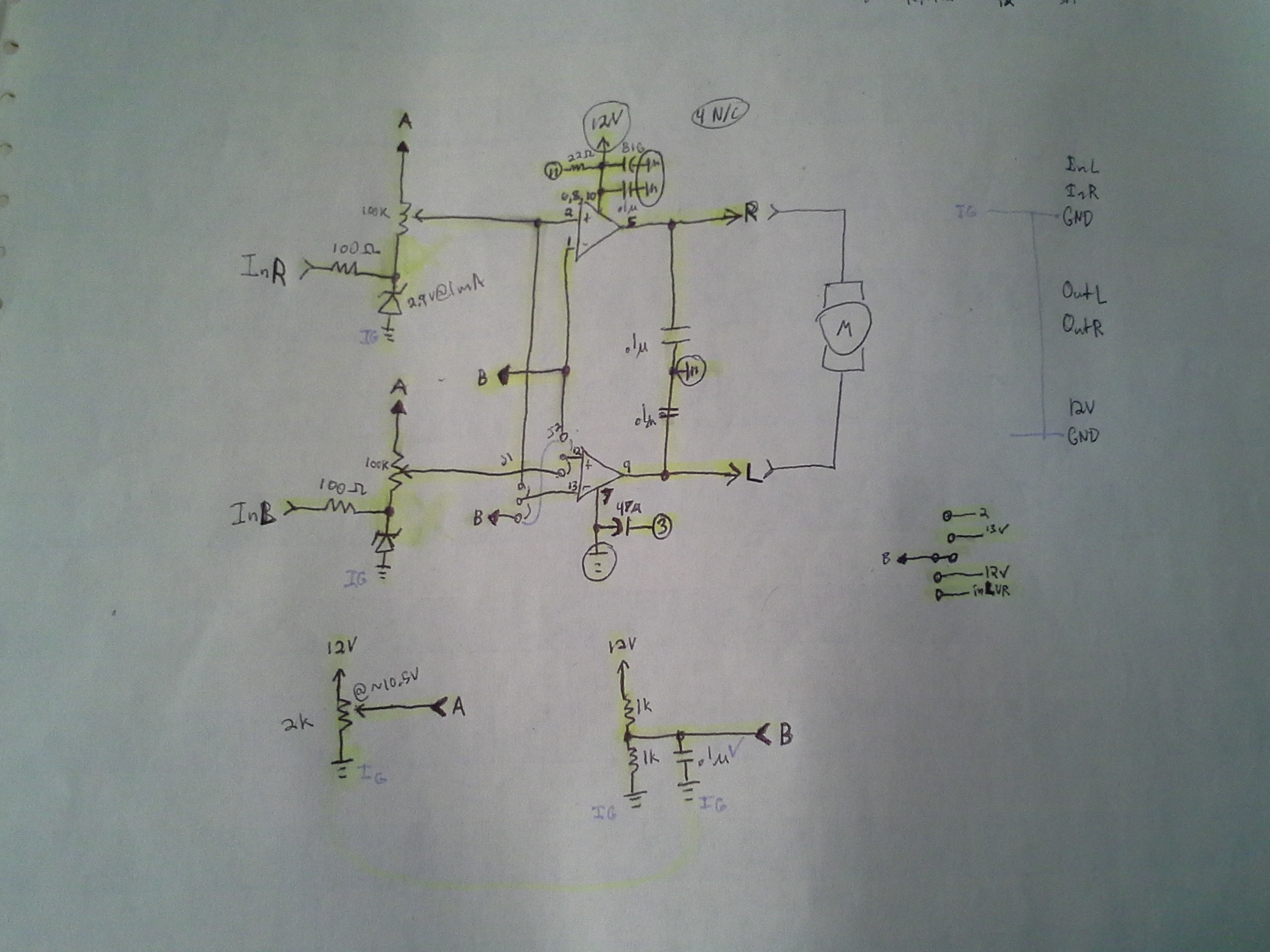
Yeah, but... My motor-driver/H-bridge is a bit of a wonkey-experiment...
![]()
High-power op-amps (audio-amplifiers) are used as, essentially, comparators. The inputs are analog, not digital, and they've comparatively low-impedance.
Reasonable-valued Pull-resistors, alone, probably won't drive enough current to do this.
OTOH, took me way too long to figure this out, but *maybe* I can change the values on the 100K potentiometers such that the "floating" inputs would result in high (or low?) output.
Anyways, I'll have to look into all this a bit further. I still think pull-resistors, at the uC-output, are a good idea... (This isn't the only motor-driver I might use, and it's a separate board). So... ToPonder, but not tonight/this-morning.
-
BIG WARNING + schematics...
12/05/2016 at 09:33 • 0 commentsBIG TODO/WARNING:
WORKING WITH MOTORS CAN BE DANGEROUS: BE CAREFUL!!!
-------------------------
Realized upon drawing up the schematic (referencing an old one), that there's a dangerous problem with how I intend to drive the motor... There are dangerous cases where the motor will run at full-speed/power, that have nothing to do with my programming-skill!
-------------------------
Specifically, in this case:
I plan to use Locked-Antiphase PWM control of the motors...
(Locked-Antiphase is where PWM-value of 0% results in full-power in one direction, 100% is full-power in the other direction, and 50% duty-cycle stops the motor).
Can yah guess the problem...?
When PROGRAMMING (or in reset, or worse, if the uC fails), the pin driving the H-Bridge's PWM-input will be floating. It *might* float near ground or near V+... Thus, when programming, the motor might run FULL POWER/SPEED in one direction or the other!
Previously, I used separate outputs for PWM and Direction, so it was easy to tie a pull-down resistor to the PWM pin, such that when programming (or the pin was otherwise floating), the motor-driver would be disabled. Not the case with Locked-Antiphase. WHAT TO DO...?
This is DANGEROUS in this case!
- The drill-press motor could slam into either end, at full-power.
- Don't have your fingers anywhere near the moving parts when programming!
- Don't have anything on the work-bed that might fly across the room!
- Don't have a drill-bit in the chuck that could break and fly across the room!
- Make sure your system is strong enough to handle these sorts of disasters!
- The handle/lever-motor could slam into either end, at full-power!
- (Is there an "end-stop" in this design? Or will it spin around at full-speed?)
- Don't have your fingers anywhere near the moving parts when programming!
- Don't have anything near the lever's path that might fly across the room!
VERY IMPORTANT when working with high-torque motors:
(This list is *by no means* all-inclusive! Think For Yourself and Do Research, and even still, consider yourself a contender for The Darwin Award!)
- ALWAYS install an emergency-cut-off switch!
- This should *PHYSICALLY CUT THE POWER TO THE MOTOR* not go through software or even the H-Bridge
- This should have a large easy-access button which can *only* be turned-OFF in a frantic reach
- Install end-stop detectors!
- (AKA "Limit Switches")
- Do-so at *both ends* *even if* you don't need to *measure* the end-stop positions, nor move to 'home'
- These should *physically cut the power* to the motors, as in 1a.
- Consider what happens when the software/circuitry is non-functional, and design with this in mind!
- This can occur e.g. when:
- The microcontroller is in reset (or programming, or failed due to unintentional shorting, static-shock, etc.)
- power is lost to the controller-circuitry, but high/motor-voltage remains
- Install pull-resistors
- Install a watch-dog *circuit* as well as watch-dog *software*
- I'm losing steam. Think about that Darwin Award.
- This can occur e.g. when:
- DURING software-devel and/or during circuitry-assembly:
- It's *EASY* to accidentally reverse-polarity either the motor or the encoder... Either one could result in the motor attempting full-power back to its desired-position!
- It's *EASY* to accidentally reverse-polarity either the motor or the encoder... Either one could result in the motor attempting full-power back to its desired-position!
-------
So, I'm working on 3b...
Problem is, I'm out of motor-drivers with PWM/DIR inputs.
In fact, I'll be using two different motor-driver/H-Bridges for this project, and planned to drive them with the same signals...
[Insert a lot of rambling, here, and maybe a solution or two I hadn't foreseen before writing this]
(I'd been working on a third motor-driver circuit, for a separate project. This driver one *only* has locked-antiphase as an option... Funny it hadn't occurred to me, until now, the potential for Darwin Award Winnings!)
The first H-Bridge, in this project, has the PWM/DIR option as well as Locked-Antiphase, and ALSO has a BRAKE input. So, with locked-antiphase, I can pull its BRAKE pin *high*, and floating won't be a problem.
The other H-Bridge also has Locked-Antiphase as an option... so that seemed like the obvious choice. But, of course, I've yet to think about how to do a simple hardware-hack to assure 50% duty-cycle when that output's floating (maybe a 555? Maybe I should put that *on* the motor-driver circuit-board? Maybe just a relay that cuts the power...?).
This second H-Bridge *also* has the option to be controlled with a third PWM-mode... I don't know what it's called, but you basically tie one input high/low, then PWM the other input, for one direction. For the other direction, you *swap the pins*.
(Rereading: Wait a minute... can't I just use the high/low input as a direction-input??? HMMMM)
This second option is a bit more difficult on some uC's where PWM-outputs are limited in numbers. So, I tend to avoid using it, and, again, it's not an option with the first. The gist, then, would be to use *two* PWM-outputs, and drive one at 0% or 100% while driving the other at your desired duty-cycle.
The ATtiny861 I'm using (due to supplies-on-hand) has several PWM outputs (six! sorta) so that's not a *huge* limitation. Those outputs are in pairs, "complementary" outputs, where essentially one is the opposite-polarity of the other, which doesn't help the "floating" case...
(Rereading: or does it...? Sheesh.)
Though, there are a few more options than merely complementary-outputs (including Dead-Timers, which assure they don't swap-signs at the same instant, and a PWM6 mode designed for BLDC control). So, there're definitely options... but it's a bit wasteful of a design if I decide to use less-capable uCs for later projects.
I'll have to think about this some more... If the high/low input could be used as a direction-input... or even if I use the complementary outputs... then all I need to do is pull both pins to the same value (via resistor). Bam.
The first case (high/low input = DIR) *essentially* PWM/DIR input, except that when you swap the DIR sign, you also have to invert the PWM duty-cycle (right?)... Might go with that one... Got some thinking to do...
----------
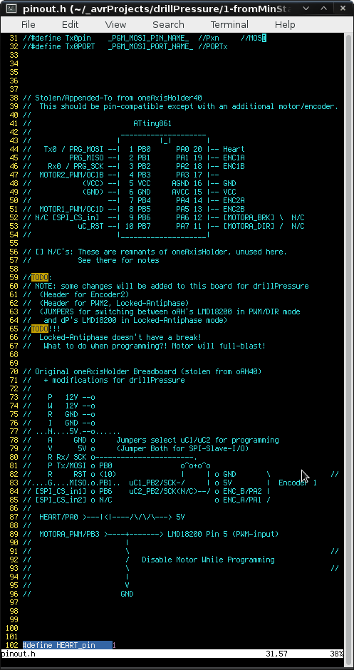
Oh, "schematics"... Not yet complete...
![]()
Apparently I'd been *using* the "oneAxisHolder" off-n-on for *various* projects, for years... and never drew up schematics/pinouts in a single location... Was "fun" digging through all the source-code and tracing it out on the proto-board to figure it all out again, years later. So, what you see above is basically that, with some TODOs for this new project, because, mostly, building an entirely new circuit-board isn't really in my mindset, lately.
So, in figuring out whether the "second" motor-driver will work with pseudo-PWM/DIR, this may be helpful... from my ol' #Random Ridiculosities and Experiments wherein I'd been using an audio-amplifier chip as a motor-driver.
![]()
(The "Locked-Antiphase-Only" circuit I'd been working on was based on the TA8251AH 4-channel BTL audio-amplifier... And, lo and behold, it has both a "standby" input and a "mute" input, so pull-resistors should work!)
- The drill-press motor could slam into either end, at full-power.
-
782 bytes - untested but complete I think
12/05/2016 at 02:12 • 0 commentsAlright, I think it's complete... Not yet tested (got some soldering to do).
760Bytes in .text and 22 bytes in .data.
------
Seems like I'm doing all sortsa things in weird-for-me ways, lately.
Usually I'd take a much more vigorously step-by-step approach; code up a small part, test it, code up the next...
This time I wrote the whole thing without testing any of it. OTOH, I've done the vast-majority of this stuff before in other projects. So, we'll see.
I wasn't *planning* on PID, nor on implementing "software" return-spring/felt-pads/gravity-resistance... but it looks like there's enough code-space and time remaining to at least attempt 'em.
Though they're not nearly as intuitive to me, so I might take on another project, instead.
-----------
This is something I've been meaning to attempt for quite some time... though, so it'll be interesting to finally see how it functions. Without the drill-press nor gear-reduction, with just two motors sitting upright on the desk, It should essentially feel like I'm spinning two knobs which are linked via pulleys and rubber-bands. Could be quite an interesting tactile-effect, and something that could be useful in other projects, as well.
-
coding...
12/01/2016 at 17:41 • 0 commentsI have no idea whether this'll fit... but I think I've done the biggest portions, thus-far (int32 math!), and we're fitting in 542Bytes...
#include <avr/io.h>
#include <inttypes.h>

typedef struct motorThing
{
   int32_t desiredPos;
   int32_t actualPos;
   uint8_t pwm;   //Assuming PWM=128 ==> 0 power
                  //PWM=0 ==> Full-Reverse
                  //PWM=255 ==> Full-Forward
   uint8_t kP; //Ideally, this'd be constant...
} motor_t;

motor_t motorA = { 0, 0, 0, 1};
motor_t motorB = { 0, 0, 0, 1};

uint8_t pwmify(motor_t *motor)
{
   //Assuming "power" is > 0 when moving toward desiredPos>0 from 0...
   int32_t power = (motor->desiredPos - motor->actualPos) * motor->kP;

   //Using whatever-it's-called PWM, where 0 *power* = 128 *pwm*:
   if(power > 127)
      return 255;
   else if(power < -127)
      return 0;
   else // -127 < power < 127
      return power + 127;
}


#define posRatioA   1
#define posRatioB   1

#define HEART_pin    1
#define HEART_PORT   PORTB
#define HEART_PIN    PINB
#define HEART_DDR    DDRB

int main(void)
{

   //TODO:
   // Initialize the timer(s) for PWM output:


   //Indicate the loop-rate via an LED...
   // (Use a 'scope to check it)
#warning "VERIFY! 1 = output?"
   DDRB |= 1<<(HEART_pin);

   while(1)
   {
      //As long as this LED toggles at a rate faster than our encoders can
      //increment, we don't need to use interrupts to handle the encoders
#warning "VERIFY!"
       if(HEART_PIN & (1<<HEART_pin))
         HEART_PORT &= ~(1<<HEART_pin);
       else
         HEART_PORT |= (1<<HEART_pin);

      //TODO:
      // Read the Encoders!

      //Tie the two motors together...
      motorA.desiredPos = (motorB.actualPos * posRatioA) / posRatioB;
      motorB.desiredPos = (motorA.actualPos * posRatioB) / posRatioA;

      //Determine the new PWM values for each motor
      motorA.pwm = pwmify(&motorA);
      motorB.pwm = pwmify(&motorB);


      //TODO:
      // Output the PWM values to the OCR's

   }
}
Seems doable....
------------
HOWEVER:
The optimizer's pretty durn smart...
And it might just recognize that the math here doesn't result in any *changes*... Since... The encoders aren't yet implemented. So, it's *plausible* that once this thing gets some encoders-involved, things might increase quite a bit. A *reasonable* test would be to create a function to "pretend" to set encoder-values, and set those variables "volatile"... but of course, I'm not capable of thinking in that realm, right now...
----------
It (mah-brain) is, however, capable of adding "volatile" to "actualPos" in the struct...
And the result is *exactly* the same, size-wise...
Which... I dunno whether to be happy about, or confused about.
On the one hand, that might just well mean that I don't have to worry about code-size increasing dramatically when I add the encoder-handling...
On the other hand... if the optimizer's not capable of recognizing that actualPos doesn't change... (from 0), then ... am not nearly as impressed (maybe even somewhat "disillusioned"?) by the optimizer's abilities.
On the third hand... if the optimizer *completely disregards* the volatile statement, in this case, it might mean that it's recognizing that the value *still* isn't changed, despite being marked volatile, which might mean that I've got *a lot* to worry about, once I introduce the encoder-handler...
Oy!
-----------
Or there might be a fourth-hand, which I can't quite comprehend right now...
THIS results in 562 Bytes... that's only 20 more than previous... and This should Guarantee that "actualPos" isn't being presumed to be any particular value, which should, therefore, assume that ... no, I don't *call* the function. WHOOPS
-------------
OK...
HERE WE GO...
I think this be right.
Now we're at 610 Bytes.
#include <avr/io.h> #include <stdint.h> typedef struct motorThing { int32_t desiredPos; volatile int32_t actualPos; uint8_t pwm; //Assuming PWM=128 ==> 0 power //PWM=0 ==> Full-Reverse //PWM=255 ==> Full-Forward uint8_t kP; //Ideally, this'd be constant... } motor_t; motor_t motorA = { 0, 0, 0, 1}; motor_t motorB = { 0, 0, 0, 1}; uint8_t pwmify(motor_t *motor) { //Assuming "power" is > 0 when moving toward desiredPos>0 from 0... int32_t power = (motor->desiredPos - motor->actualPos) * motor->kP; //Using whatever-it's-called PWM, where 0 *power* = 128 *pwm*: if(power > 127) return 255; else if(power < -127) return 0; else // -127 < power < 127 return power + 127; } #define posRatioA 1 #define posRatioB 1 #define HEART_pin 1 #define HEART_PORT PORTB #define HEART_PIN PINB #define HEART_DDR DDRB void updateActualPos(motor_t *motor) { #warning "THIS IS A MAJOR HACK!" //Just trying to insert *something* that the optimizer shouldn't //optimize-out... THIS IS NOT VALID DATA!!!! motor->actualPos = PINA; } int main(void) { //TODO: // Initialize the timer(s) for PWM output: //Indicate the loop-rate via an LED... // (Use a 'scope to check it) #warning "VERIFY! 1 = output?" DDRB |= 1<<(HEART_pin); while(1) { //As long as this LED toggles at a rate faster than our encoders can //increment, we don't need to use interrupts to handle the encoders #warning "VERIFY!" if(HEART_PIN & (1<<HEART_pin)) HEART_PORT &= ~(1<<HEART_pin); else HEART_PORT |= (1<<HEART_pin); //Pretend to read the encoders updateActualPos(&motorA); updateActualPos(&motorB); //Tie the two motors together... motorA.desiredPos = (motorB.actualPos * posRatioA) / posRatioB; motorB.desiredPos = (motorA.actualPos * posRatioB) / posRatioA; //Determine the new PWM values for each motor motorA.pwm = pwmify(&motorA); motorB.pwm = pwmify(&motorB); //TODO: // Output the PWM values to the OCR's } } -
overcomplicating then... oh yeah!
11/27/2016 at 13:17 • 0 commentsI've been trying to wrap my head around how this feedback system will work, at the simplest...
And somewhere in there I got lost with a *really* complicated scheme.
And then it finally hit me...
The deal, again, is there are two motors, one physically moves the drill up and down, the other provides the feedback through the lever.
Both motors have positional-encoders attached.
Let's neglect the fancy features, such as using the lever-motor to act as a "return-spring" and also accounting for gravity...
So, instead, in this really simple case, we basically have two unloaded motors (maybe the lever rotates horizontally, rather than vertically).
Then it can be quite simple...
The drill-positioning motor ('d') will have a simple function... something like:
PWM_d = (DesiredPosition_d - ActualPosition_d) * SomeConstant_d
The lever-motor ('l') will have a similarly simple function... something like:
PWM_l = (DesiredPosition_l - ActualPosition_l) * SomeConstant_l
(actually, they're identical)...
Then the two will be linked something like:
DesiredPosition_d = ActualPosition_l * SomeConstant_dl1
and
DesiredPosition_l = ActualPosition_d * SomeConstant_dl2
(is that right? They're identical, again?!).....
So, if I've got this straight, imagine two motors with no load on 'em at all...
(they're horizontal, no gravity, etc.)
Also, for now, imagine all the constants to be 1.
Doesn't matter which motor is which.
When you power 'em up, each motor's Desired and Actual positions will be identical (0), so their PWM values will be 0, causing no motion.
When you try to spin one by hand, it will attempt to hold its original position by upping the PWM power in the opposite direction of your spinning.
But your spinning of one motor has also changed the "DesiredPosition" of the other motor, so the other motor will up its PWM power, in the same direction of the spinning.
There's an inherent "lag" with PWM and motors... due to static-friction, etc. A *tiny* PWM-value won't actually cause the motor to spin. So, the other motor won't actually spin, immediately.
Thus, the DesiredPosition of the lever-motor won't be changed, and there will be a slight resistance felt when rotating the lever, as it attempts to hold its previous position.
But, at some point, when the lever's turned far-enough, the PWM applied to the drill-positioning motor will be enough to overcome static-friction, and it will begin to rotate.
The actual-position of the drill-positioning motor will advance in the direction the lever's being turned, which will change the desired-position of the lever-motor, reducing the resistance felt at the lever.
------------
WARNING: Get those constants wrong, and it's entirely possible, if not *likely* your lever-motor will *slam* in the direction you're turning it, once the drill-positioning motor begins spinning! Best to start with small values for the constants (like 1). And BE CAREFUL!
---------
So, in this *really simple* case, the effect should be something like...
two pulleys with a rubber-band between 'em.
Or, in terms of a drill-press with a lever, a bit like the lever is attached to the vertical-axis via a spring.
Not ideal, sure, but definitely with force-feedback... and that's what I'm wanting to experiment with... just to see how it "feels" and maybe improve over time, or maybe not.
------
Of course, a horizontal-lever doesn't make too much sense, so maybe, for now, use a physical spring to return it to the upright position and to fight gravity. Maybe felt-pads to make the rotation a little less "loose"...
And the effect of gravity on the vertical-axis...? Hmmm...
Well, that will cause the actual-position of the vertical-axis to *lead* the desired-position.
And *that* will cause the desired-position of the lever to *advance*...
(Good thing I'm adding a spring to it, eh?)
I think they should settle, just as a physically-linked system would.
The effect, then, is like the weight on the vertical-axis is pulling down the lever, slightly... That's normal.
And, similarly, note the effect when the vertical-axis "hits" the material to be drilled... (but before enough pressure is applied to actually begin cutting a hole)
Assuming the axis's weight, alone, isn't enough to begin cutting...
Now the vertical-axis's actual-position will *lag* its desired-position.
And that will cause the desired-position of the lever to be opposite the actual-position, it will attempt to pull the lever back up, in the direction of the spring...
And... we'll *feel* the resistance of the material.
(again, as though the lever is attached to the axis via a spring).
---------
CAN such a system be built wherein it's *not* as though it's attached via a spring? Probably... I think that's where a full-on PID-algorithm would come into play. That's a bit beyond this project (and my skillset), at this point, but may develop in the future. I can't quite wrap my head around how the math would work out linking the two, though... There'd probably have to be some calculus involved.
And replacing those felt-pads and return-spring with motor-control...? Meh, too much for now.
drillPresseur - Drill-Press with Force-Feedback
OK, most drill-presses have "force-feedback" in the normal sense... so this is a bit ridiculous.