Artem Kashkanov
-
BfMonday#6-11 Parts assembly process...
03/13/2018 at 08:55 • 0 commentsLast month all 64 D-trigger modules were done. Need to wire-wrap second register block.
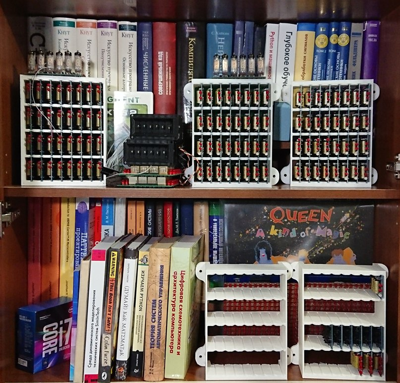
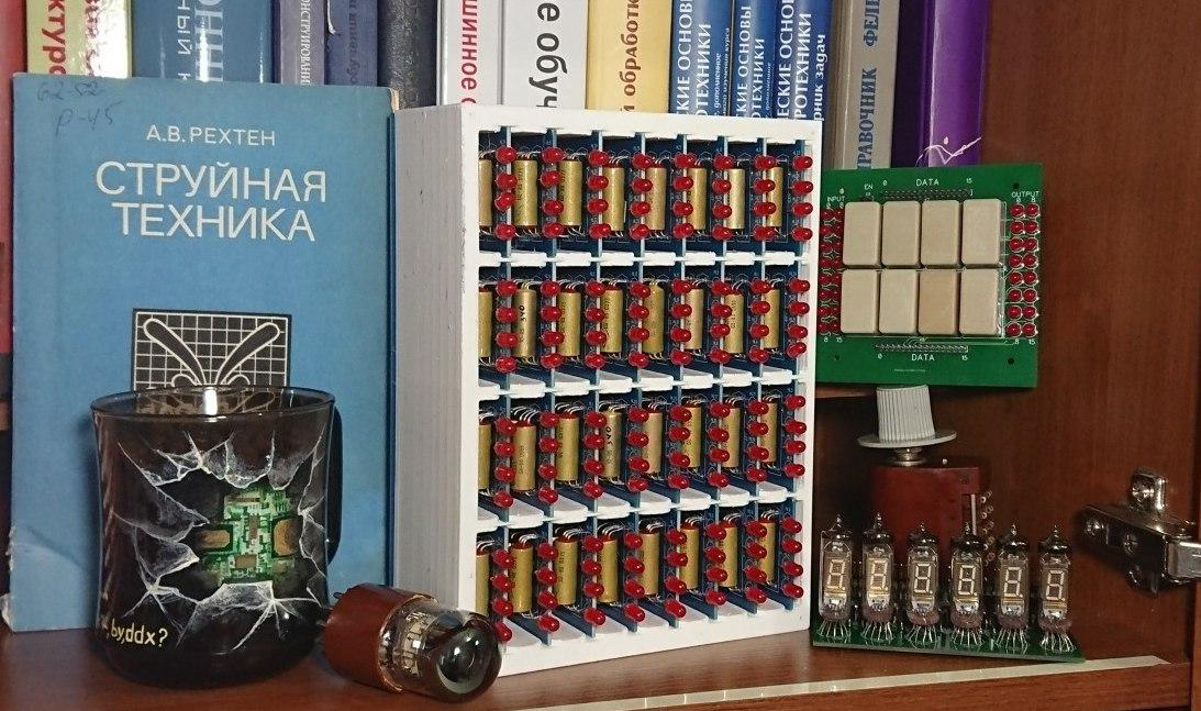
I printed all cases for blocks and need to commit first revision of logic blocks schematics. Without this step I have no idea what modules I need to solder next.
Now my bookcase looks like this :)
-
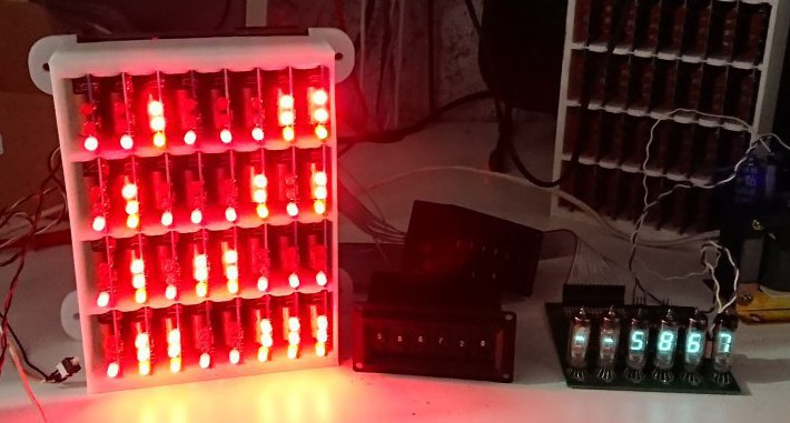
Assembled Relay Blocks working!
02/08/2018 at 12:09 • 2 commentsTwo month of assembling and 10% of BrainfuckPC done and tested!
My new video - I added Russian subs, so English subs should be generated automatically - but everything is clear, so :)
-
BfMonday#5 Adder and register blocks work!
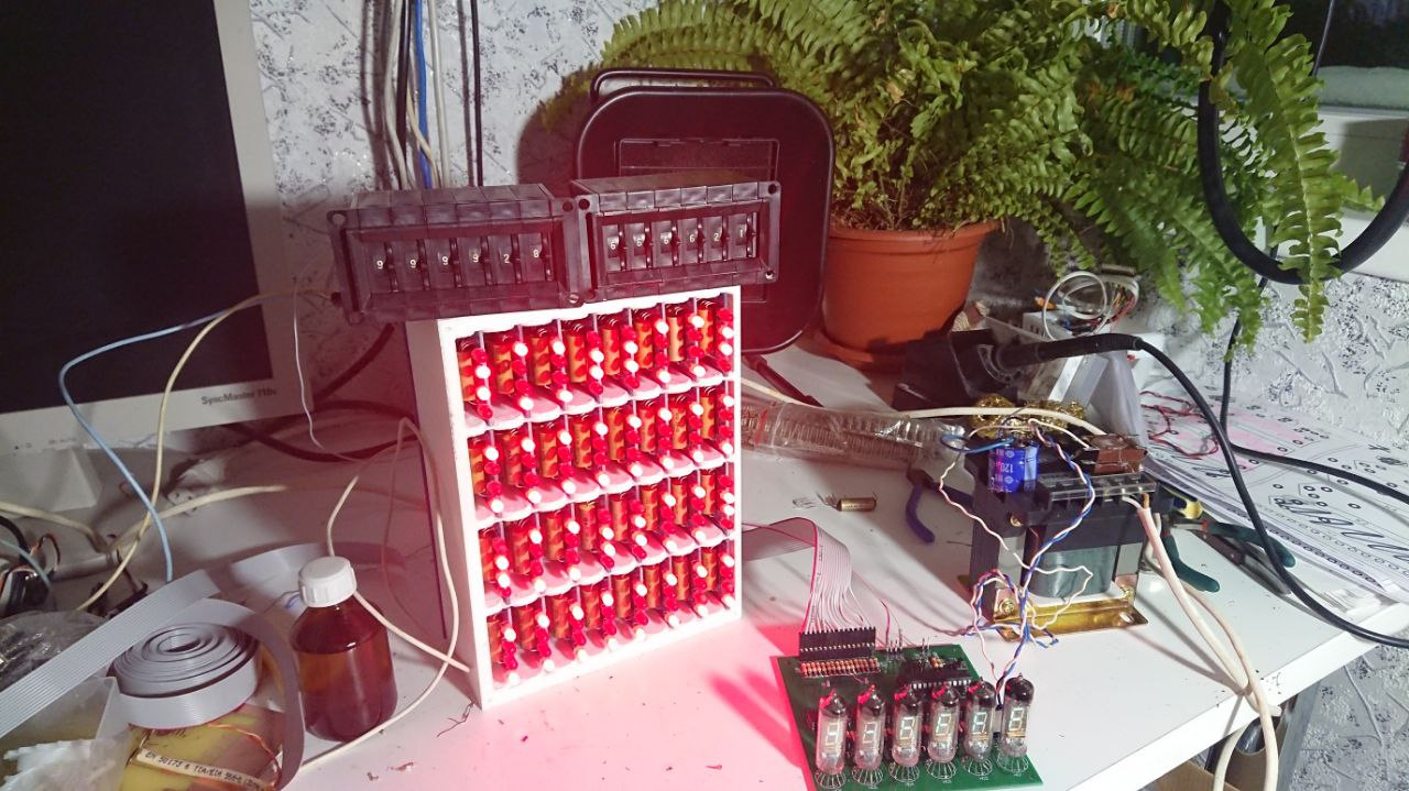
02/05/2018 at 07:28 • 0 commentsI connected assembled blocks to PSU and check them. So, they work!
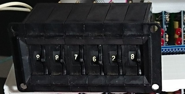
I use this switches to send data to input:
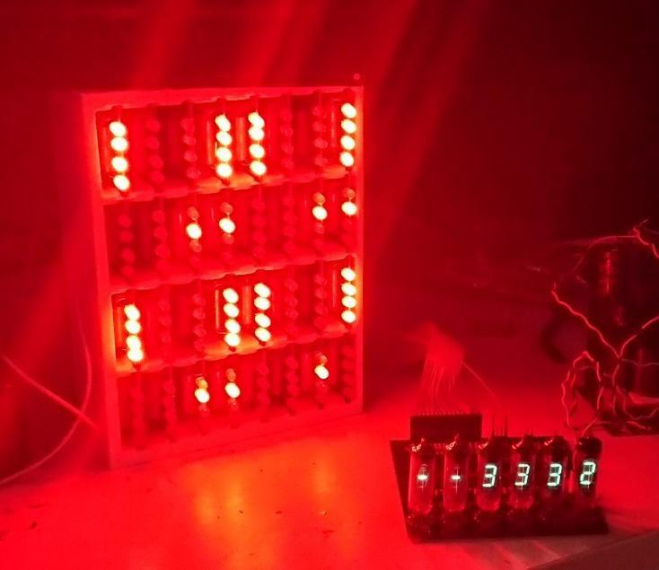
So, Adder is counting (0x9999 + 0x6666 = 0xFFFF):
And register block remember input values:
This Thursday I publish video with checking progress. I added manual Russian subs, so auto-translated English subs should be available.
Stay tuned!
-
BfMonday#4 Register block is done! (1/2)
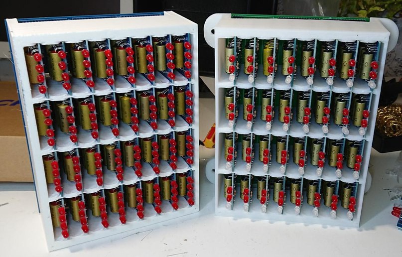
01/29/2018 at 07:47 • 4 commentsInstead of a thousand words:
![]()
One of two required registers blocks is done! 2 Independent parallel 16-bit registers(right block).
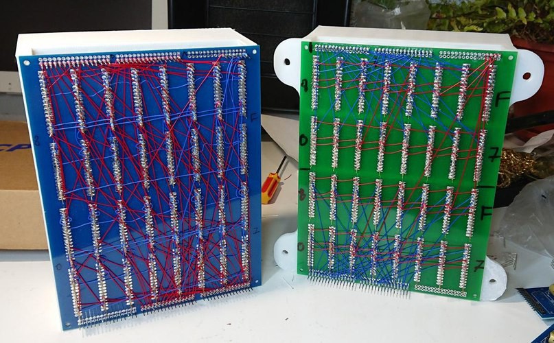
![]()
Back view. ~150 wire-wrapped jumpers, about 4 hours of work.
Some bonus for those who open project log page:
-
BfMonday#3 Registers block and indicators
01/22/2018 at 05:46 • 0 commentsContinue assembling differens staff as for checking adder or for another computer logic.
Start working on register block - two 16-bit registers. Each bit need one 1-bit register module, so I create base plate and support for them with HIPS plastic.
Another deal that I added SPI wrapper, so currently indicator board can show state from 16-bit input. (there are two 74HC165D on it)
-
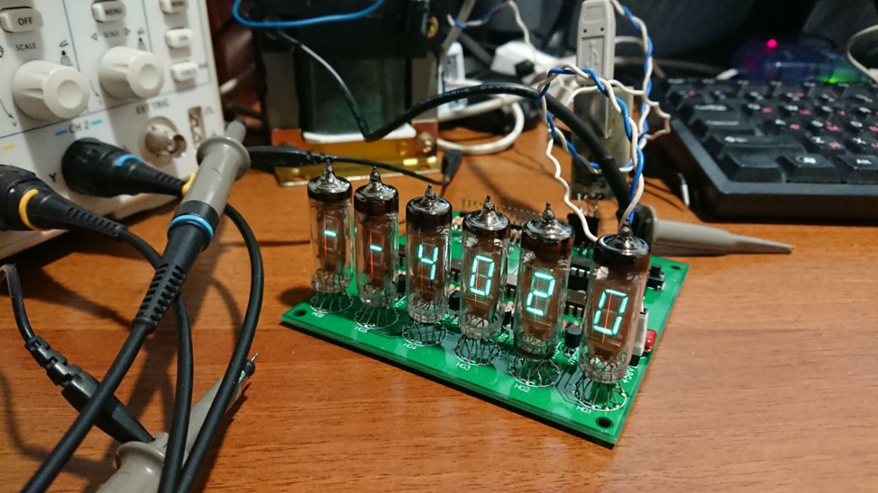
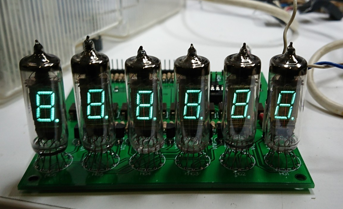
BfMonday#2 IV-6 vacuum indicators panel
01/15/2018 at 21:17 • 0 commentsIndicator panels are intended for displaying various information. Whether the current value of the register (16-bit input exactly for this), or something else received by UART. Anyway, you can always make a clock :). Why are the 6 not 8? Just because 100x100mm PCB very cheap.
![]()
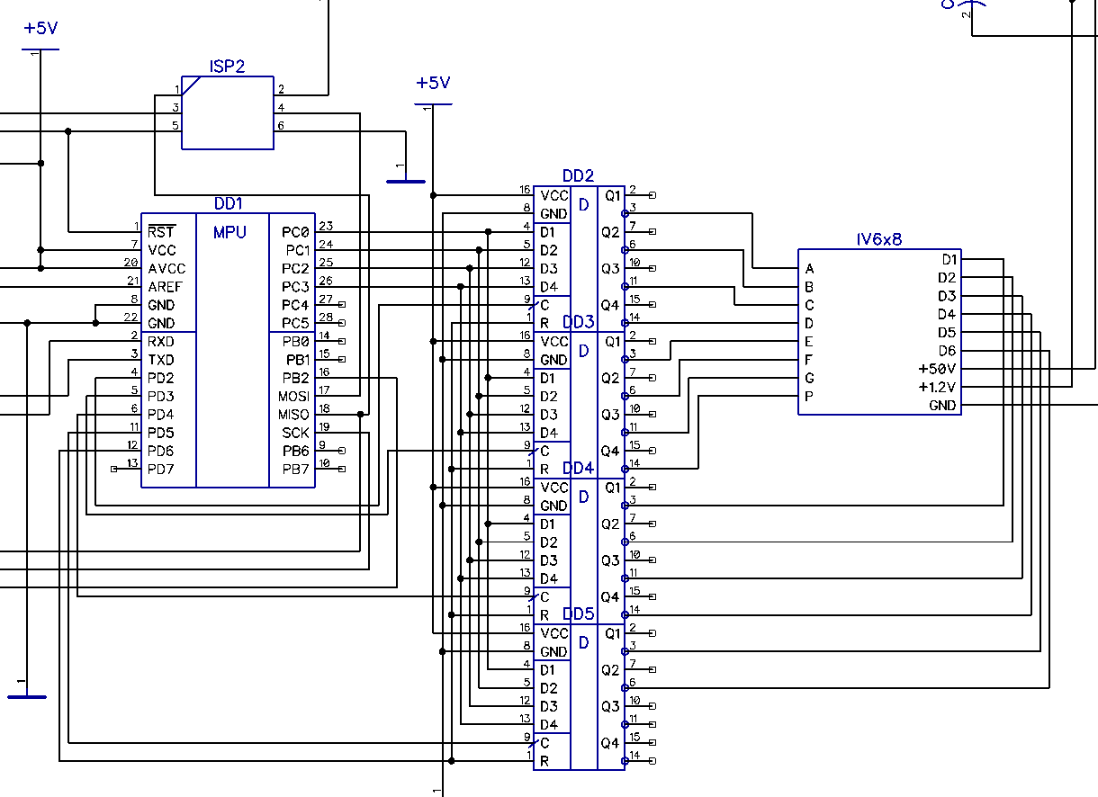
Circuitry is simple and was done on the principle "From what I found." And I found a pinch of ATMega168 controllers and two hundred cases of quad D-flip-flops K155TM8
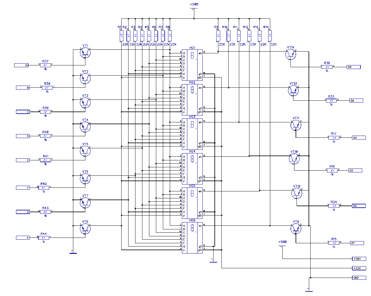
Segments in parallel, everything is polled up to power and shunted to ground by transistors. Keys, by the way - 2N2222 - at 60V.
It's clear that besides the board itself, you need a firmware too, so we uncover AVR ISP mkII, Atmel Studio and remember what it is - debug the programs having only some digital outputs available.
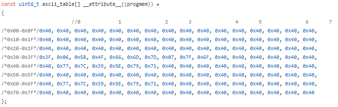
The firmware is here: https://github.com/radiolok/brainfuckpc/tree/master/fw
The ASCII table is clogged with dashes. Only HEX-numbers have been added so far. Does anyone have a more complete table? To be honest, I have not looked for it yet, but I'm too lazy to fill in the letters myself. Formatting tabs, yeah, where without it ...
Happiness? No. After sending ABCDEF I got EBFACD.
Crap - digits are not in order to simplify wiring. Dirty hack in the form of an array of six elements solves the problem. So what? The code will all endure.
Working!
The refresh rate is 500Hz, this is more than enough to not see the flicker alive.
Next tasks: add a UART-ring for messaging, find a bootloader for 8MHz, connect a 16-bit input.
-
WW2.5: IV-6 Indicator panel fw development
01/12/2018 at 08:58 • 0 commentsWorking onIV-6 indicator panel MCU firmware. Main functions are:
Read from 16-bit input current value (from register) and print it in HEX view with prexif (e.t. IP, AP, CP) or without
OR
Read from UART some string (e.g. with current clockticks counter value) and show it on indicators.
Just PoweOn test:
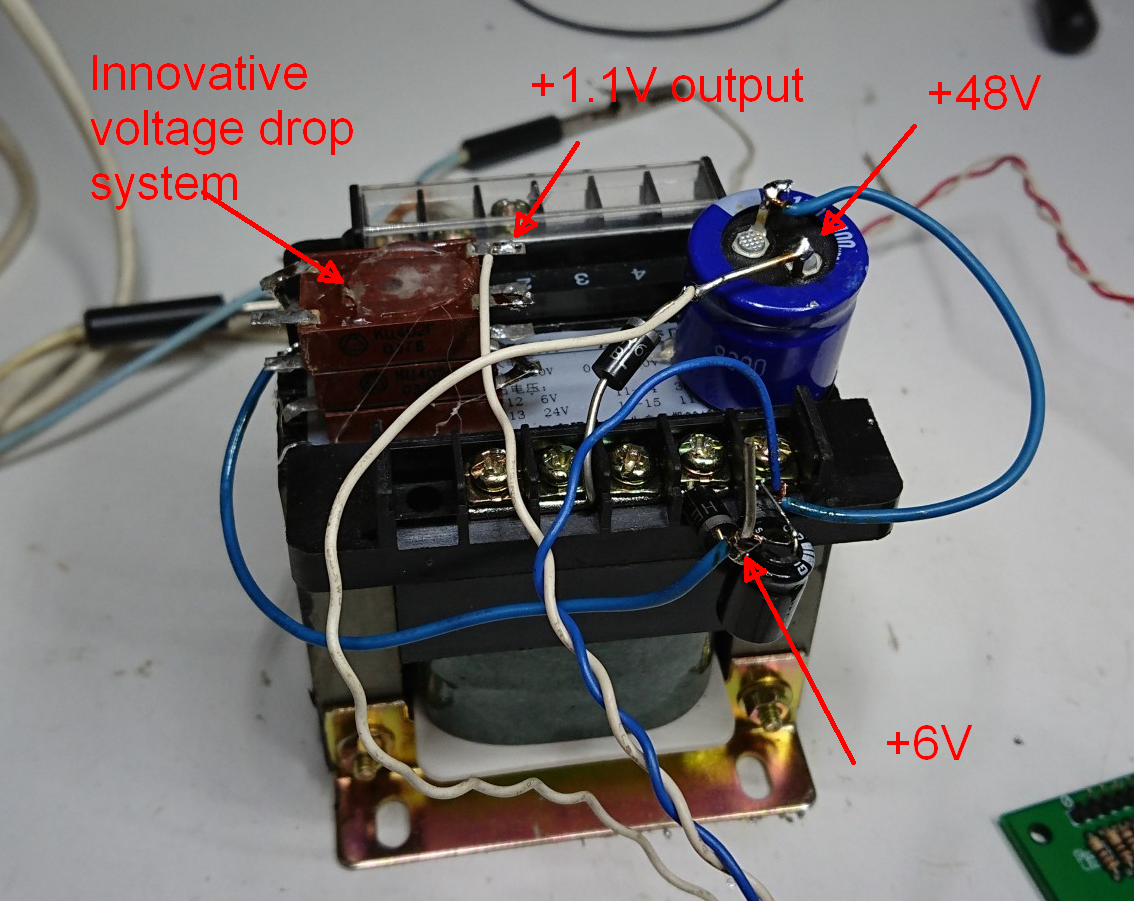
SUDDENLY I have no power supply yet for BFPC! I need to order PSU's:
5V - 200W - main relay voltage
48V - 50W - IV-6 indicators anode voltage
1.2V - 10W - IV-6 indicators heating
As I have no 48V/1.2V power supply, I have to create junk-style one:
despite the appearance it works good.
-
WW52.6 Happy new year!
12/30/2017 at 10:06 • 0 comments -
WW52.4 Adder Block Assembled
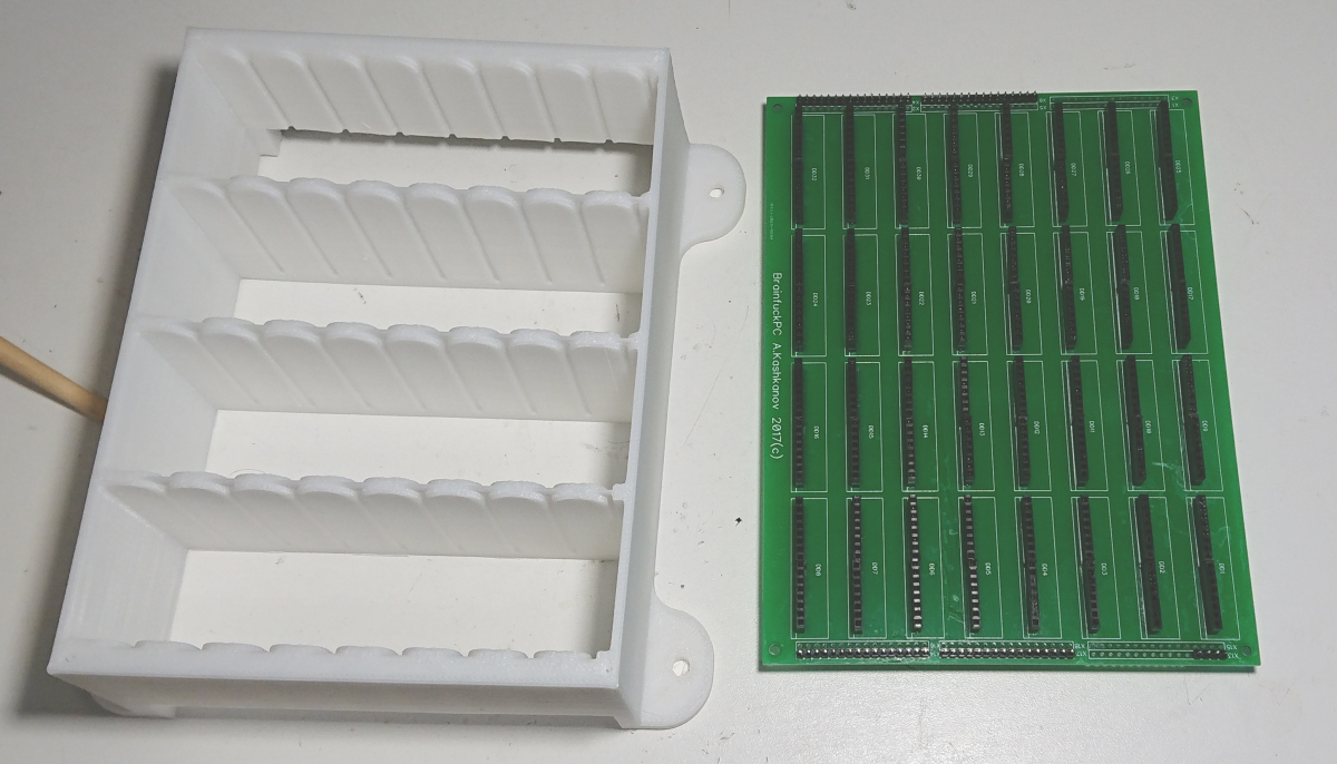
12/28/2017 at 09:27 • 1 commentPrint block-basket (as blockbaster, but only basket:) ) and install all modules inside. Each module has it's own rails.
Book on the left of the picture - A.W. Rechten - Fluidik (translation from Deutsche), about fluid logical elements.
On the right - soldered indicator board (need 10 of them) and 16-bit latch (need 10 of them too).
-
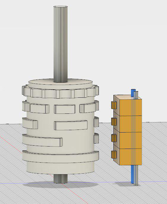
WW52.2 Test suite
12/26/2017 at 08:31 • 0 commentsI'm developing an "absolute encoder" - 16 position switch with binary output. I already have two this switches, but for one word I need 4 of them, so I want to draw all parts and print them.
On the left - key cylinder with binary rings, on the right - miniature switches. Top ring is to hold cylinder in each position. I'll add little spring-loaded balls between them - the same mechanism I found in my real switches.
BrainfuckPC Relay Computer
Von-Neumann 16-bit relay computer with Brainfuck++ instruction set