Artem Kashkanov
-
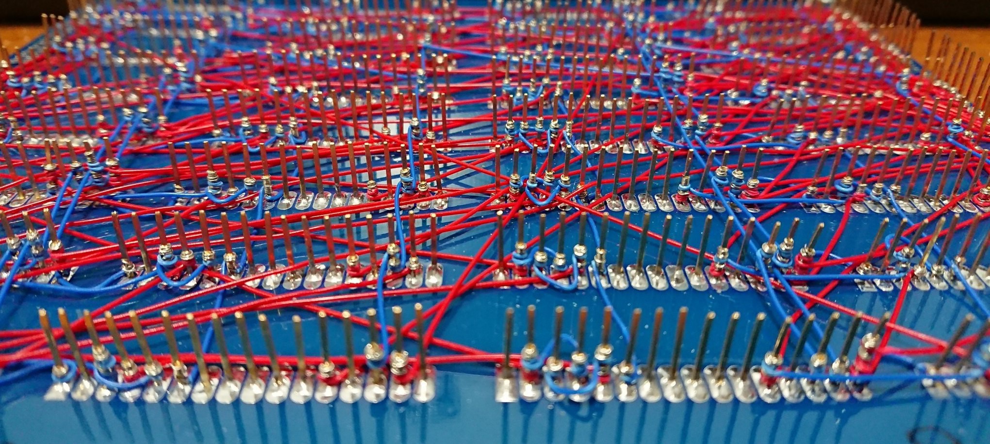
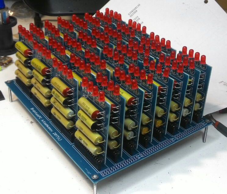
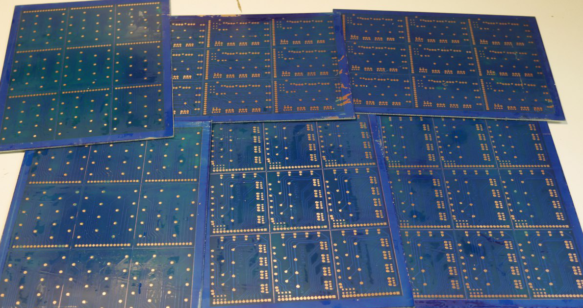
WW52.1 16 bit ADDer Wire-wrapping DONE!
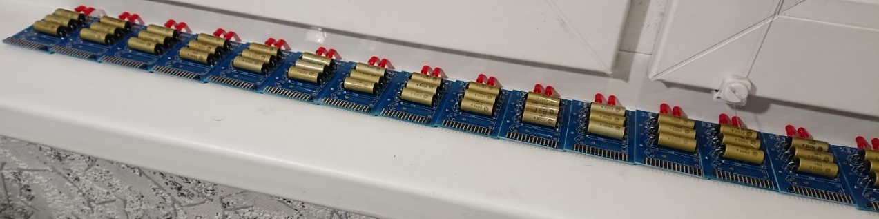
12/25/2017 at 09:03 • 4 commentsI'm done with Adder block wire-wrapping. 32 modules, 2 modules per bit. Bit Placement:
Top rows - FEDCBA98, Bottom rows - 76543210, So two bytes in natural view
![]()
Not good with wire-wrapping yet - can't place wires smoothly, but already can do isolated turns.
Next steps - need some test suite for checking blocks
-
WW51.5: 30/70 D-Triggers [DONE]&[TESTED]
12/22/2017 at 08:24 • 0 commentsDone with 30 D-triggers. I need 70 of them, so this task is not completed yet.
-
WW51: Wire-wrap is still boring. Why I bought 25 dekatrons??
12/19/2017 at 08:09 • 1 commentStill continue wire-wrapping of Adder block. Think will do this up to the end of the year.
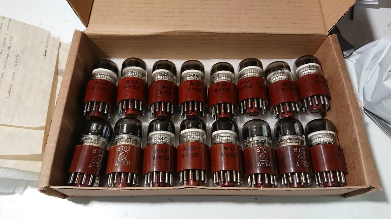
But why I bought 25 selector dekatrons?? (16pcs A101, 4pcs A102 5pcs A103)
Look how cool dekatron spinner (On A103) works on 920fps rate:
-
WW50: Wire-wrapping is too boring
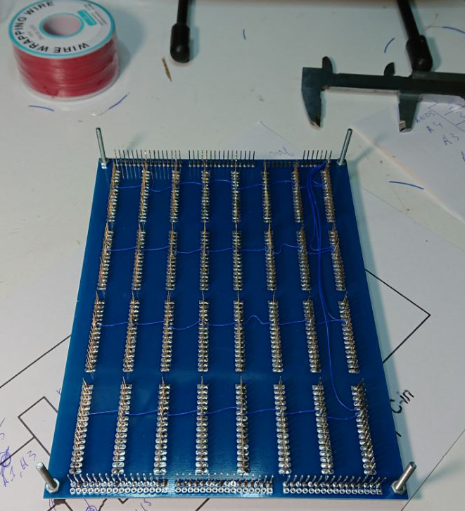
12/14/2017 at 07:23 • 0 commentsI start wire-wrapping on Adder block. Hundreds wires per block.
Just at the beginning of the process - only GND line is connected yet(already not). Thats my first steps in wire wrapping
Do not buy Blue wire if you want to use it with blue pcb! :(
Current number of modules soldered - 64 - so it's 1/3 of overall modules count.
-
WW49: D-triggers active soldering
12/08/2017 at 13:07 • 0 commentsOne more week - one more soldered parts.
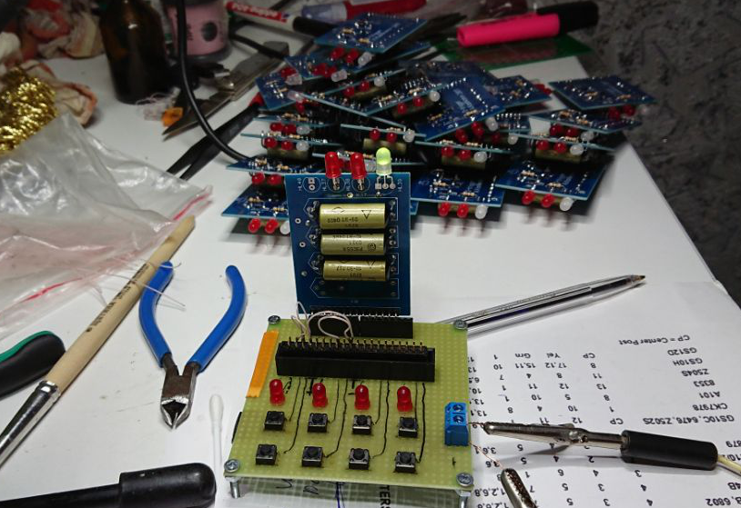
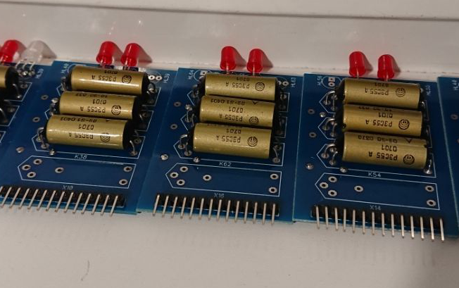
D-triggers with D and Sync input. Schematic supports En input for connecting Q to the output, but because of limited number of RES55 I have to use external 16-bit switches. Because of it this modules contain only 3 relays. Currently 17 are almost done(need to solder two-color led), need 70 of them
There only 3 LED's - Data and WR, and two-color LED shows Q/~Q output
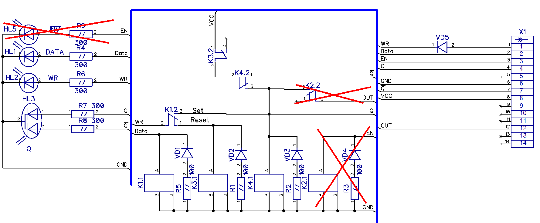
Module schematic (under red non-soldered parts)
-
WW48.1 PerfMon counters boards
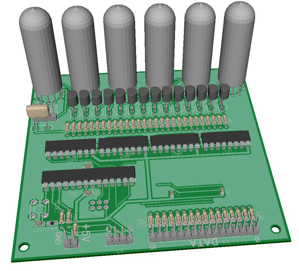
11/27/2017 at 07:38 • 0 commentsCreated and already ordered pcb's for 7-segment display on soviet indicators IV-6. I made one 100x100mm board(5$ x 10pcs on easyeda) with 6 digits, but I'll make 10 boards - 5 boards per line,
so I will have 30x2 digit display.
Would be used for showing current states of all registers - IR, AR, TR, CMD_R and for instruction retired and cycles count.
3D render is here, dynamic indication, K155TM8 4xD-triggers for anodes and cathodes, atmega168 as controller.
-
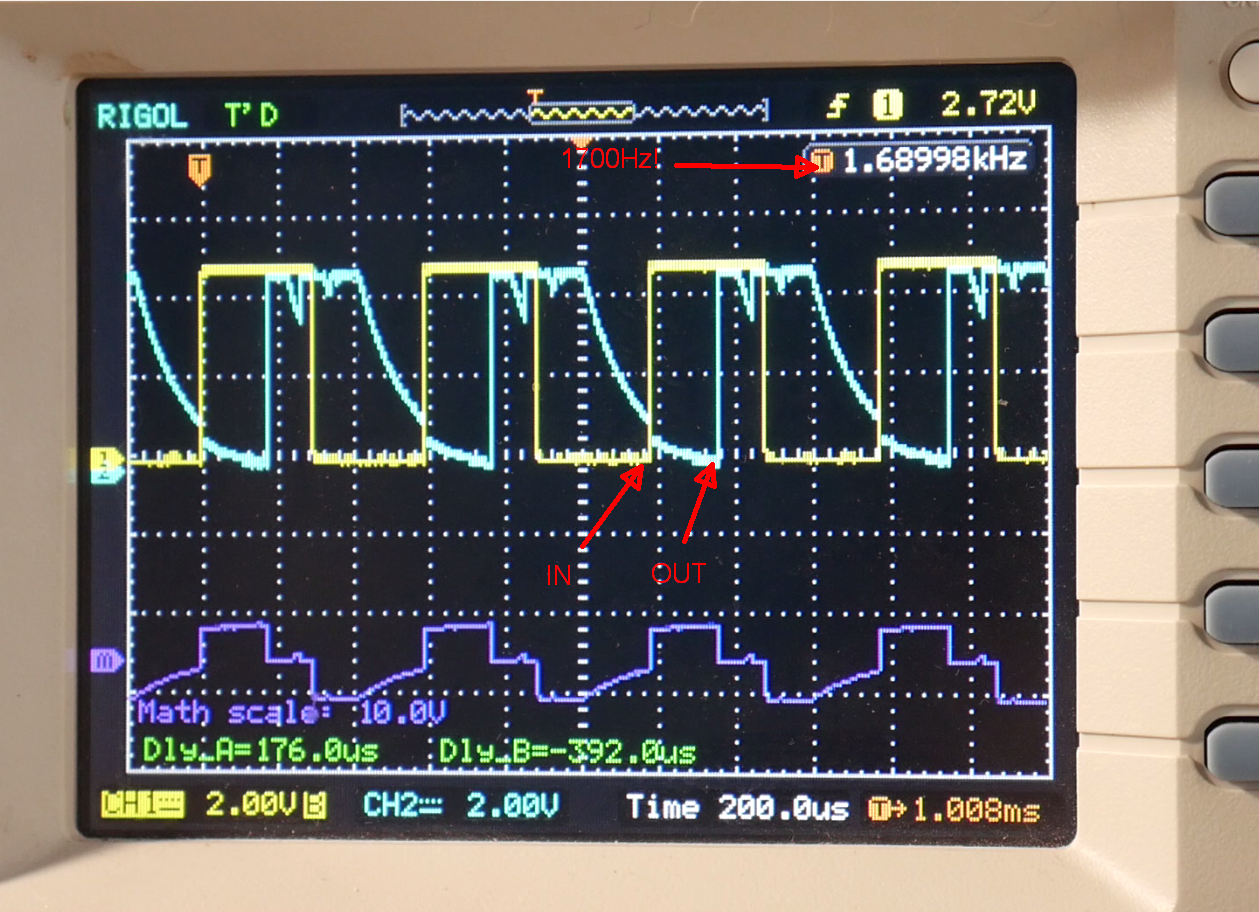
WW47.1 Update: Reed Relay Speed Test 1700Hz!
11/20/2017 at 18:31 • 0 commentsDid speed testing for relays. Results:
RES55 - 1700Hz on 50% duty cycle - 300us/600us ON/OFF delay
RES64 - 1600Hz on 50% duty cycle - 200us/400us ON/OFF delay - Why this is slower? ;-)
On 1200Hz both types of relay works very stable with clean charts, on max speed contact bounce become visible. Signal decreases to zero so slowly because of Open circuit.
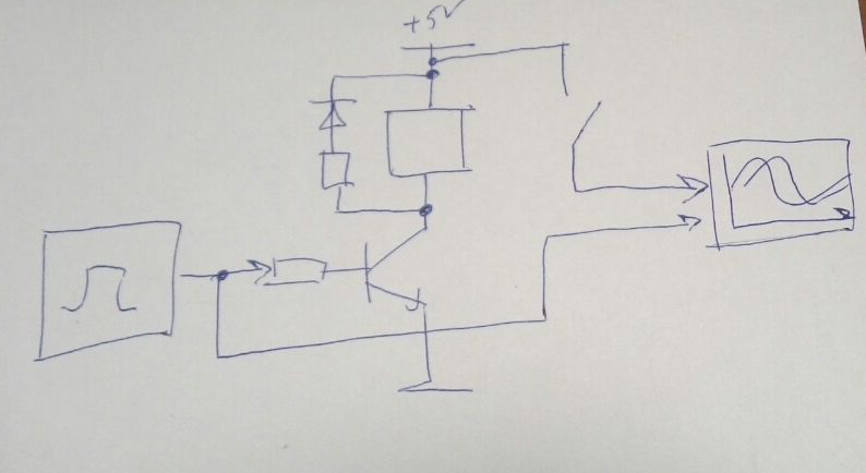
Schema is very simple:
Set square signal to transistor, and get signal from one relay output:
-
WW46 Update
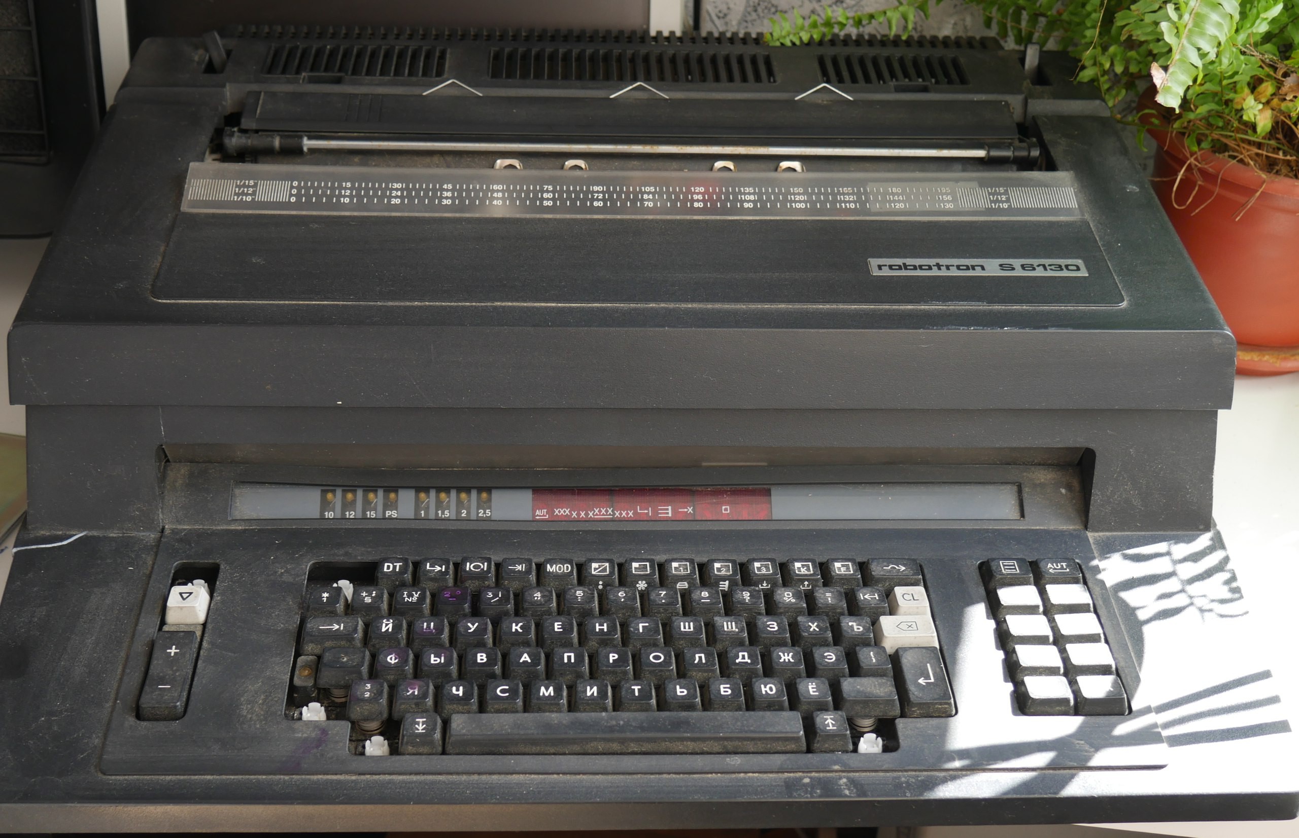
11/16/2017 at 08:19 • 1 commentHow about using this for input/output operations with my computer?
![]()
It's a electronic daisy-wheel typewriter Robotron S6130 with Terminal support - it can be connected via RS-232 to computer and print received data. It have Russian daisy-wheel and keyboard layout, but wheel can be changed to another one.
Unfortunately it doesn't work, but I have schematic and want to repair it - internals looks not bad.
Here is my review, But sorry, Currently Russian language only and no subs.
-
WW45 Update
11/12/2017 at 14:49 • 0 comments- Ordered pcbs from easyeda and got it.
- Soldered all 2AND/2XOR modules for carry-chain adder. Start soldering base plate for it.
- Done with modules tester - didn't check any relay but will check all modules.
![]()
-
WW23 Update
06/05/2017 at 06:53 • 0 commentsOh man.. Third attempt was successful and I painted six boards with solder mask. Currently I need to repeat this procedure for other 24 boards. But I already can start drill and mill boards and start assembling.
Current pallet I use for painting is not very good and I need another one to get more smooth surface.
![]()
BrainfuckPC Relay Computer
Von-Neumann 16-bit relay computer with Brainfuck++ instruction set