mulcmu
-
Rev 2 Built
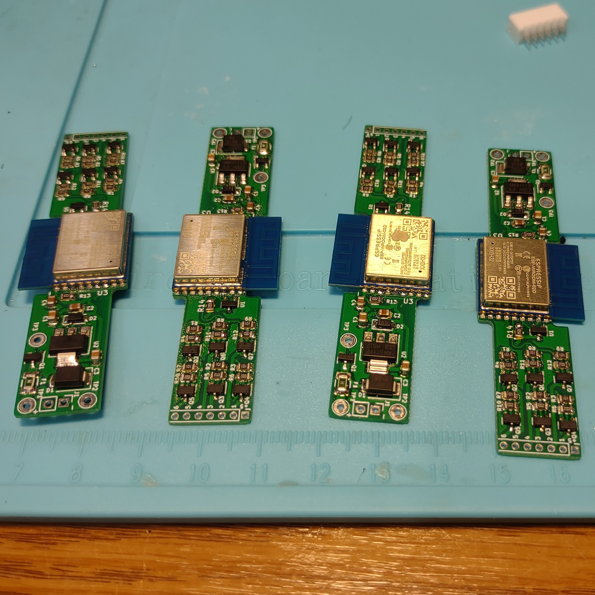
07/30/2022 at 02:08 • 0 commentsI built up 4 of the Rev 2 boards. I've been using up a 5 year old tube of solder paste by adding some fresh flux and mixing it up on the stencil before spreading. This round turned out a bit thin and spread out a bit too much on some of the pads. A bunch of tombstones and misaligned SOT-23 after reflow.
The voltage supervisors was still causing some issues. The 3.3V regulators on 2 of the boards were in the 3.25 range and that wasn't enough to satisfy the supervisor so the ESP was held in reset. I ended up removing them and boards worked fine, for future builds getting a 3.2V or 3.15V threshold supervisor.
An unpopulated Rev 1 PCB was used to make a generic bed of nails adapter for a programing fixture. It worked well enough for programming a few by hand.
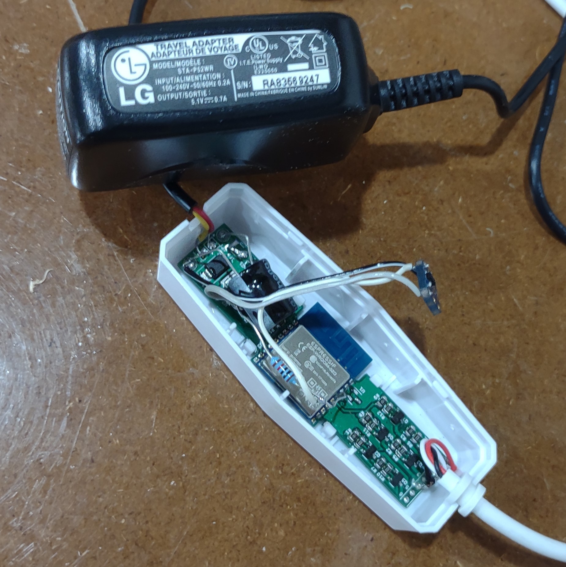
The replacement grow light was upgraded with a Rev 2 board. The PCB fit in the alternate style case with one modification to clip a plastic standoff interfering with the ESP shield. The Rev 2 boards used a 2A poly fuse and this light was built using a 2A barrel jack with corresponding pigtail to connect with the control box.
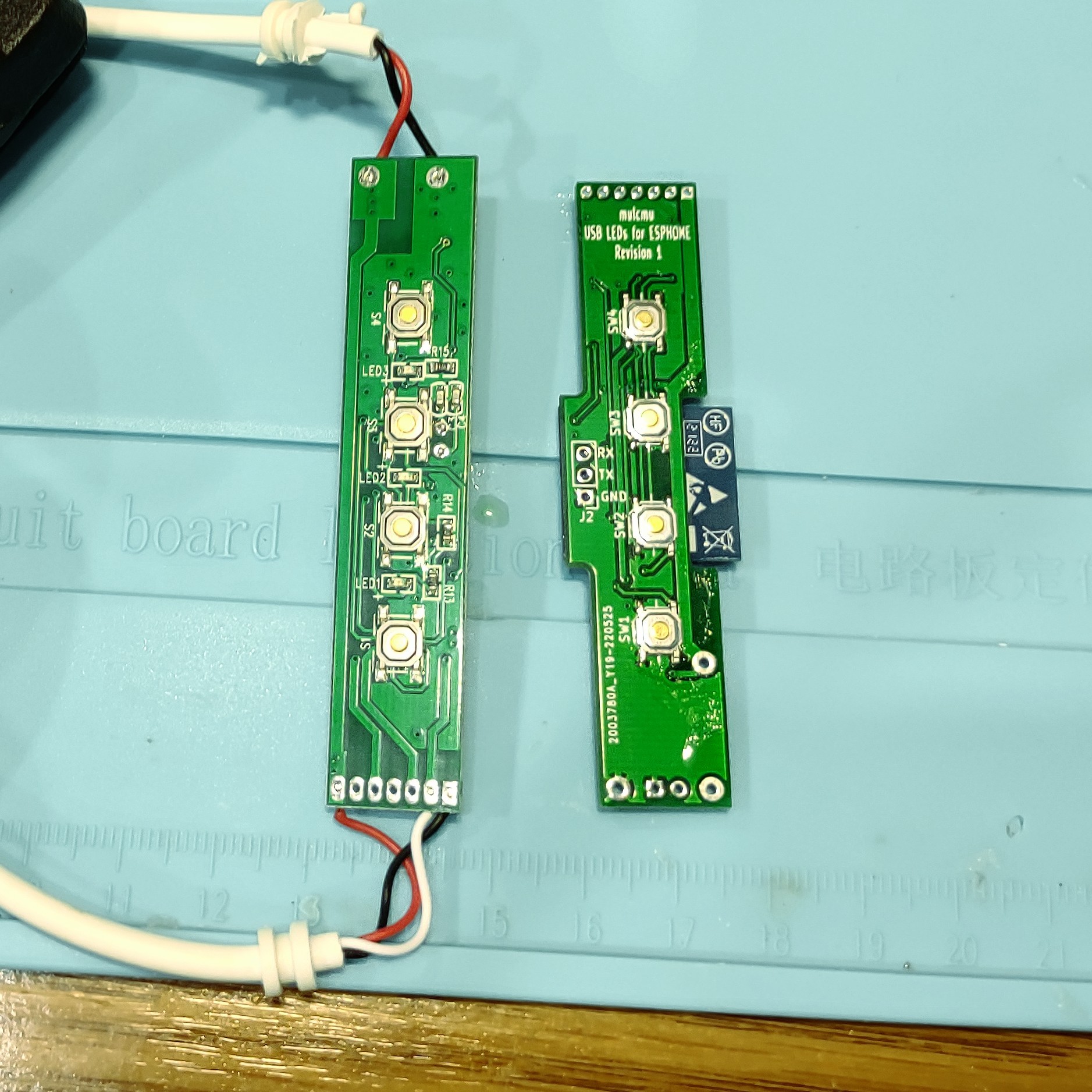
Lack of LED on the board makes troubleshooting difficult and the user feedback seems to be missing. The only unused pin is the TX line which could be utilized for some feedback, just not one that is always on and light up a dark room bright.
![]()
![]()
-
Rev 1 Testing
07/02/2022 at 01:02 • 0 commentsThe Rev 1 PCB with the voltage supervisor and pull up resistor changes from rev 2 tested fine using a small perf-board LED setup with USB power. ESPHome configuration was created and installed. The ESP8266 would connect to wifi only on the first attempt. Subsequent reboots of the ESP8266 would try to establish connection with router but would never succeed until router was rebooted. This was annoying and seems to be an issue with the DHCP configuration. Setting the ESPHome board to a static IP address seems to be an adequate work around.
The breakout board was removed and the real lights were installed. They would work for a while sporadically and then turn off. Troubleshooting identified the 500mA poly-fuse was tripping. I tested one of the light bulbs and it used 900mA at 5V. Testing the stock controller showed that the duty cycle was limited to about 15%. The poly fuse was replaced with a pin header to short the pads. Test board was connected to bench power supply and the duty cycle was adjusted to get current draw of about 700mA between both lights. An old 5V 700mA phone charger was cannibalized to finish the assembly for more software development.
Test software posted on github.
![]()
-
Rev 2 PCB
06/28/2022 at 20:52 • 0 commentsRev 2 of the PCB fixes reset issue.
Posted in Github repository.
![]()
-
Rev 1 PCB
06/24/2022 at 14:44 • 0 commentsRevision 1 PCB was designed to fit inside the existing control enclosure for the lights. The ESP-WROOM would fit in the enclosure but needed some offset cuts in the PCB. A similar set of lights had the same controls but the plastic molding was different to retain the board in place. The PCB should fit either of these two style cases.
Ordered 5 prototype PCB from jlcpcb and stencil from oshstencil. The assembly went okay despite the solder paste going on a bit messy.
Initial testing went okay. The board kept resetting due to lack of pull-up on the reset line. The voltage supervisor was removed during the troubleshooting. Rev 2 in progress to add the pull-up resistor. Might change the supervisor to 3.3V too.
Arduino test code loaded on okay to test the lights and buttons. Took a good bit of searching to find the INPUT_PULLDOWN_16 to enable the pulldown on GPIO16.
Next step to get rev 2 PCB on order and start working on ESPHome configuration to properly IOT it into home assistant.
![]()
IOT the USB Grow Lights
Fix broken 5v grow lights and IOT them in the process.