Guillermo Perez Guillen
-
6. Test and Conclusion
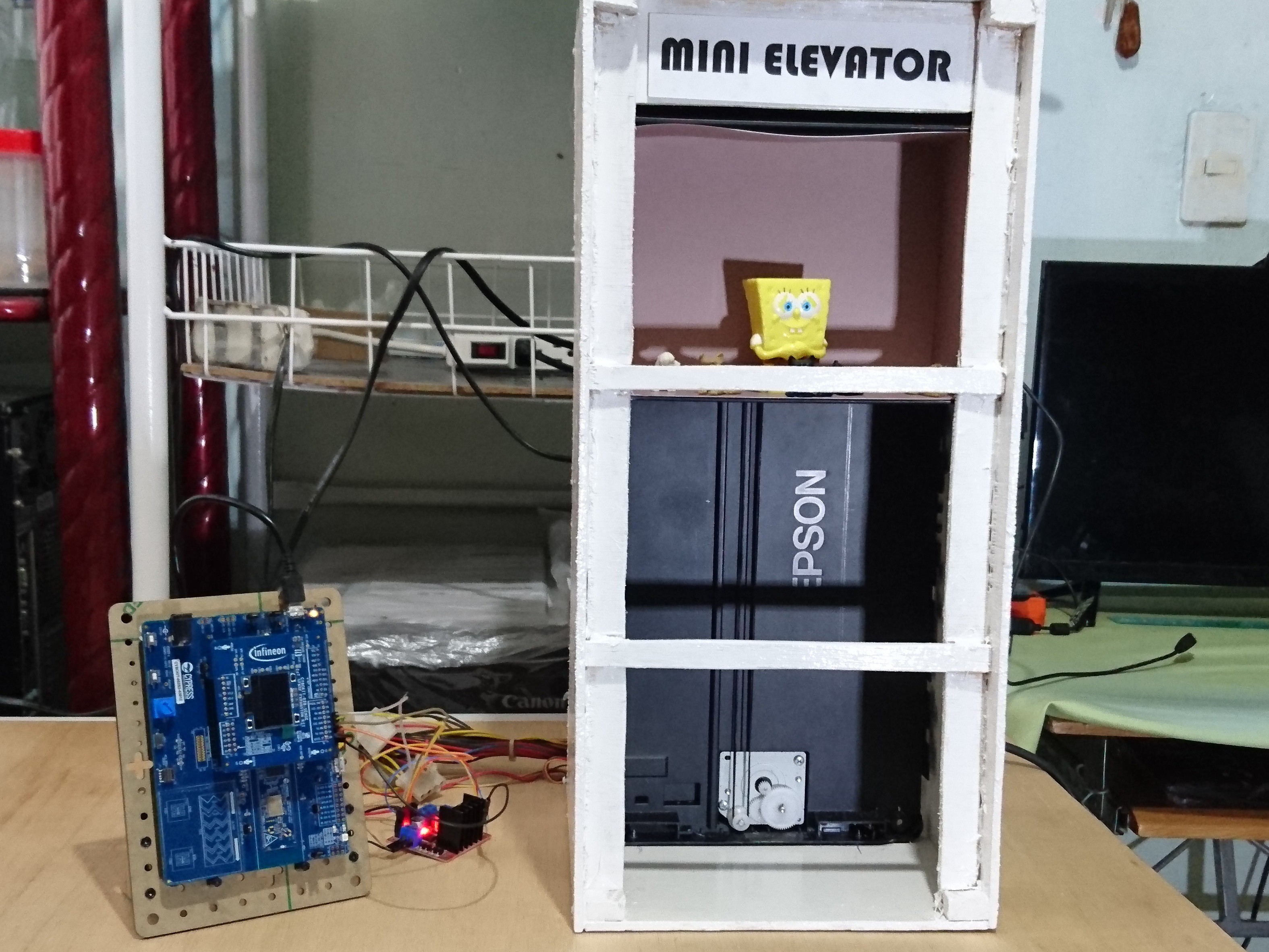
06/27/2022 at 20:48 • 0 commentsBelow I show you the video of the test done with the mini elevator.
Conclusion:
- I have achieved my goal of building a mini elevator with my PSoC 62S2 Wi-Fi BT Pioneer Kit, and IoT sense expansion kit;
- I have also incorporated the Picovoice platform into my project to experiment and create wake words;
- I still have plans in the future to make more changes to this project, such as try with another techology, or maybe adding a small sliding door, or a display that tells me the floor number, or even adding environmental sensors.
-
5. Picovoice Platform
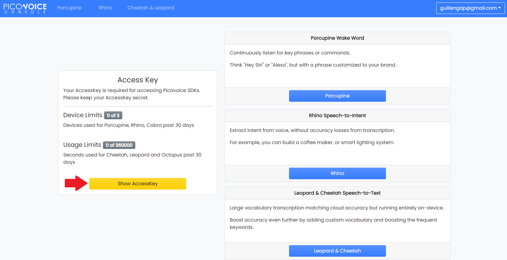
06/27/2022 at 20:45 • 0 commentsPicovoice is the end-to-end platform for building voice products on your terms. Unlike Alexa and Google services, Picovoice runs entirely on-device while being more accurate. Using Picovoice, one can infer a user's intent from a naturally spoken utterance such as: Hey Edison, set the lights in the living room to blue.
![]()
For my purposes, it is enough to use the free account. so following the webinar instructions I got the access key right away.
![]()
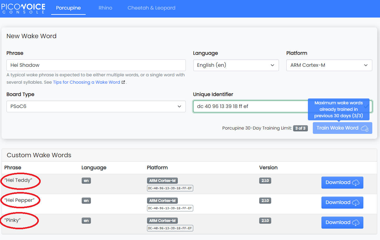
I have created three wake words of which I have used one of them in my project.
![]()
-
4. ModusToolbox Software
06/27/2022 at 20:41 • 0 commentsI downloaded and install the software ModusToolbox 2.4 in its version for Windows
![]()
I recommend you follow the instructions in this webinar, since some steps will serve as a reference: Implementing Machine Learning on the Edge
To develop my project, I will use the next code demo as a reference: "Picovoice_Porcupine_Wake_Word_Demo".
Step 1. Click on: File> New> ModusToolBox Application
![]()
Step 2. Insert kit name: CY8CKIT-062S2-43012, and click next
![]()
Step 3. Select "Picovoice_Porcupine_Wake_Word_Demo" poject, and click on create. Below is the project:
![]()
Step 4. Open main.c file and make the next changes:
// AUTHOR: GUILLERMO PEREZ GUILLEN

#include <stdbool.h>
#include <stdio.h>
#include <stdlib.h>

#include "cy_rgb_led.h"
#include "cybsp.h"

#include "pv_audio_rec.h"
#include "pv_keywords.h"
#include "pv_porcupine.h"
#include "pv_psoc6.h"

#include "cy_pdl.h"
#include "cyhal.h"
#include "cy_retarget_io.h"

#define MEMORY_BUFFER_SIZE (70 * 1024)

static const char* ACCESS_KEY = "gkylTu/7ljkHnB1/yobm78094/ea8DZ59MN7xcgWduJU1278u6AyGg=="; // AccessKey string obtained from Picovoice Console (https://picovoice.ai/console/)

static int8_t memory_buffer[MEMORY_BUFFER_SIZE] __attribute__((aligned(16)));

#define DELAY_LONG_MS           (2)   /* ADD 2 milliseconds */

#ifdef __PV_LANGUAGE_ENGLISH__

static const int32_t NUM_KEYWORDS = 4;
static const int32_t KEYWORD_MODEL_SIZES[] = {
        sizeof(DEFAULT_KEYWORD_ARRAY),
        sizeof(PINKY_KEYWORD_ARRAY),
        sizeof(BUMBLEBEE_KEYWORD_ARRAY),
        sizeof(ALEXA_KEYWORD_ARRAY)
};
static const void *KEYWORD_MODELS[] = {
        DEFAULT_KEYWORD_ARRAY,
        PINKY_KEYWORD_ARRAY,
        BUMBLEBEE_KEYWORD_ARRAY,
        ALEXA_KEYWORD_ARRAY
};
static const float SENSITIVITIES[] = {
        0.75f,
        0.75f,
        0.75f,
        0.75f
};

static const char *KEYWORDS_NAME[] = {
        "Porcupine",
        "Pinky",
        "Bumblebee",
        "Alexa"
};

#else

static const int32_t NUM_KEYWORDS = 1;
static const int32_t KEYWORD_MODEL_SIZES[] = { sizeof(DEFAULT_KEYWORD_ARRAY) };
static const void *KEYWORD_MODELS[] = { DEFAULT_KEYWORD_ARRAY };
static const float SENSITIVITIES[] = { 0.75f };
static const char *KEYWORDS_NAME[] = { "" };

#endif

static void error_handler(void) {
    cy_rgb_led_on(CY_RGB_LED_COLOR_RED, CY_RGB_LED_MAX_BRIGHTNESS);
    while(true);
}

int main(void) {

    uint32_t delay_led_blink = DELAY_LONG_MS;
    cy_rslt_t result;

	result = cyhal_gpio_init(P0_2, CYHAL_GPIO_DIR_OUTPUT, CYHAL_GPIO_DRIVE_STRONG, CYBSP_LED_STATE_ON);
    result = cyhal_gpio_init(P0_3, CYHAL_GPIO_DIR_OUTPUT, CYHAL_GPIO_DRIVE_STRONG, CYBSP_LED_STATE_ON);
    result = cyhal_gpio_init(P1_3, CYHAL_GPIO_DIR_OUTPUT, CYHAL_GPIO_DRIVE_STRONG, CYBSP_LED_STATE_ON);
    result = cyhal_gpio_init(P13_6, CYHAL_GPIO_DIR_OUTPUT, CYHAL_GPIO_DRIVE_STRONG, CYBSP_LED_STATE_ON);

    if (result != CY_RSLT_SUCCESS)
    {
        CY_ASSERT(0);
    }

    pv_status_t status = pv_board_init();
    if (status != PV_STATUS_SUCCESS) {
        error_handler();
    }

    status = pv_message_init();
    if (status != PV_STATUS_SUCCESS) {
        error_handler();
    }

    const uint8_t *board_uuid = pv_get_uuid();
    printf("UUID: ");
    for (uint32_t i = 0; i < pv_get_uuid_size(); i++) {
        printf(" %.2x", board_uuid[i]);
    }
    printf("\r\n");

    status = pv_audio_rec_init();
    if (status != PV_STATUS_SUCCESS) {
        printf("Audio init failed with '%s'\r\n", pv_status_to_string(status));
        error_handler();
    }

    status = pv_audio_rec_start();
    if (status != PV_STATUS_SUCCESS) {
        printf("Recording audio failed with '%s'\r\n", pv_status_to_string(status));
        error_handler();
    }

    pv_porcupine_t *handle = NULL;

    status = pv_porcupine_init(
            ACCESS_KEY,
            MEMORY_BUFFER_SIZE,
            memory_buffer,
            NUM_KEYWORDS,
            KEYWORD_MODEL_SIZES,
            KEYWORD_MODELS,
            SENSITIVITIES,
            &handle);

    if (status != PV_STATUS_SUCCESS) {
        printf("Porcupine init failed with '%s'\r\n", pv_status_to_string(status));
        error_handler();
    }

    while (true) {
        const int16_t *buffer = pv_audio_rec_get_new_buffer();
        if (buffer) {
            int32_t keyword_index = -1;
            const pv_status_t status = pv_porcupine_process(handle, buffer, &keyword_index);
            if (status != PV_STATUS_SUCCESS) {
                printf("Porcupine process failed with '%s'\r\n", pv_status_to_string(status));
                error_handler();
            }
            if (keyword_index >= 0) {
                printf("[wake word] %s\r\n", KEYWORDS_NAME[keyword_index]);

                switch (keyword_index) {
                    case 0:			// 1 -> 2 or 2 -> 3
                        cy_rgb_led_on(CY_RGB_LED_COLOR_GREEN, CY_RGB_LED_MAX_BRIGHTNESS);
                        for (int i = 1; i <= 800; i++){
    	                    cyhal_gpio_write(P0_2, CYBSP_LED_STATE_ON);
    	                    cyhal_gpio_write(P0_3, CYBSP_LED_STATE_OFF);
    	                    cyhal_gpio_write(P1_3, CYBSP_LED_STATE_ON);
    	                    cyhal_gpio_write(P13_6, CYBSP_LED_STATE_OFF);
    	                    cyhal_system_delay_ms(delay_led_blink);

    	                    cyhal_gpio_write(P0_2, CYBSP_LED_STATE_ON);
    	                    cyhal_gpio_write(P0_3, CYBSP_LED_STATE_OFF);
    	                    cyhal_gpio_write(P1_3, CYBSP_LED_STATE_OFF);
    	                    cyhal_gpio_write(P13_6, CYBSP_LED_STATE_ON);
    	                    cyhal_system_delay_ms(delay_led_blink);

    	                    cyhal_gpio_write(P0_2, CYBSP_LED_STATE_OFF);
    	                    cyhal_gpio_write(P0_3, CYBSP_LED_STATE_ON);
    	                    cyhal_gpio_write(P1_3, CYBSP_LED_STATE_OFF);
    	                    cyhal_gpio_write(P13_6, CYBSP_LED_STATE_ON);
    	                    cyhal_system_delay_ms(delay_led_blink);

                        	cyhal_gpio_write(P0_2, CYBSP_LED_STATE_OFF);
    	                    cyhal_gpio_write(P0_3, CYBSP_LED_STATE_ON);
    	                    cyhal_gpio_write(P1_3, CYBSP_LED_STATE_ON);
    	                    cyhal_gpio_write(P13_6, CYBSP_LED_STATE_OFF);
    	                    cyhal_system_delay_ms(delay_led_blink);
                        }
                        break;
                    case 1:			// 2 -> 1 or 3 -> 2
                        cy_rgb_led_on(CY_RGB_LED_COLOR_CYAN, CY_RGB_LED_MAX_BRIGHTNESS);
                        for (int i = 1; i <= 800; i++){
                        	cyhal_gpio_write(P0_2, CYBSP_LED_STATE_OFF);
    	                    cyhal_gpio_write(P0_3, CYBSP_LED_STATE_ON);
    	                    cyhal_gpio_write(P1_3, CYBSP_LED_STATE_ON);
    	                    cyhal_gpio_write(P13_6, CYBSP_LED_STATE_OFF);
    	                    cyhal_system_delay_ms(delay_led_blink);

    	                    cyhal_gpio_write(P0_2, CYBSP_LED_STATE_OFF);
    	                    cyhal_gpio_write(P0_3, CYBSP_LED_STATE_ON);
    	                    cyhal_gpio_write(P1_3, CYBSP_LED_STATE_OFF);
    	                    cyhal_gpio_write(P13_6, CYBSP_LED_STATE_ON);
    	                    cyhal_system_delay_ms(delay_led_blink);

    	                    cyhal_gpio_write(P0_2, CYBSP_LED_STATE_ON);
    	                    cyhal_gpio_write(P0_3, CYBSP_LED_STATE_OFF);
    	                    cyhal_gpio_write(P1_3, CYBSP_LED_STATE_OFF);
    	                    cyhal_gpio_write(P13_6, CYBSP_LED_STATE_ON);
    	                    cyhal_system_delay_ms(delay_led_blink);

    	                    cyhal_gpio_write(P0_2, CYBSP_LED_STATE_ON);
    	                    cyhal_gpio_write(P0_3, CYBSP_LED_STATE_OFF);
    	                    cyhal_gpio_write(P1_3, CYBSP_LED_STATE_ON);
    	                    cyhal_gpio_write(P13_6, CYBSP_LED_STATE_OFF);
    	                    cyhal_system_delay_ms(delay_led_blink);
                        }
                        break;
                    case 2:			// 1 -> 3
                        cy_rgb_led_on(CY_RGB_LED_COLOR_RED, CY_RGB_LED_MAX_BRIGHTNESS);
                        for (int i = 1; i <= 1600; i++){
    	                    cyhal_gpio_write(P0_2, CYBSP_LED_STATE_ON);
    	                    cyhal_gpio_write(P0_3, CYBSP_LED_STATE_OFF);
    	                    cyhal_gpio_write(P1_3, CYBSP_LED_STATE_ON);
    	                    cyhal_gpio_write(P13_6, CYBSP_LED_STATE_OFF);
    	                    cyhal_system_delay_ms(delay_led_blink);

    	                    cyhal_gpio_write(P0_2, CYBSP_LED_STATE_ON);
    	                    cyhal_gpio_write(P0_3, CYBSP_LED_STATE_OFF);
    	                    cyhal_gpio_write(P1_3, CYBSP_LED_STATE_OFF);
    	                    cyhal_gpio_write(P13_6, CYBSP_LED_STATE_ON);
    	                    cyhal_system_delay_ms(delay_led_blink);

    	                    cyhal_gpio_write(P0_2, CYBSP_LED_STATE_OFF);
    	                    cyhal_gpio_write(P0_3, CYBSP_LED_STATE_ON);
    	                    cyhal_gpio_write(P1_3, CYBSP_LED_STATE_OFF);
    	                    cyhal_gpio_write(P13_6, CYBSP_LED_STATE_ON);
    	                    cyhal_system_delay_ms(delay_led_blink);

                        	cyhal_gpio_write(P0_2, CYBSP_LED_STATE_OFF);
    	                    cyhal_gpio_write(P0_3, CYBSP_LED_STATE_ON);
    	                    cyhal_gpio_write(P1_3, CYBSP_LED_STATE_ON);
    	                    cyhal_gpio_write(P13_6, CYBSP_LED_STATE_OFF);
    	                    cyhal_system_delay_ms(delay_led_blink);
                        }
                        break;
                    case 3:			// 3 -> 1
                        cy_rgb_led_on(CY_RGB_LED_COLOR_BLUE, CY_RGB_LED_MAX_BRIGHTNESS);
                        for (int i = 1; i <= 1600; i++){
                        	cyhal_gpio_write(P0_2, CYBSP_LED_STATE_OFF);
    	                    cyhal_gpio_write(P0_3, CYBSP_LED_STATE_ON);
    	                    cyhal_gpio_write(P1_3, CYBSP_LED_STATE_ON);
    	                    cyhal_gpio_write(P13_6, CYBSP_LED_STATE_OFF);
    	                    cyhal_system_delay_ms(delay_led_blink);

    	                    cyhal_gpio_write(P0_2, CYBSP_LED_STATE_OFF);
    	                    cyhal_gpio_write(P0_3, CYBSP_LED_STATE_ON);
    	                    cyhal_gpio_write(P1_3, CYBSP_LED_STATE_OFF);
    	                    cyhal_gpio_write(P13_6, CYBSP_LED_STATE_ON);
    	                    cyhal_system_delay_ms(delay_led_blink);

    	                    cyhal_gpio_write(P0_2, CYBSP_LED_STATE_ON);
    	                    cyhal_gpio_write(P0_3, CYBSP_LED_STATE_OFF);
    	                    cyhal_gpio_write(P1_3, CYBSP_LED_STATE_OFF);
    	                    cyhal_gpio_write(P13_6, CYBSP_LED_STATE_ON);
    	                    cyhal_system_delay_ms(delay_led_blink);

    	                    cyhal_gpio_write(P0_2, CYBSP_LED_STATE_ON);
    	                    cyhal_gpio_write(P0_3, CYBSP_LED_STATE_OFF);
    	                    cyhal_gpio_write(P1_3, CYBSP_LED_STATE_ON);
    	                    cyhal_gpio_write(P13_6, CYBSP_LED_STATE_OFF);
    	                    cyhal_system_delay_ms(delay_led_blink);
                        }
                        break;
                    default:
                        break;
                }
                Cy_SysLib_Delay(500);
                cy_rgb_led_off();
            }
        }

    }
    pv_board_deinit();
    pv_audio_rec_deinit();
    pv_porcupine_delete(handle);
}
Analysis:
- To avoid duplication of any pin used by the "IoT sense expansion kit" board, I have enabled the next four pins to take control of the stepper motor:
result = cyhal_gpio_init(P0_2, CYHAL_GPIO_DIR_OUTPUT, CYHAL_GPIO_DRIVE_STRONG, CYBSP_LED_STATE_ON);
result = cyhal_gpio_init(P0_3, CYHAL_GPIO_DIR_OUTPUT, CYHAL_GPIO_DRIVE_STRONG, CYBSP_LED_STATE_ON);
result = cyhal_gpio_init(P1_3, CYHAL_GPIO_DIR_OUTPUT, CYHAL_GPIO_DRIVE_STRONG, CYBSP_LED_STATE_ON);
sult = cyhal_gpio_init(P13_6, CYHAL_GPIO_DIR_OUTPUT, CYHAL_GPIO_DRIVE_STRONG, CYBSP_LED_STATE_ON);
- In my case, the stepper motor I have used needs 48 steps to make a 360 degree turn. The speed of rotation is controlled by the delay, that is, 2 ms.
- insert the access key obtained from the Picovoice platform in:
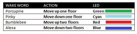
static const char* ACCESS_KEY - I have designed the wake words table shown below:
![]()
- case 0 is used to move from floor 1 to 2 or from 2 to 3;
- case 1 is used to move from floor 2 to 1 or from 3 to 2;
- case 2 is used to move from floor 1 to 3; Y
- case 3 is used to move from floor 3 to floor 1.
Step 5. I have added the "Pinky" wake word in the pv_params.h file. This wake word was obtained from the Picovoice platform as shown in the next section.
// Wake-word = pinky static const uint8_t PINKY_KEYWORD_ARRAY[] __attribute__ ((aligned (16))) = { 0xde, 0x5a, 0x0b, 0xec, 0x84, 0x04, 0xa4, 0x94, 0x5a, 0x6a, 0x1c, 0x2f, 0x62, 0xb9, 0x71, 0xc6, 0x9c, 0xf5, 0xfd, 0xe4, 0x7e, 0xfd, 0xbd, 0xc9, 0xea, 0x4b, 0x78, 0x95, 0xd4, 0xf3, 0xbe, 0x1f, 0xbe, 0x4a, 0xf9, 0x6d, 0xce, 0x10, 0x05, 0xdb, 0xbc, 0x88, 0xdf, 0x5d, 0xa4, 0xbd, 0xab, 0x4e, 0x9b, 0x9f, 0x2c, 0x17, 0x6a, 0x42, 0xb1, 0xbd, 0x21, 0x8b, 0xfe, 0x7c, 0x74, 0xbf, 0xe9, 0xb8, 0x12, 0x25, 0x28, 0x1d, 0x74, 0x4d, 0x2c, 0x48, 0x60, 0x69, 0x7b, 0x45, 0xf6, 0xc8, 0x9f, 0x42, 0x63, 0x8a, 0xe0, 0x08, 0x1d, 0xf1, 0x8a, 0xd5, 0x0c, 0x68, 0xf0, 0x19, 0x8f, 0xd0, 0x61, 0x87, 0xd4, 0x76, 0x72, 0x67, 0xf8, 0x37, 0x04, 0x38, 0xf2, 0xcd, 0x4a, 0x70, 0xc3, 0xcc, 0x7f, 0xc4, 0x97, 0x20, 0xf8, 0x53, 0x25, 0xa7, 0xc2, 0xf7, 0xfa, 0x3c, 0x47, 0xc2, 0x0a, 0x06, 0x8a, 0xc2, 0xb0, 0xf8, 0x05, 0xd3, 0x8e, 0x6d, 0x2a, 0x65, 0x5f, 0xd8, 0xfd, 0xa9, 0xcf, 0xe5, 0xd4, 0x33, 0x8e, 0xfc, 0x44, 0x72, 0x0f, 0x49, 0x3b, 0xad, 0x50, 0x5d, 0xab, 0x69, 0x17, 0xb1, 0xc3, 0x28, 0x28, 0x5a, 0x6f, 0xd8, 0xef, 0x25, 0xab, 0xe8, 0x2c, 0x30, 0x0e, 0x1b, 0xfa, 0x4a, 0x3d, 0xf2, 0x03, 0xd8, 0x18, 0xb3, 0x47, 0xa8, 0xba, 0xed, 0xdc, 0x65, 0xce, 0x85, 0x58, 0x3f, 0xba, 0x9d, 0x32, 0xd5, 0xc1, 0x1c, 0xef, 0xbf, 0x85, 0xbf, 0xa1, 0x9e, 0x19, 0x60, 0x98, 0xe7, 0x30, 0x63, 0x86, 0xf6, 0x29, 0xff, 0x88, 0xa2, 0xf7, 0x94, 0xe8, 0x80, 0x9d, 0x4b, 0x35, 0xa3, 0x43, 0x90, 0xe7, 0x85, 0x92, 0x9e, 0x82, 0x18, 0x80, 0x1f, 0x8e, 0x21, 0x78, 0x3c, 0xa2, 0x85, 0x6f, 0xd9, 0x7a, 0x44, 0x7e, 0x9a, 0xe8, 0xac, 0x76, 0xe2, 0x5b, 0x04, 0x88, 0x64, 0x55, 0x93, 0x95, 0x8e, 0x04, 0x08, 0x2f, 0xf4, 0x82, 0x9b, 0xa9, 0xc7, 0xf1, 0x14, 0x58, 0x73, 0xeb, 0x7f, 0xb1, 0x99, 0x63, 0x19, 0xe3, 0xda, 0x9d, 0x2d, 0x73, 0x46, 0xc0, 0x40, 0xdf, 0xf7, 0x36, 0x31, 0xf6, 0xa7, 0x61, 0x03, 0xb5, 0x0d, 0xc8, 0x6d, 0x7f, 0xd5, 0x4a, 0x56, 0x46, 0xf5, 0xbd, 0x69, 0x13, 0xf0, 0x57, 0xa7, 0x0b, 0xe0, 0x49, 0x8a, 0xa5, 0x23, 0x78, 0x71, 0x4e, 0x30, 0x91, 0x1a, 0xb9, 0x38, 0xba, 0x43, 0xe1, 0x7a, 0xfd, 0x03, 0x1b, 0xf1, 0x27, 0x0b, 0x26, 0xbb, 0xc3, 0xee, 0x11, 0x66, 0xd1, 0x29, 0x93, 0xdf, 0x7f, 0xf8, 0x98, 0x74, 0x1e, 0x96, 0x59, 0xce, 0x11, 0xba, 0x68, 0xed, 0xf4, 0x80, 0x25, 0x4d, 0xd2, 0x3d, 0x49, 0xff, 0x33, 0x4d, 0xdc, 0xba, 0xd2, 0x9c, 0xdf, 0x0c, 0xf5, 0x58, 0xd4, 0x5a, 0x82, 0xa2, 0xd7, 0x02, 0x17, 0xe2, 0xa5, 0xb9, 0x5b, 0x96, 0xa0, 0xf5, 0x50, 0x47, 0x36, 0x9a, 0x55, 0x99, 0xfe, 0x08, 0x10, 0x0f, 0xd2, 0x17, 0x4a, 0x25, 0x9b, 0x3c, 0x8c, 0x78, 0xfc, 0x35, 0x6b, 0x94, 0xd1, 0xd4, 0x39, 0x51, 0xc1, 0x77, 0x34, 0xc0, 0x3b, 0x73, 0x50, 0x89, 0x96, 0x83, 0x2d, 0xfe, 0x95, 0x81, 0x55, 0x34, 0xdb, 0x6a, 0xbd, 0xb8, 0x9a, 0x4a, 0xbb, 0x0d, 0xf6, 0x0e, 0x8a, 0x3e, 0xec, 0x9f, 0xc6, 0x33, 0x99, 0x39, 0x6e, 0xda, 0x03, 0xfe, 0x9a, 0x0e, 0x7a, 0x2d, 0xa0, 0xa0, 0xfb, 0x5f, 0xe9, 0x13, 0xdc, 0x5a }; - To avoid duplication of any pin used by the "IoT sense expansion kit" board, I have enabled the next four pins to take control of the stepper motor:
-
3. Bipolar Stepper Motor
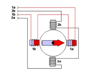
06/27/2022 at 20:24 • 0 commentsTo rotate a bipolar stepper motor, pulses are applied in sequence to the windings, the sequence of these pulses, are applied externally with an electronic controller. Said controllers are designed in such a way that the motor can be kept in a fixed position and also so that it can be rotated in both directions.
![]()
There are three characteristics that are common in stepper motors:
- Voltage: Stepper motors have a working electrical voltage. This value is printed on its case or is at least specified on its datasheet.
- Electric resistance: This resistance will determine the current that the motor will consume and its value affects the torque curve of the motor and its maximum operating speed.
- Degrees per step: This factor defines the number of degrees the axis will rotate for each full step.
Here is a quick guide for Stepper Motor Wire Color And Coil Pairs.
However, color codes are not always respected by manufacturers. So a test allowed me to find that my stepper motor works at 5 volts. I also found by means of an ohmmeter the two coils and the order of the pins as follows:
- pin 1 - gray
- pin 2 - yellow
- pin 3 - brown
- pin 4 - red
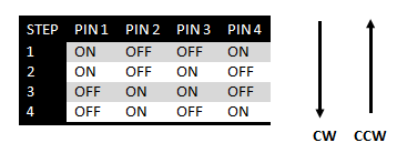
These motors have several windings that, to produce the advance of a step, must be fed in a suitable sequence. By reversing the order of this sequence, the motor turns in the opposite direction. The next table shows the sequence to generate the CW (Clockwise) and CCW (Counterclockwise) movements of a bipolar motor.
![]()
-
2. Build and Wiring the Mini Elevator
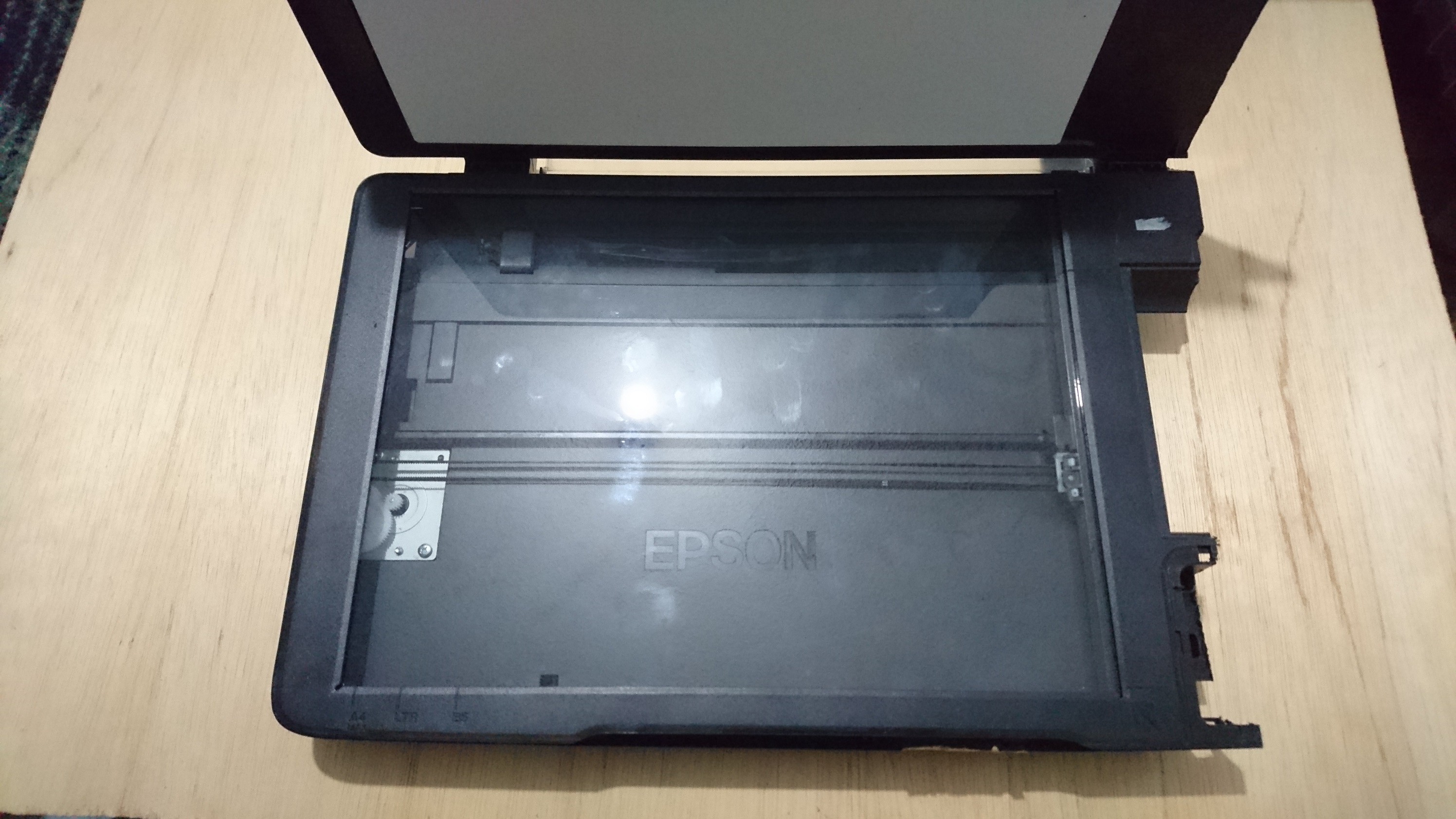
06/27/2022 at 20:20 • 0 commentsI got the stepper motor from an old printer scanner that I'm recycling.
![]()
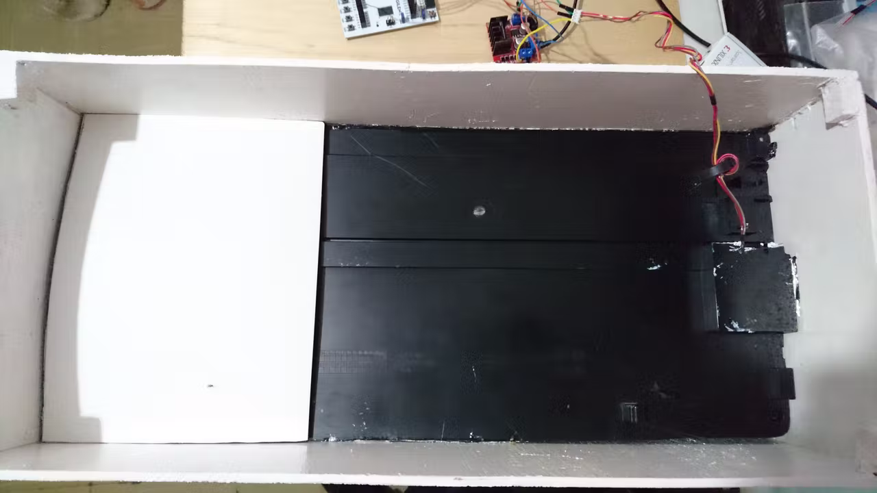
In fact, I took advantage of the entire mechanism and adapted it to a wooden box that I built from recycled wood.
![]()
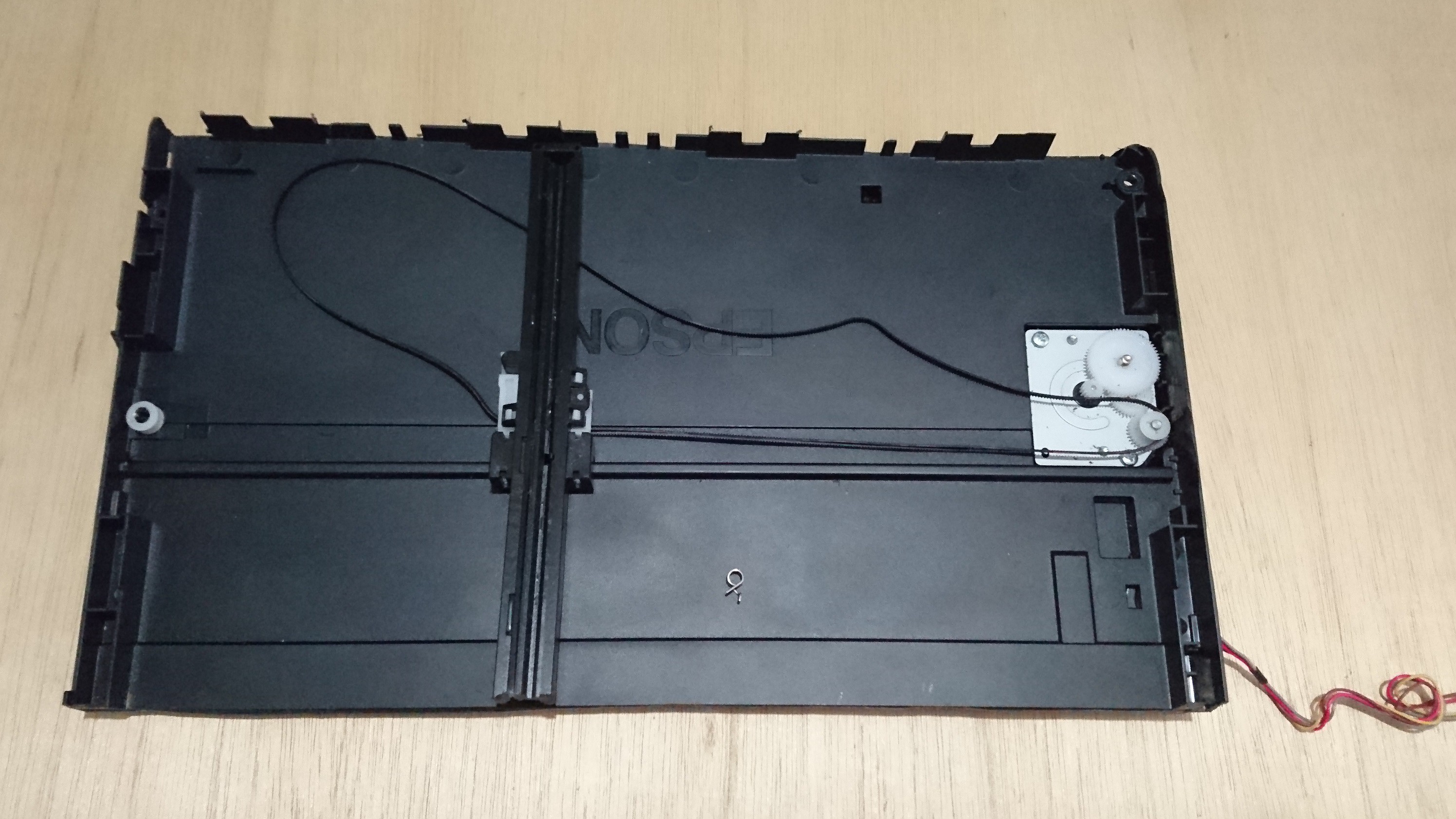
In the image below you can see the scanner mechanism adapted to a wooden box (back view).
![]()
The front view of the mini elevator is shown in the figure below. The wooden box has the next dimensions: 20 cm (width) x 20 cm (depth) x 45 cm (height).
![]()
I assembled this prototype with screws in its corners, then added white glue and silicone. The elevator cabinet is made of thick cardboard to reduce weight and give it strength, and it has next dimensions: 17 cm (width) x 8 cm (depth) x 14 cm (height). In all this I spent two days because the prototype had to be painted.
-
1. Hardware
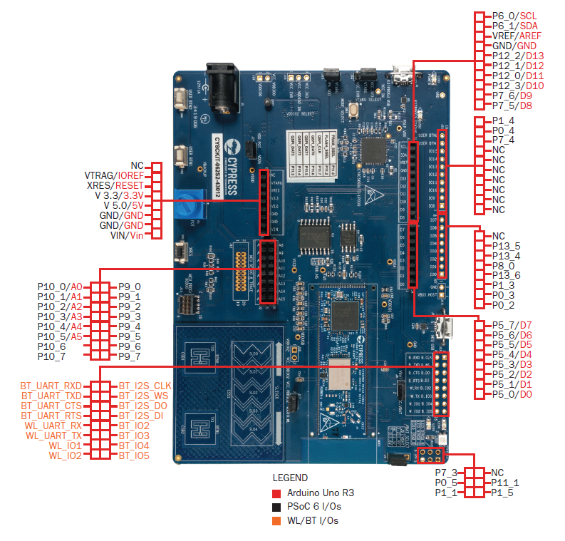
06/27/2022 at 20:12 • 0 commentsThe PSoC™ 62S2 Wi-Fi BT Pioneer Kit(CY8CKIT-062S2-43012) is a low-cost hardware platform that enables design and debug of the PSoC™ 62 MCU and the Murata 1LV Module (CYW43012 Wi-Fi + Bluetooth Combo Chip).
Features:
- CY8CMOD-062S2-43012 carrier module that contains: a) PSoC 6 MCU (CY8C624ABZI-S2D44), and b) Murata 1LV ultra-small 2.4/5.0-GHz WLAN and Bluetooth functionality module based on CYW43012
- 512-Mbit external Quad SPI NOR Flash that provides a fast, expandable memory for data and code
- 4-Mbit Quad SPI ferroelectric random-access memory (F-RAM)
- KitProg3 onboard SWD programmer/debugger with USB-UART and USB-I2C bridge functionality
- CapSense touch-sensing slider (5 elements), two buttons, based on self-capacitance (CSD) and mutual-capacitance (CSX) sensing
- A micro-B connector for USB device interface for PSoC 6 MCU
- 1.8 V and 3.3 V operation of PSoC 6 MCU is supported
- Two user LEDs, an RGB LED, two user buttons, and a reset button for PSoC 6 MCU
- A potentiometer
- One Mode selection button and one Status LED for KitProg3
- A microSD Card holder
![]()
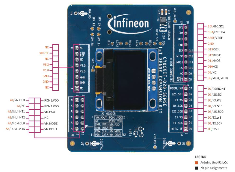
The IoT sense expansion kit is a low-cost Arduino™ UNO compatible shield board that can be used to easily interface a variety of sensors with the PSoC™ 6 MCU platform, specifically targeted for audio and machine learning applications.
Features:
- Digital XENSIV™ MEMS Microphone(s)
- Digital XENSIV Barometric Air Pressure Sensor
- Bosch 9-axis Absolute Orientation Sensor
- Piezo MEMS Analog Microphone
- Audio Codec and headset jack
- OLED Display Module
![]()
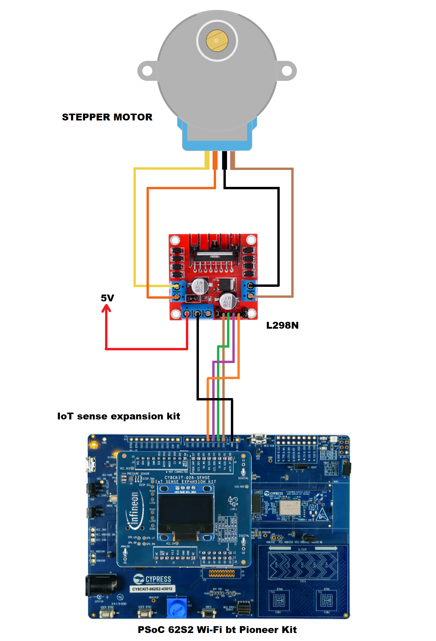
Now I show you the electrical diagram of the circuit that we assembled below.
![]()
Smart Mini Elevator
Old scanner hacked and turned into smart mini elevator