Close
0%
0%

21 Band Audio Spectrum Analyzer

Completed

Public Chat
Similar projects worth following
21-Band Audio Spectrum Analyzer using ESP32 controller together with a set of three MSGEQ7 ICs for the 21 frequencies and 21 strips of 20 LEDs WS2812B for a total of 420 LEDs. Audio Amp and Bluetooth are optional.

This project started as a hobby using a generic 14-bands spectrum analyzer based on Arduino AT-Mega, and converting it to a 21-bands audio spectrum analyzer now running on ESP32 with more memory for additional color patterns and features. New hardware includes the low cost 2x 3watts Audio Amp and Bluetooth connectivity. 

The biggest challenge was making the LED bezel / 20x 21 LED array. I ordered separate vertical columns for the LED strips to stick on, and then solder the two ends to 3-pin terminals. I also ordered the 2 horizontal PCBs that holds the 21 columns and distributes power to all 420 LEDs .. Using the LED Strips with the PCB was the easiest way I could think of without having jumper wires between the 21 columns .. 

A second variant, which I will try in the upcoming weeks, is to hand solder the 420 LEDs individually which will save me about $40 and will look much nicer. I will try and use low temperature solder paste (138degC) and a heat gun to blow hot air from below the PCB. I'm not sure is going to work, but using a hot-plate will be even more challenging.

Gerber_21-Bands-Audio-Spectrum-Analyzer-Simp_PCB-21-Bands-Audio-Analyzer-Simple_2025-10-30.zip

Artwork Files. Order boards at: jlcpcb com

x-zip-compressed - 200.85 kB - 10/30/2025 at 22:22

Download

Spectrum_Analyzer_21x16_Red_ESP32.zip

SKETCH in Arduino IDE - using a 21 x 16 matrix display panel.

x-zip-compressed - 1.41 MB - 10/30/2025 at 22:19

Download

Spectrum_Analyzer_21x20_Red_ESP32.zip

SKETCH in Arduino IDE - using a 21 x 20 matrix display panel.

x-zip-compressed - 1.36 MB - 10/30/2025 at 22:17

Download

Assembly_Top.PNG

Assembly Drawing

Portable Network Graphics (PNG) - 249.26 kB - 05/24/2023 at 03:34

Preview

Schematic_21Ch Analyzer ESP32 - Full_2023-05-14.pdf

Schematic Diagram in PDF

Adobe Portable Document Format - 142.44 kB - 05/15/2023 at 00:52

Preview

View all 7 files

  • 1 × ESP32 38pin Type-C Dev-board Expressif
  • 1 × Si5351 Skyworks Clock generator - SparkFun
  • 3 × MSGEQ7 7 Band Audio Spectrum Analyzer IC
  • 1 × M18-HX8 Bluetooth - OPTIONAL
  • 1 × PAM8403 Audio ICs / Audio Amplifiers - OPTIONAL

View all 22 components

View all 2 project logs

  • 1
    Order your parts and wait 3-4 weeks.

    1. Order boards JLCPCB.com (black soldermask finish).

    2. Order parts AliExpress or Amazon and for MSGEQ7 go to Mouser.com to avoid fake ICs.

    3. Order LED strips from BFT-Lighting.com or whatever works for you but be consistent. Do not mix and match or you get some weird colors from different suppliers. (I got 5 rolls of the 74/m black IP30 for about $65).

  • 2
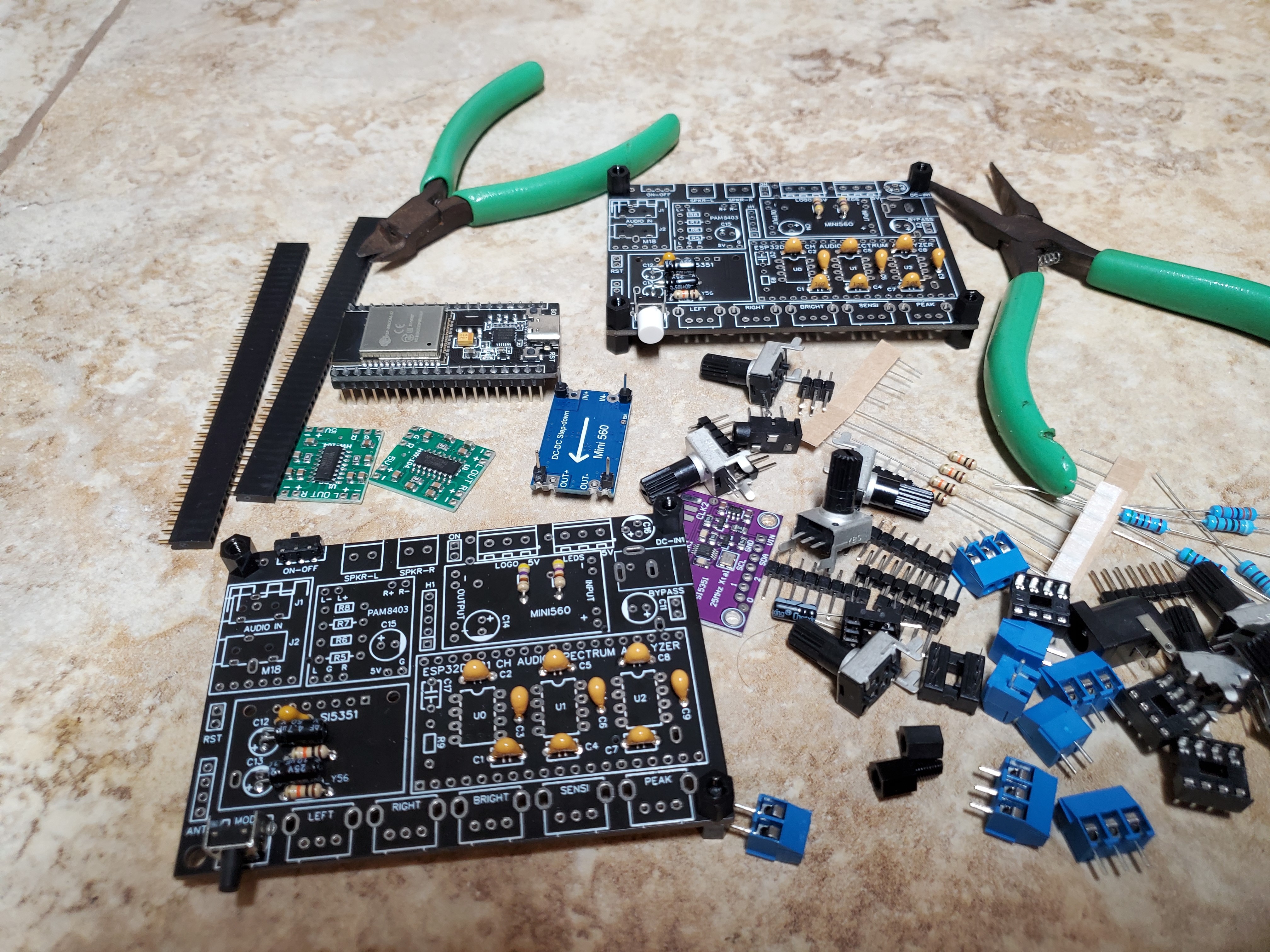
    Solder components to the board top side.

    Solder smaller components first such as the ceramic caps and resistors. Resistors R5, R6, R7 and R8 are only needed if you plan on adding buttons for the Bluetooth such as next / previous. 

    Also don't solder C17 and R9 (only needed for internal clock single 7 channel mode). Next solder the larger electrolytic caps with polarity markings (C12, C13, C14, C15 will be soldered axially on a 90 degree angle). Mount and solder Jacks J1 and J2, will come handy if using a 3.5mm audio line input.  For U0, U1, U2 it's up to you if you want to use an 8-pin DIP socket for mounting the MSGEQ7 ICs. Complete by soldering the rest of the parts.

    Here is the Assembly Drawing (top side).

  • 3
    Ignore the parts on the board bottom side.

    The bottom side components are intended for advanced players. Mainly if you intend to mount everything in a housing resembling a portable speaker, in which case having the extra batteries might come in handy. Use a 2-pin jumper on header Bypass the charging circuit and power directly from 12v. Also make sure header 'ON' gets a jumper if you want the LEDs to come on.

View all 7 instructions

Enjoy this project?

Share

Discussions

TM Russell wrote 07/18/2026 at 03:47 point

I have not completed this project 😒  I ordered all the parts needed and finally found a thick piece of plexiglass that would be enough to make it. The issue is finding someone to laser cut the pieces for me. My local community college has a cnc laser, but its not big enough for the pieces needed. I was looking into other designs that use single pieces stacked on threaded rod, but never started this project back up.

  Are you sure? yes | no

meuviolino wrote 07/26/2026 at 01:03 point

Okay, but could you answer the four questions I asked the project author below? I didn't get any answers.

  Are you sure? yes | no

meuviolino wrote 07/01/2026 at 22:12 point

Olá Sam! Primeiramente, obrigado por compartilhar seu excelente projeto. Tenho algumas perguntas:

1) Nunca fiz um pedido em "jlcpcb.com" antes, então gostaria de saber qual arquivo do seu projeto devo enviar para que as placas sejam fabricadas.

2) Dentro da pasta zip "Gerber_21-Bands...", existem 11 arquivos; Eles sabem o que usar ou especificar algo preciso? (Devo enviar a própria pasta zip?)
3) O conteúdo da pasta Gerber funciona para ambos os projetos — "Spectrum_Analyzer_21x20_Red_ESP32" e "Spectrum_Analyzer_21x16_Red_ESP32" — ou você recomenda usar a versão "21x20"?
4) Em vez de 20 LEDs na vertical, gostaria de usar 10 LEDs — especificamente 5 verdes, 3 laranjas e 2 vermelhos, de baixo para cima; é possível alterar isso no código?
Desculpe pelas muitas perguntas. Muito obrigado.

Daniel - do Brasil

  Are you sure? yes | no

samm928 wrote 07/28/2026 at 14:45 point

Gerber files are also called Artwork Files if you need to order boards. Bin files are easy to flash/upload to your esp32, since the library is already compiled. If you need to change the sketch, then you need to make sure to select the right library for FastLED and also esp32 board file V3 core or previous  to 3.0.5 build releases.

****************************************************************************************
*  Libaries and external files  * IMPORTANT * USE ESP32 Boards LIBRARY ver.3.0.5  * IMPORTANT *
*****************************************************************************************/
#include <Adafruit_SI5351.h>                   // Adafruit_SI5351 version 1.2.1
#include <FastLED_NeoMatrix.h>            // FastLED version 3.7.6 (optimized to 

  Are you sure? yes | no

meuviolino wrote 07/30/2026 at 23:03 point

Thanks, Sam.

  Are you sure? yes | no

TM Russell wrote 07/02/2025 at 02:15 point

I plan on making this one! I already ordered the pcb's. I love how you laid all the boards out, that was clever. The only thing I wish you had done would be to make the front controls on a separate pcb for easier mounting, but its not a deal breaker. I can wire the on/off switch to the front. Thank you for sharing this awesome project! 

  Are you sure? yes | no

meuviolino wrote 07/17/2026 at 23:17 point

Hello TM Russell, how are you? Did you complete your project?
Perhaps you could answer the questions I asked above?
I haven't received a response from the project author. Thanks.

  Are you sure? yes | no

samm928 wrote 07/28/2026 at 14:51 point

This is an older version using the 38-pin esp32 dev board, even though most of the GPIOs are unused. Since then I re-designed the PCB for a smaller ESP32-Zero (18-pin version from Waveshare), but it requires a hot-plate to solder the components. If you sign up for EasyEDA, you'll be able to view the latest board design.

  Are you sure? yes | no

Sebastian.Anantham wrote 10/31/2023 at 13:51 point

Very nice and hypnotic spectrum analyser 

  Are you sure? yes | no

Similar Projects

Does this project spark your interest?

Become a member to follow this project and never miss any updates