 samm928
-
1Order your parts and wait 3-4 weeks.
1. Order boards JLCPCB.com (black soldermask finish).
2. Order parts AliExpress or Amazon and for MSGEQ7 go to Mouser.com to avoid fake ICs.
3. Order LED strips from BFT-Lighting.com or whatever works for you but be consistent. Do not mix and match or you get some weird colors from different suppliers. (I got 5 rolls of the 74/m black IP30 for about $65).
![]()
-
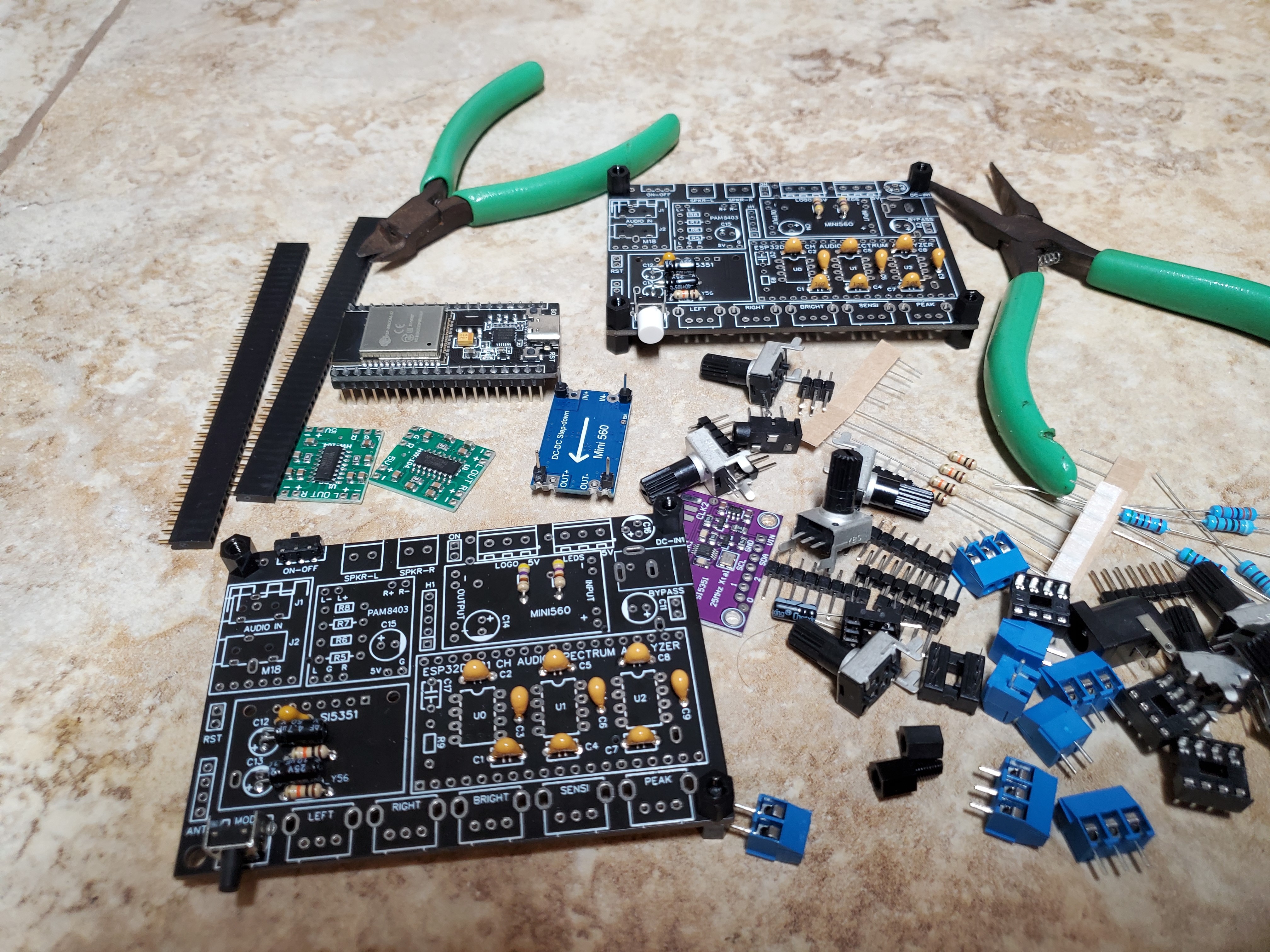
2Solder components to the board top side.
Solder smaller components first such as the ceramic caps and resistors. Resistors R5, R6, R7 and R8 are only needed if you plan on adding buttons for the Bluetooth such as next / previous.
![]()
Also don't solder C17 and R9 (only needed for internal clock single 7 channel mode). Next solder the larger electrolytic caps with polarity markings (C12, C13, C14, C15 will be soldered axially on a 90 degree angle). Mount and solder Jacks J1 and J2, will come handy if using a 3.5mm audio line input. For U0, U1, U2 it's up to you if you want to use an 8-pin DIP socket for mounting the MSGEQ7 ICs. Complete by soldering the rest of the parts.
![]()
Here is the Assembly Drawing (top side).
![]()
-
3Ignore the parts on the board bottom side.
The bottom side components are intended for advanced players. Mainly if you intend to mount everything in a housing resembling a portable speaker, in which case having the extra batteries might come in handy. Use a 2-pin jumper on header Bypass the charging circuit and power directly from 12v. Also make sure header 'ON' gets a jumper if you want the LEDs to come on.
-
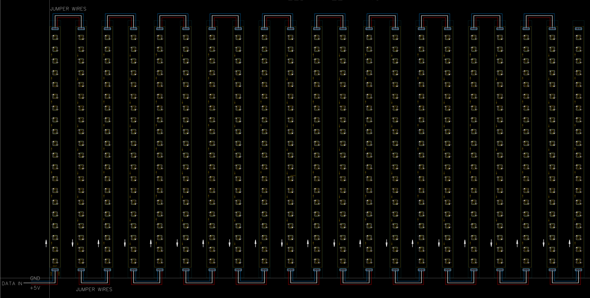
4Making the 21-band Panel Array for LEDs
Making the panel-array is anybody's guess on what would work best if you don't intend on spending a of money. You can use a cardboard to add the LED strips and hide the wiring behind the cardboard. Either way, you still have to solder at least 4 points on each of the 21 bar segments (2 for power and 2 for data-in / data-out).
![]()
-
5Mounting the LED strips on 'dummy' PCBs
For me this solution came in handy, although the 'dummy' boards are actually functional PCBs if someone had the patience and steady hand to solder 420 SMD5050 leds to the boards not to mention 420 capacitors for the WS2812B chips of each pixel. To save time and burnt fingers, lets assume we stick a strip of 20 LEDs to each dummy PCB and just solder the ends of vertical columns in red, to the horizontal PCBs in green. Should look something like this:
![]()
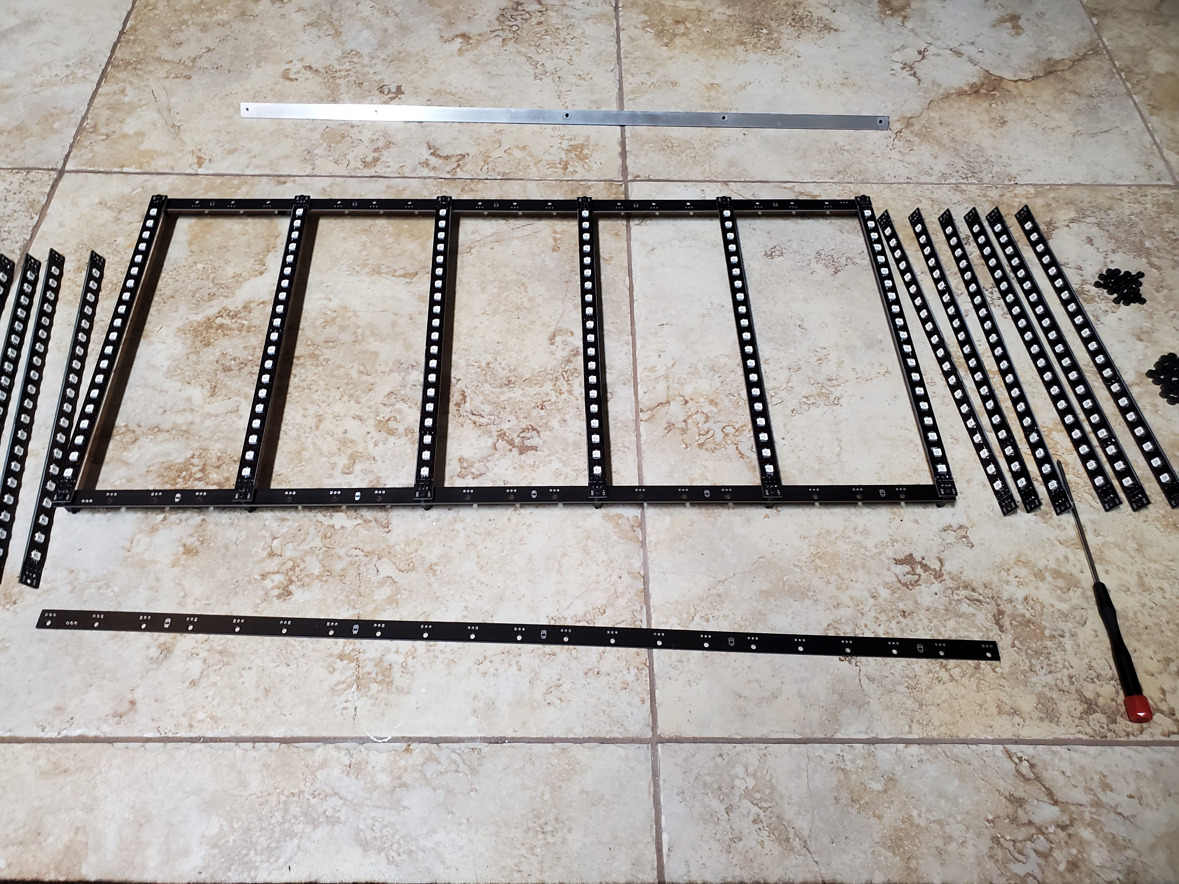
Making the individual vertical columns (21 strips in total) ..
![]()
Use M3 nylon hardware (9mm long screws and 3mm spacers) to mount the 21 column PCBs to 2 the horizontal PCBs to hold them in place. Make sure you daisy-chain arrows match and the segments light up before soldering each column.
![]() The two horizontal top and bottom rail PCBs will connect the 5v Supply and the Data between all 21 vertical columns without the need for jumper wires. With a little luck it will look something like this when it's done ..
The two horizontal top and bottom rail PCBs will connect the 5v Supply and the Data between all 21 vertical columns without the need for jumper wires. With a little luck it will look something like this when it's done .. ![]()
-
6Full LED Panel-Array assembly
This final step is still ongoing, since I decided to buy a roll of 500 pixels SMD5050 and see if I can use a low temperature solder-paste mix (138deg.C) and a hot-air gun blowing from behind the PCB to try and solder the LEDs directly to the vertical column boards. This method would save around $50 in LED cost and will have a uniform spacing between pixels if the columns are to be used with block acrylic diffusers.
-
7Final Step .. Acrylic
These sections are not going to be 3D printed, most likely CO2 laser cut for a fee, and have them shipped home assuming is worth the cost (post pandemic prices) and the effort.
![]()


 The two horizontal top and bottom rail PCBs will connect the 5v Supply and the Data between all 21 vertical columns without the need for jumper wires. With a little luck it will look something like this when it's done ..
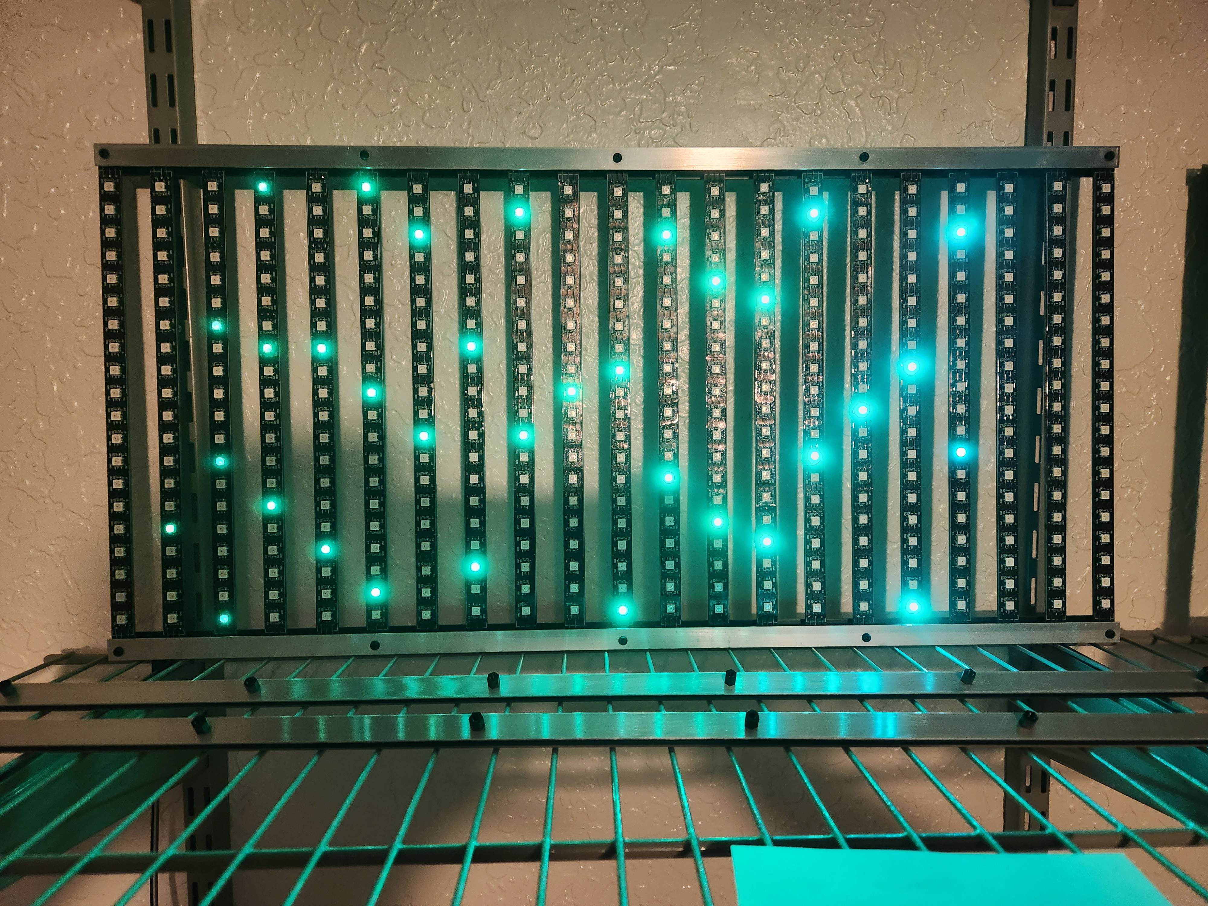

Discussions
Become a Hackaday.io Member
Create an account to leave a comment. Already have an account? Log In.