-
Muffsy Constant Current LED Tester with Meters
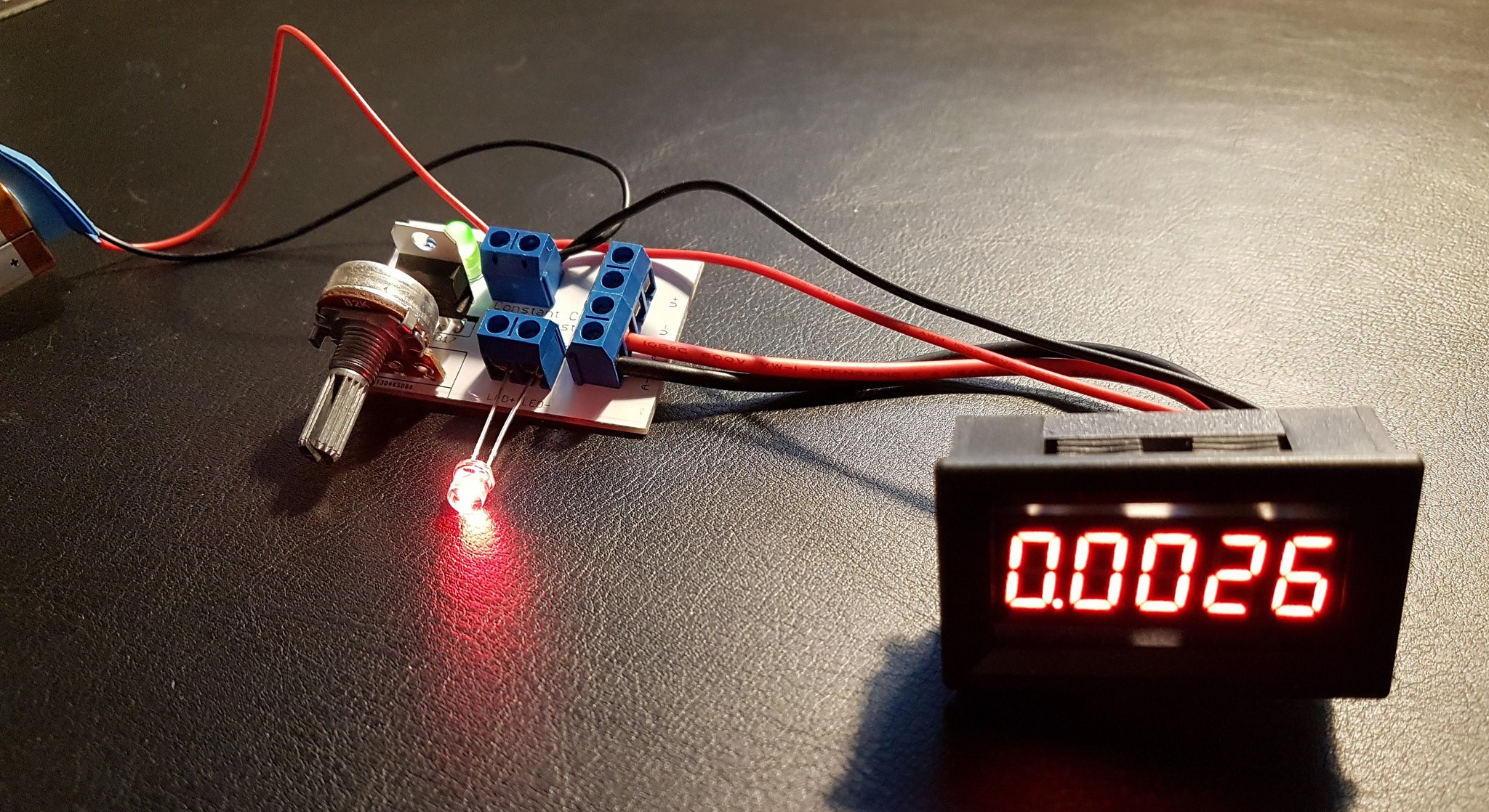
10/23/2017 at 10:35 • 0 commentsMeters are installed, I still need to mount the project in a suitable enclosure.
I got enough resistance at 2K, so I replaced the 10K potmeter for better accuracy.
First test with the ammeter, showing 2.6 mA:
![]()
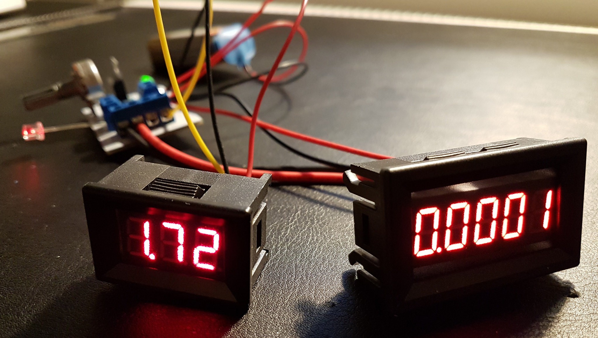
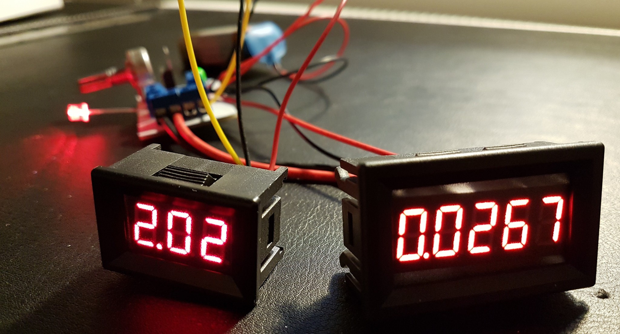
Voltmeter installed. The forward voltage drop varies from 1.72 volts at 0.1 mA, to 2.02 volts at 26.7 mA for this particular LED.
![]()
![]()
LEDs rarely experience any adverse affects by feeding them with < 30 mA. Even when mounted the wrong way around. My max value is ~27 mA.
Eagle Project Files
The Eagle project files and Gerbers have been updated with the new component values.
![]()
-
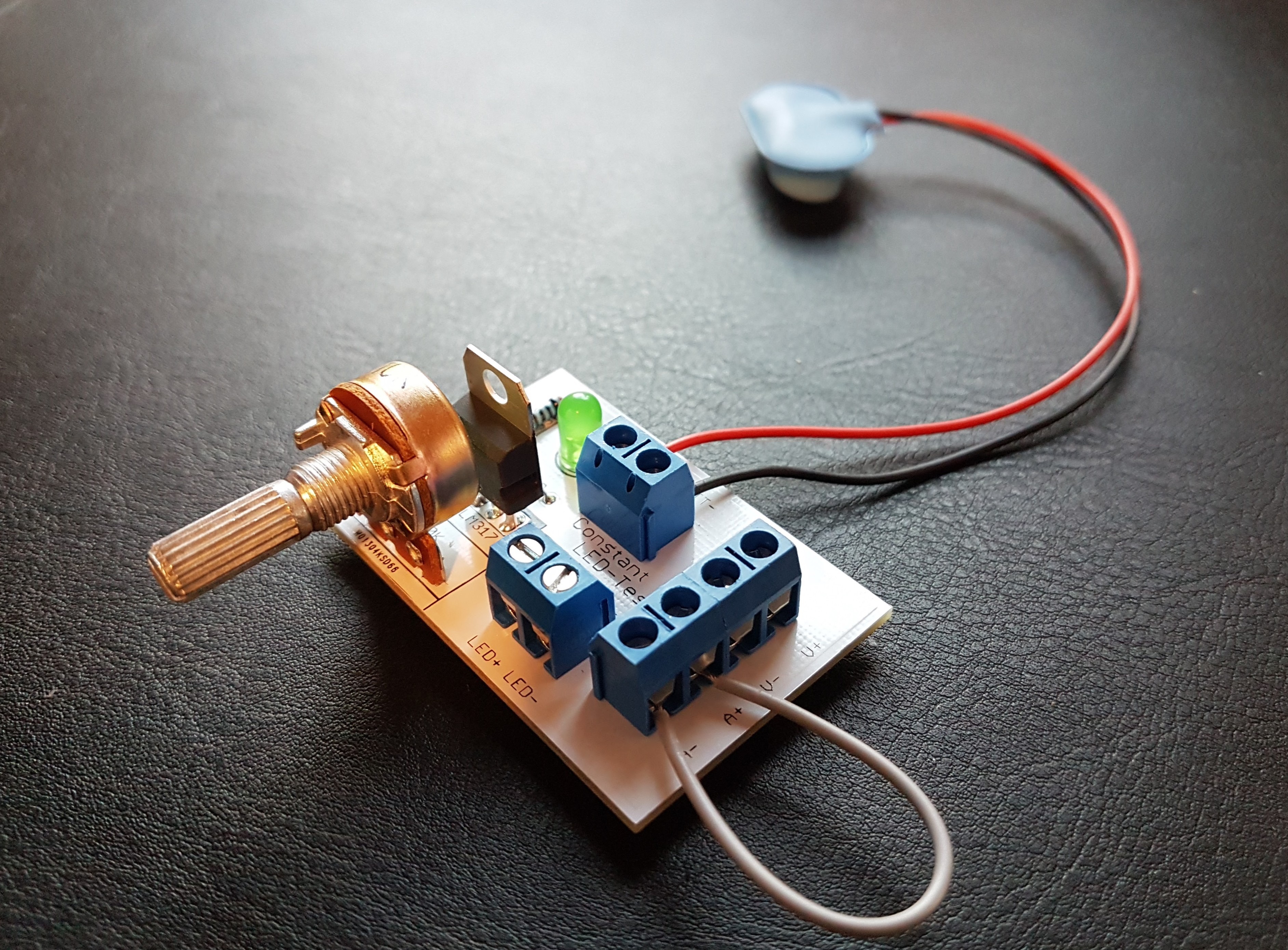
LED-Tester Finally Built
10/13/2017 at 07:03 • 0 commentsLooking good, and it works great!
![]()
-
Ampere and Voltmeters for the Constant Current LED Tester
10/11/2017 at 09:10 • 0 commentsYou can of course just use your multimeter for this, These are great if you want to build the project in an enclosure, making it completely stand-alone.
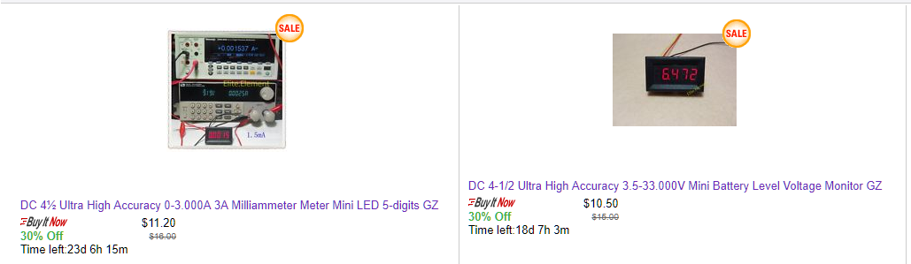
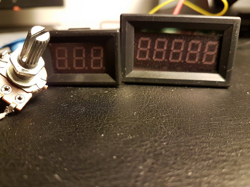
The "Ultra High Accuracy" ampere and voltmeters from eBay seller elite.element seem to be a great fit for this project:
http://stores.ebay.com/Elite-element/_i.html?_nkw=accuracy&submit=Search&_sid=897140872
![]() Basically, I found the milliammeter very suitable and found a matching voltmeter.
Basically, I found the milliammeter very suitable and found a matching voltmeter.I have no affiliation with the seller, but I have ordered these.
-
New version, with connectors for voltmeter
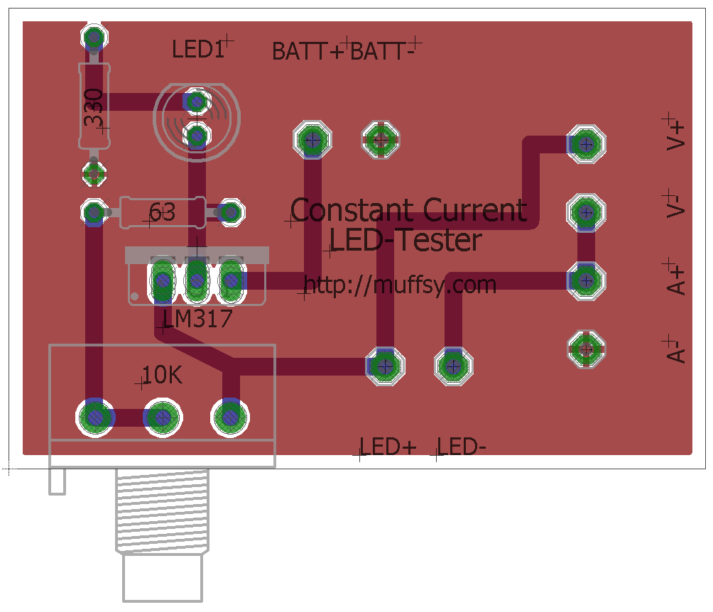
09/20/2017 at 09:17 • 0 commentsIt's been a while since I thought about this project, but now I want to have the boards manufactured. And I want connectors for the voltmeter.
This is what's been ordered, the size of the board is 52x35 mm.:
![]()
![]()
![]()
The new design has been uploaded to the files section of this project. The zip-file (LED-tester3.zip) contains Eagle project files and Gerbers.
-
Meters, Learning about LEDs and a Deluxe Version
07/20/2017 at 10:37 • 2 commentsMeters
A voltmeter and ammeter should give all the necessary information about my "LUT" (LED Under Test):
![]()
- The ammeter in series with the LED will give you the required current (If)for your selected brightness.
- The voltmeter in parallel with the LED will give you the forward voltage drop (Vf) at that current level.
Then, knowing the voltage of your circuit (Vc) will give you the following formula for deciding your resistor value (R):
R = (Vc - Vf) / If
Recap
Just a short recap on how an LED works before I continue. LED brightness is not controlled by how much voltage you feed it with, rather by how much current is running through it. To get the brightness you want, you adjust the current with a current limiting resistor according to Ohm's law (R = U / I)
The voltage (U) is the difference between your circuit voltage and the voltage drop in the LED. The current (I) is the current needed for the brightness you want. The voltage drop is (almost) always stated as a single voltage. Knowing the current, your circuit voltage and the voltage drop, you can use a calculator to find the resistor value.
So, know what voltage your circuit runs on, know the brightness you want, and find the LED's voltage drop and stuff it in a calculator (or use the formula above). Not too much work, right? Turns out I've been wrong for all these years.
Learning about LEDs
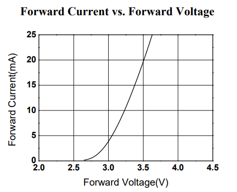
I noticed that the forward voltage drop decreased at lower currents, so I got to read my very first LED datasheet. Here's a graph from a random LED datasheet that confirms what I saw:
![]()
On one of my cheap Chinese LED's had a variation in forward voltage drop from 1.6 to 2.6 volts. The result at lower brightness (i.e. lower current) is:
- The voltage across the current limiting resistor is higher...
- ...which means that the circuit's current is higher.
- Higher current means more brightness.
There's the explanation for why I always need higher value resistors than I expect at lower brightness.
This really made this LED Tester more useful, as it turns out that the formula for selecting the correct resistor value is really more of a guesstimate. (You can of course get it right by buying more expensive LEDs and getting the correct datasheet. Still, there's no substitution for actually seeing the brightness.)
LED Tester, Deluxe version
Blogger theslowdiyer in Denmark has made a deluxe version of this LED Tester, complete with drawings:
https://theslowdiyer.wordpress.com/2017/03/22/led-tester-deluxe/
![]()
(Picture courtesy of https://theslowdiyer.wordpress.com)
-
Getting Low Current from LM317
11/29/2016 at 21:49 • 4 commentsThe discussion in the previous log showed that I'll never get less than 2-3 mA from an LM317, as that is the minimum current it can provide while still regulating. (Discussion here: https://hackaday.io/project/18624-muffsy-constant-current-led-tester/log/49640-testing-my-leds#discussion-list)
I looked for a way to make sure there was a current draw, while still allowing me to adjust the current to the "LUT" (LED Under Test), and found this: http://electronics.stackexchange.com/questions/211249/lm317-µa-constant-current-source-possibility
An LED from LM317's power output to ground acts as a load and draws current from the voltage regulator. Some 4 mA would be sufficient.
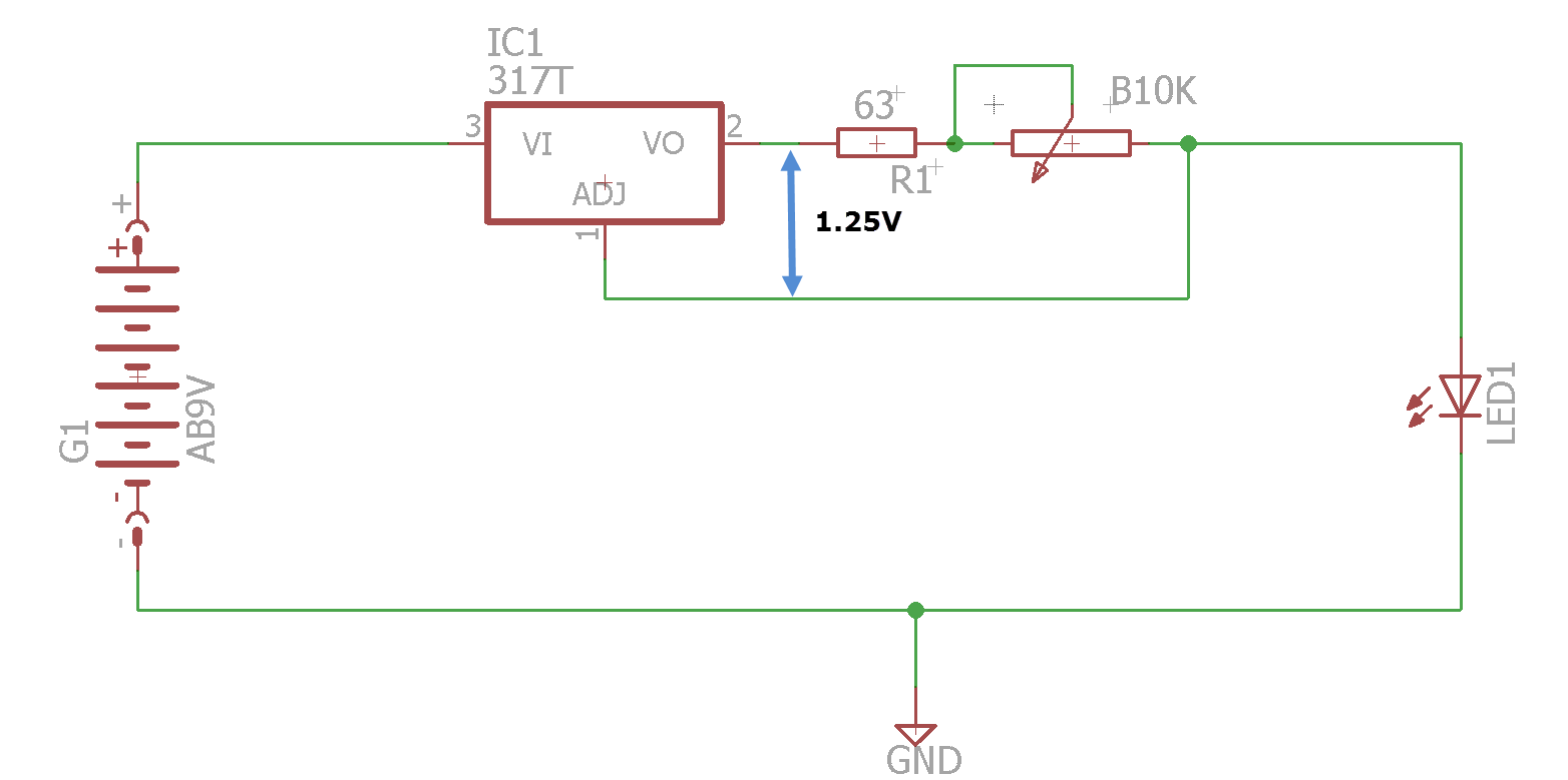
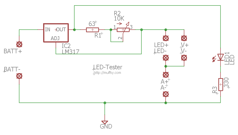
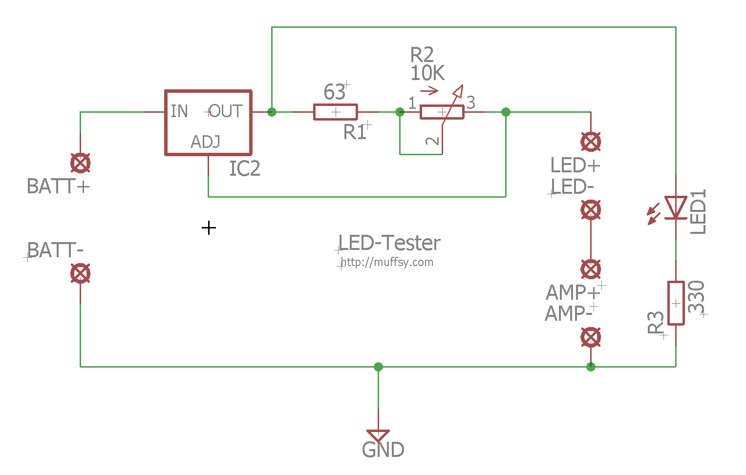
Here's the updated schematic:
![]()
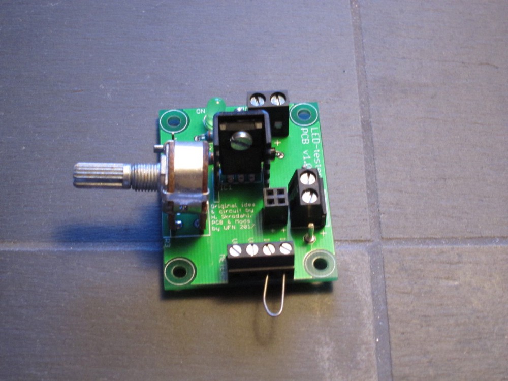
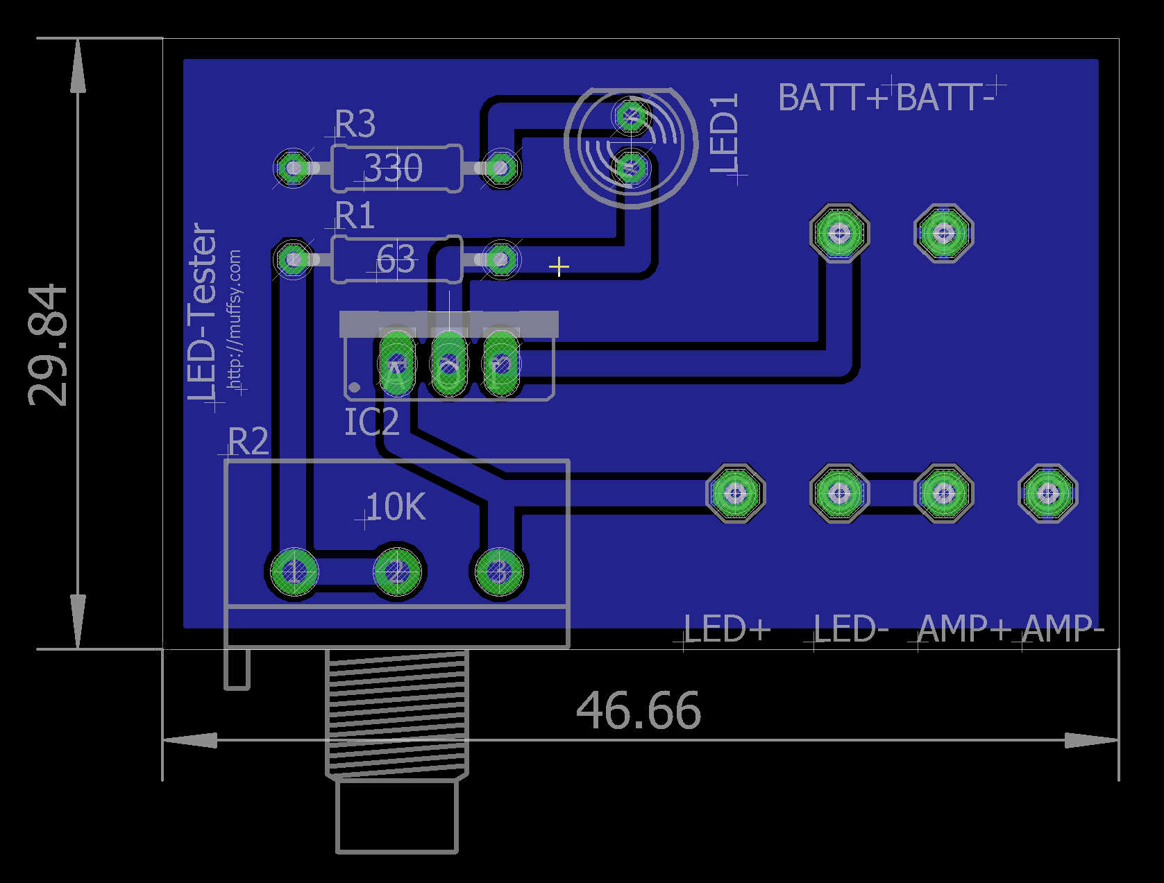
Here's a PCB with the new circuit, the Eagle files have been replaced with this version:
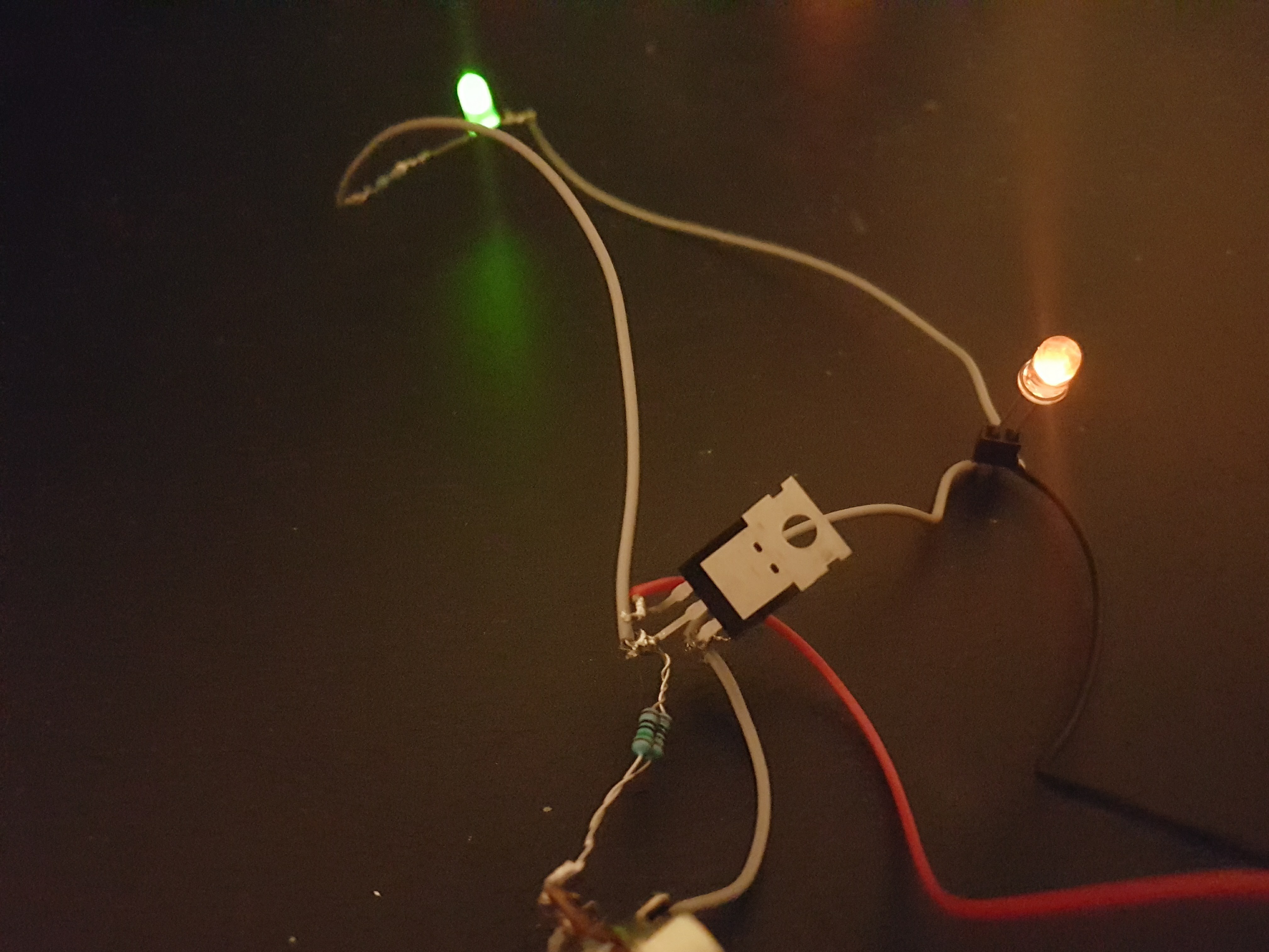
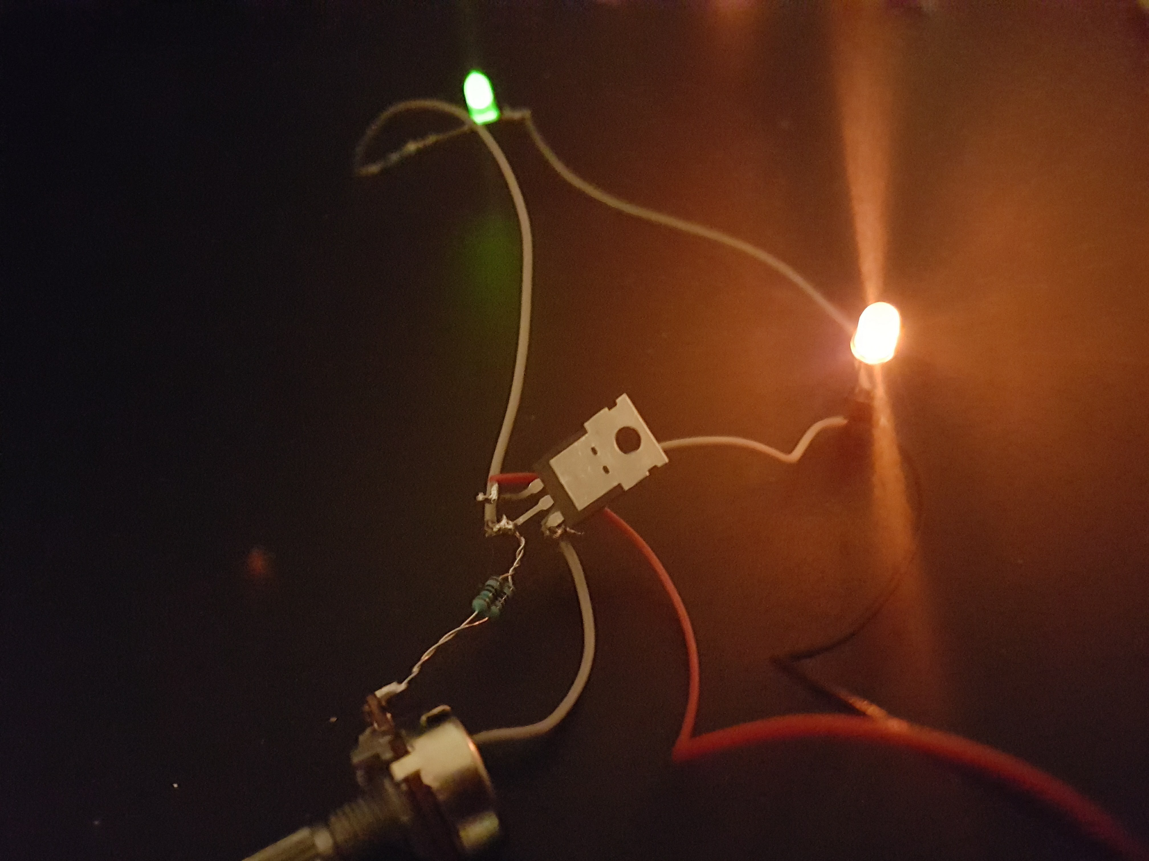
![]() The pictures didn't come out particularly well, as the highest brightness gave a lot of glare and the lowest brightness seems brighter than it really is.
The pictures didn't come out particularly well, as the highest brightness gave a lot of glare and the lowest brightness seems brighter than it really is.Lowest brightness (it's barely visible in real life):
![]()
Highest brightness (pretty darn bright):
![]()
-
Testing My LEDs
11/28/2016 at 12:14 • 10 commentsLEDs keep accumulating, and they are spread around in my work space. Most of them are clear, see-through LEDs. Some are dead (either by abuse, or because they are cheap Chinese diodes).
Most of them are high intensity LEDs, and they often need below 1 mA so they won't blind me.
In other words:
I need a way to test my LEDs to see if they work, which color they are, and find a suitable brightness.After having used the LM317 in various projects, I had noticed that it could be used as a constant current source. This got me thinking about using it with LEDs.
Here's the circuit I came up with:
![]()
Forget for a moment that the pinout on the regulator is wrong (the attached Eagle project files are correct). Here's how it works:
- The LM317 will always keep a 1.25V reference voltage between the output and the adjust pins. Adding resistance in this loop will generate a constant current.
- I want to limit the current to a maximum of 20 mA. Knowing that, and the voltage (1.25V), using Ohm's law will give me the correct resistor: U/I = R -> 1.25/0.02 = 62.5 ohms. I settled for 63 ohms which is close enough.
- Adding 10k ohms will give a minimum current of 1.25 mA, so I put a 10k potentiometer in the loop as well. There's a linear pot in the picture above, a logarithmic one will work better.
- An amperemeter can be hooked up in series with the LED, to see what the current is.
- A voltmeter can be hooked up in parallel with the LED, to see the forward voltage drop.
- Using these two parameters, you can get the desired brightness in any circuit. Use Ohm's law or one of the many online LED calculators.
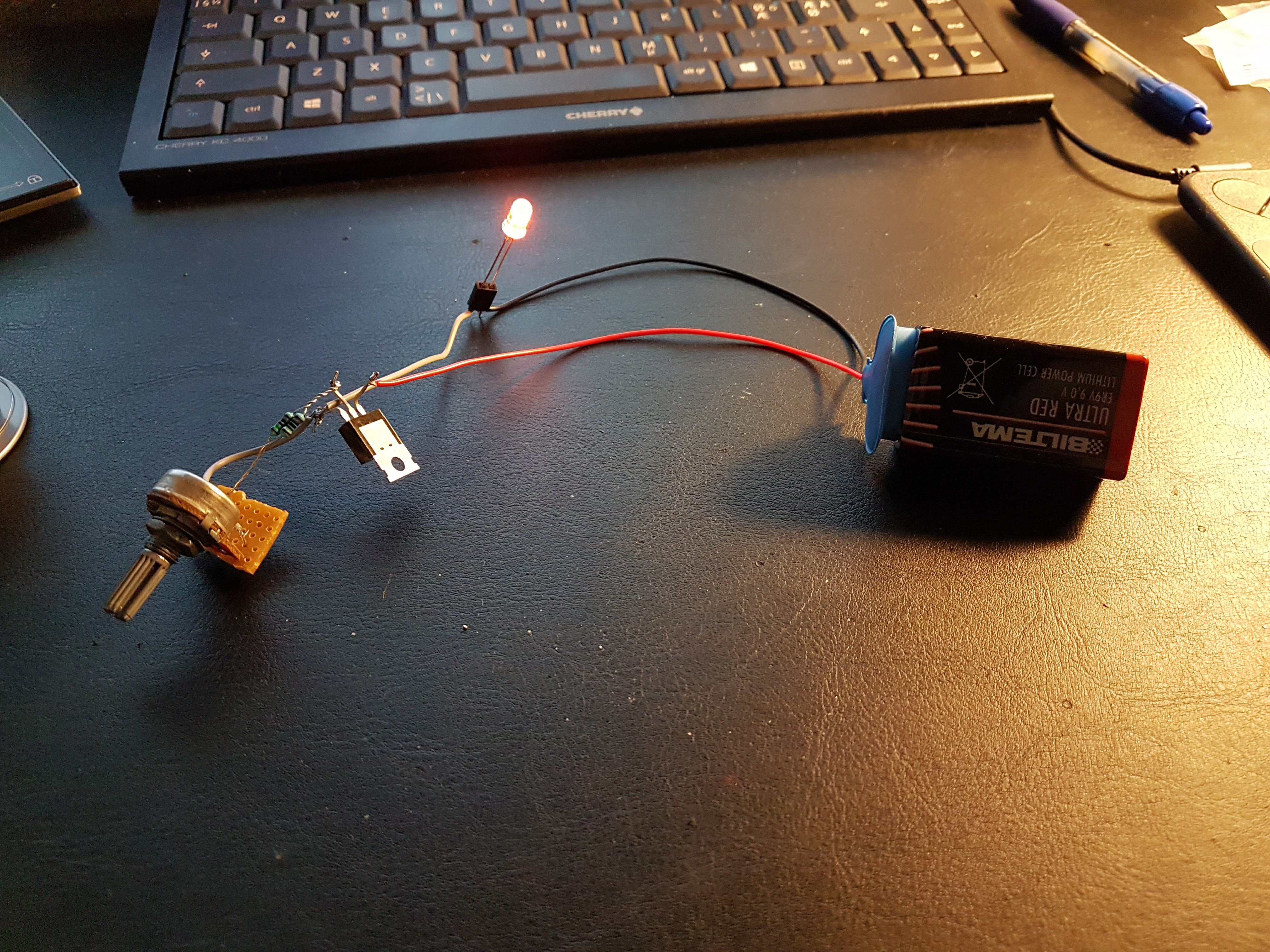
I built it, and it works.
The linear pot that I used makes the LED go darker relatively fast, a logarithmic one is better.
![]()
- The LM317 will always keep a 1.25V reference voltage between the output and the adjust pins. Adding resistance in this loop will generate a constant current.
Muffsy Constant Current LED Tester
Open Source, Versatile LED Tester with Eagle Project Files
 Basically, I found the milliammeter very suitable and found a matching voltmeter.
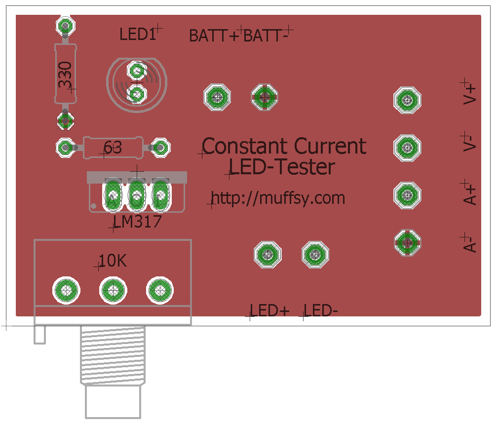
 The pictures didn't come out particularly well, as the highest brightness gave a lot of glare and the lowest brightness seems brighter than it really is.