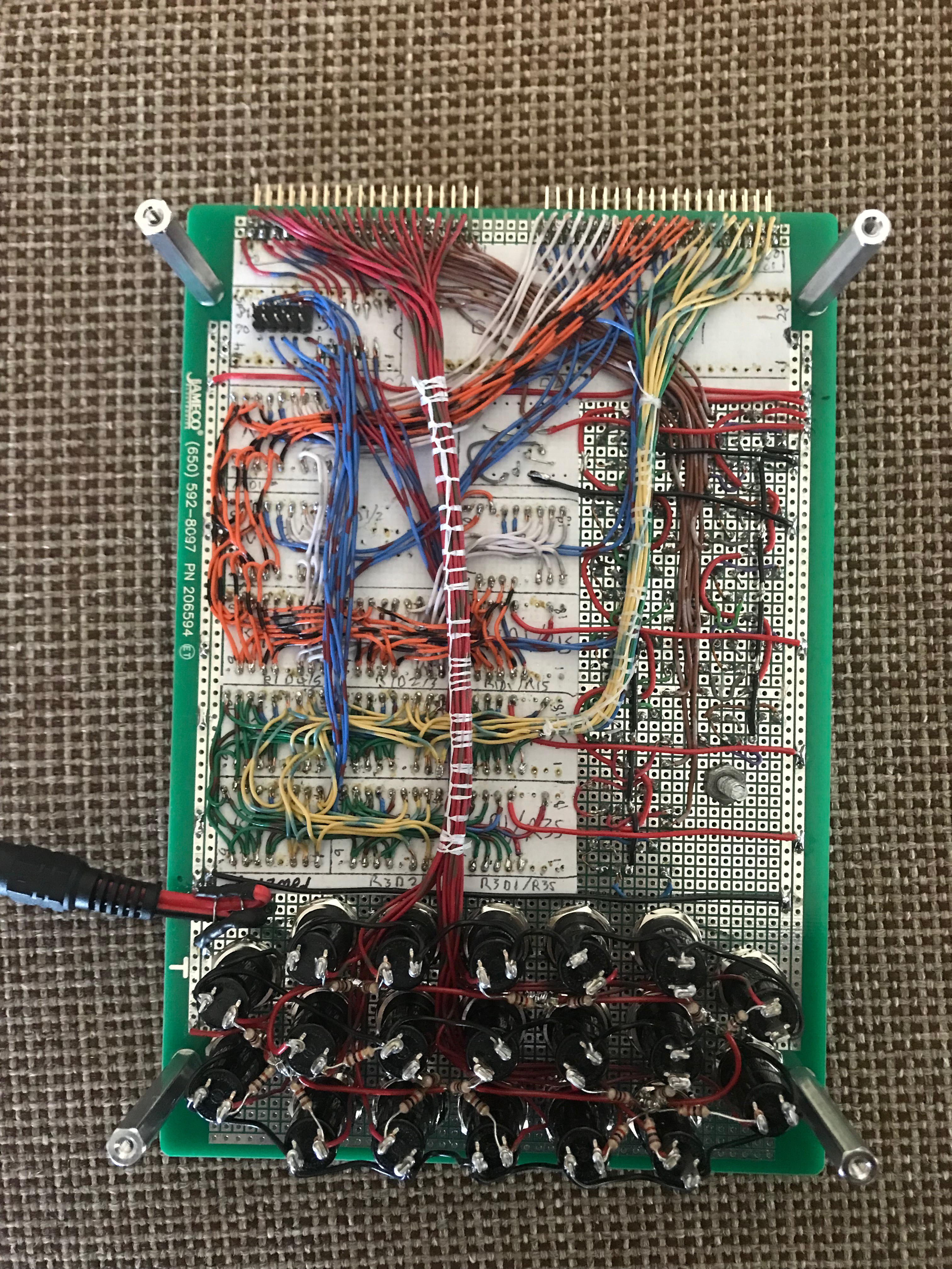
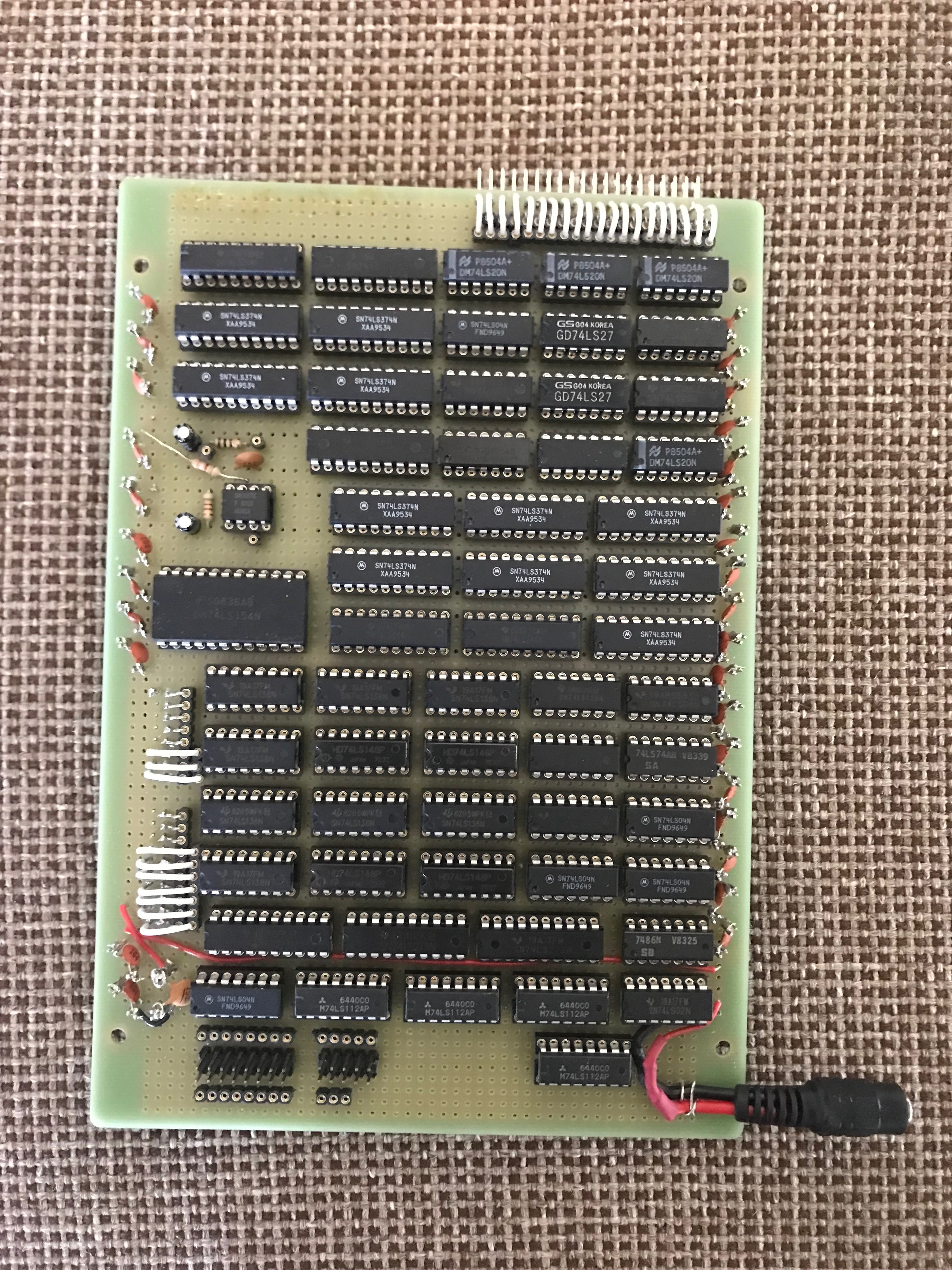
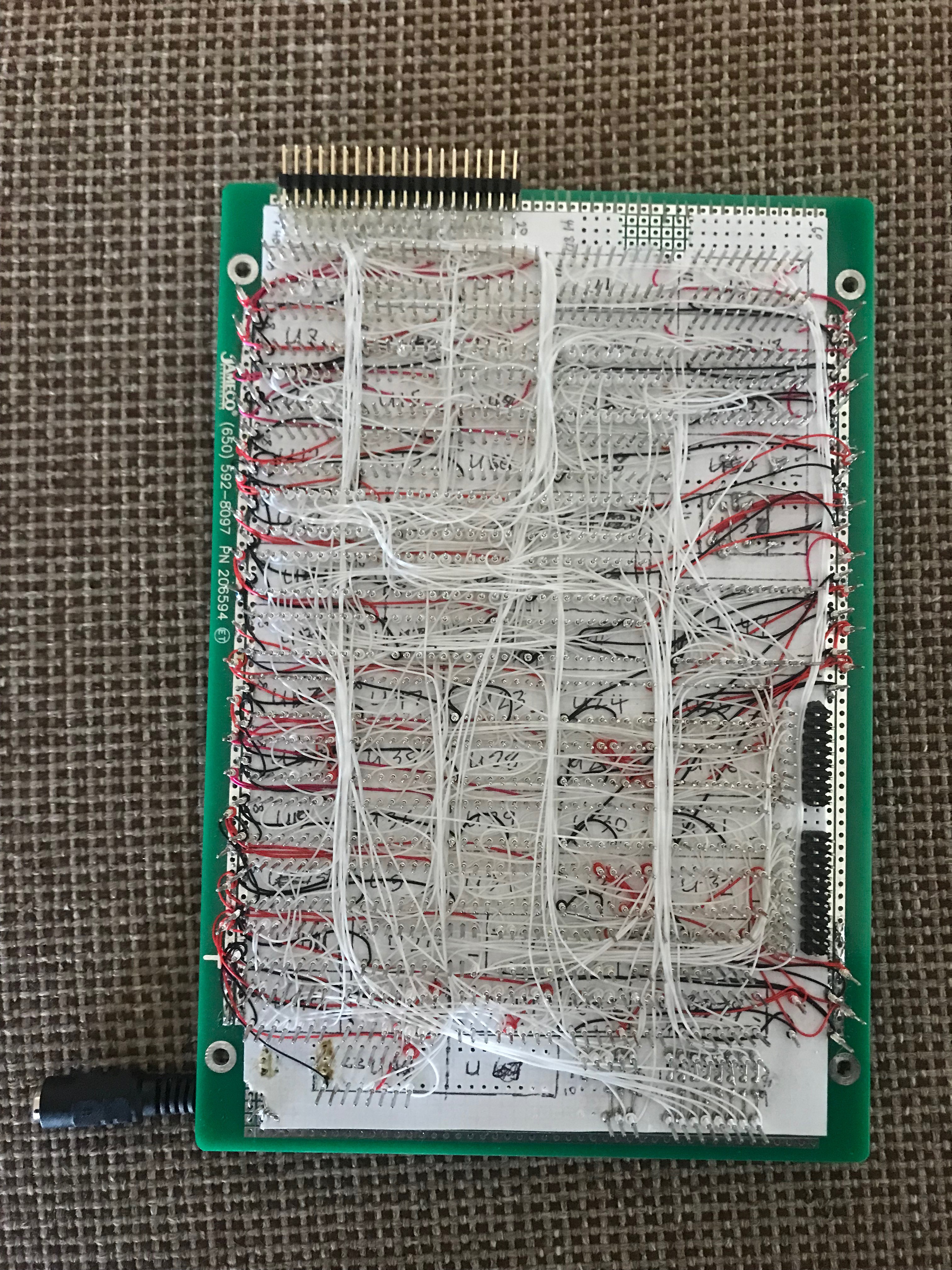
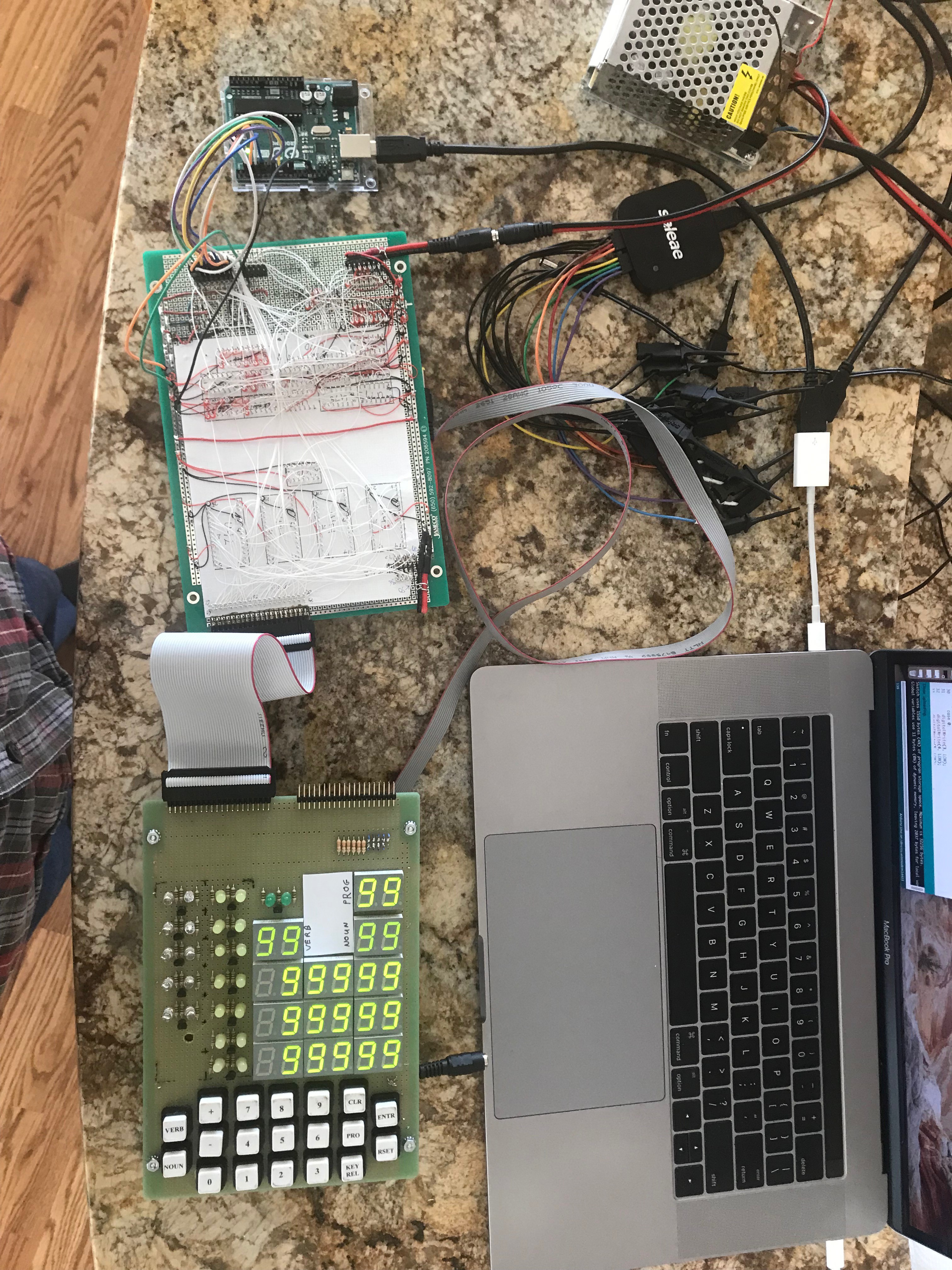
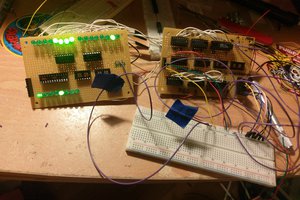
Why build a replica of the Apollo Guidance Computer? I have always wanted to build a computer based on TTL chips ever since that college lab course that taught the use of TTL chips. During my career as a software developer I was fortunate enough to work on a project that used a real time operating system where I was able to understand the intricacies of the operating system. I wrote device drivers for hardware boards that were created in house as well as the infrastructure add-ons. That was my favorite work project. Modern software developers have become so abstracted from the hardware and operating systems that their code is typically platform independent.
I want to understand a historic computer's architecture, both hardware and software, and what better computer than the Apollo Guidance Computer. The AGC has a serious coolness factor because it landed men on the moon and it was the first computer to use integrated circuit chips, thus bridging the gap between computers made from vacuum tubes and modern computers. The original Block I AGC was built using 4,700 single 3-input NOR gate chips. NASA pushed the manufacturers to improve the integrated circuit technology and reliability by creating the first flat pack chip. The Block II version of the AGC used these flat chips that contained two 3-input NOR gates. The Block II version was built from 2826 dual 3-input NOR gates (RTL chips) along with 3325 diodes and core memory. NOR gates were used because they are the “universal” gate from which all other logic gates can be derived. It was cheaper and quicker to throw all the time and money into developing one reliable chip at the cost of having to use more chips.
The AGC was designed and built by MIT in the early 1960s. The only small size computers of the time were developed to guide ballistic missiles. MIT was designing guidance control systems for the Polaris submarine launched missile. The Block I version of the AGC had 24K of ROM, 1K of RAM and 11 instructions. The Block II version had 36K of ROM, 2K of RAM and 34 instructions. Block II was based on the Block I architecture. Both were 16-bit computers with a clock speed of 1.024 MHz.
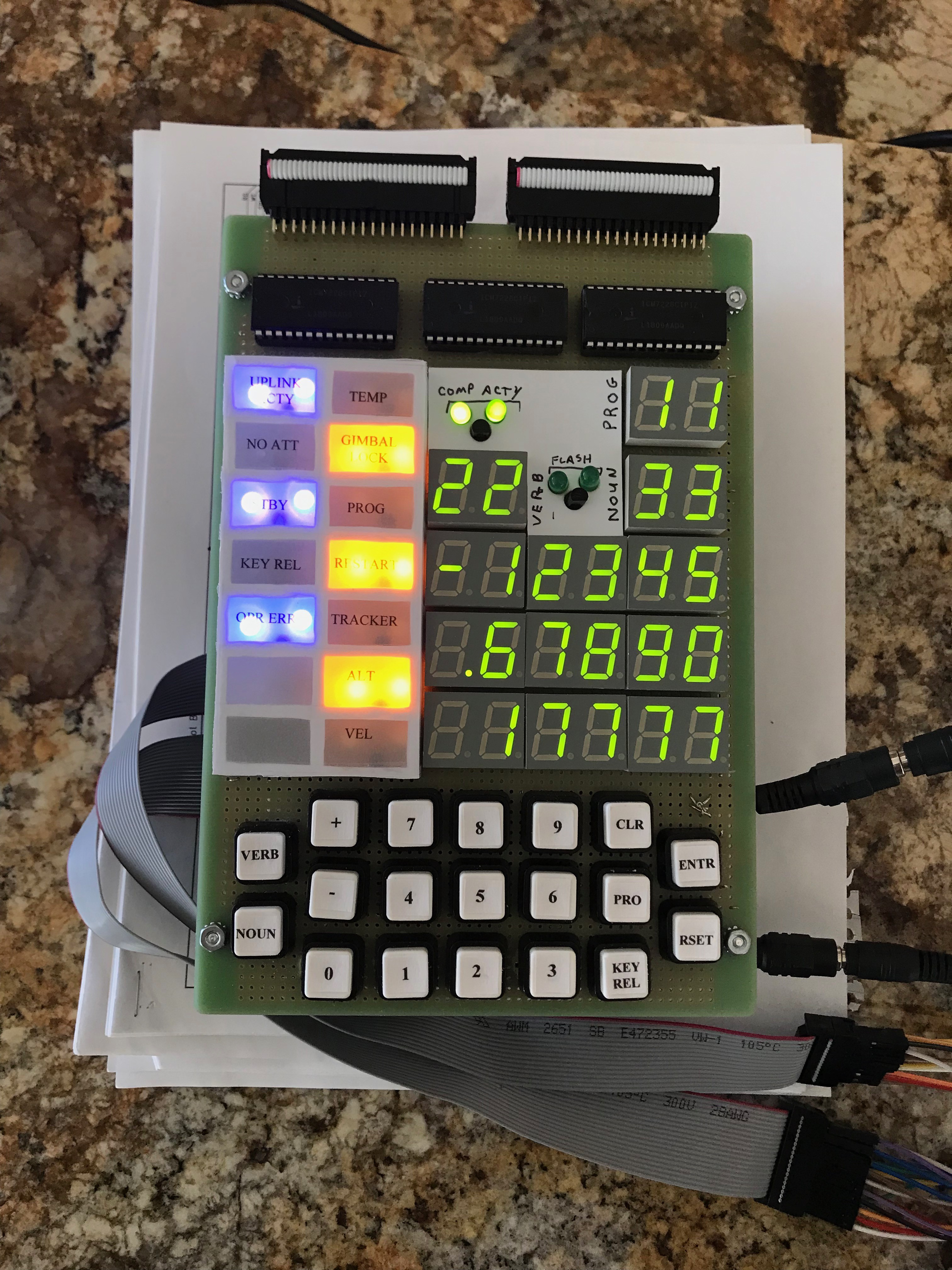
At the time there was no light weight, simplistic computer interface technology appropriate for a space capsule. The astronauts, who were test pilots, wanted gauges and dials as they would find in an airplane. The AGC used a simple keyboard and numeric displays. This calculator style interface was the first of its kind. The Block I version only supported the Command Module and flew the unmanned missions up through Apollo 6 where the Block II flew all the manned missions. The Block II upgrade was required as it also needed to fly the Lunar Module.
The AGC was designed using technology that did not exist at that time. By the end of the Apollo era, computer technology had progressed to the point that the AGC was obsolete. Manufacturers had gone on to produce the TTL series of chips that are still available today. As with most government contracts, there was not enough time or money to completely redesign the AGC with this newer technology.
The AGC solved two very difficult problems for aircraft that did not exist or were in their infancy, a digital autopilot and digital fly-by-wire. Autopilots of the time were analog devices that were large and heavy with limited capabilities. The X-15 project was just starting to introduce this technology. After the Apollo missions were complete in 1975, a surplus AGC was retrofitted into a F-8 Crusader fighter jet to be the first fly-by-wire aircraft. The other ground breaking feature was the incorporation of the newly developed Kalman filter algorithm. This was one of the first applications of the Kalman filter which is now ubiquitous in spacecraft and missile implementations.
Add on top of all that the fact that this computer and its software had to execute flawlessly, yet could not be fully tested ahead of time before actually landing on...
Read more »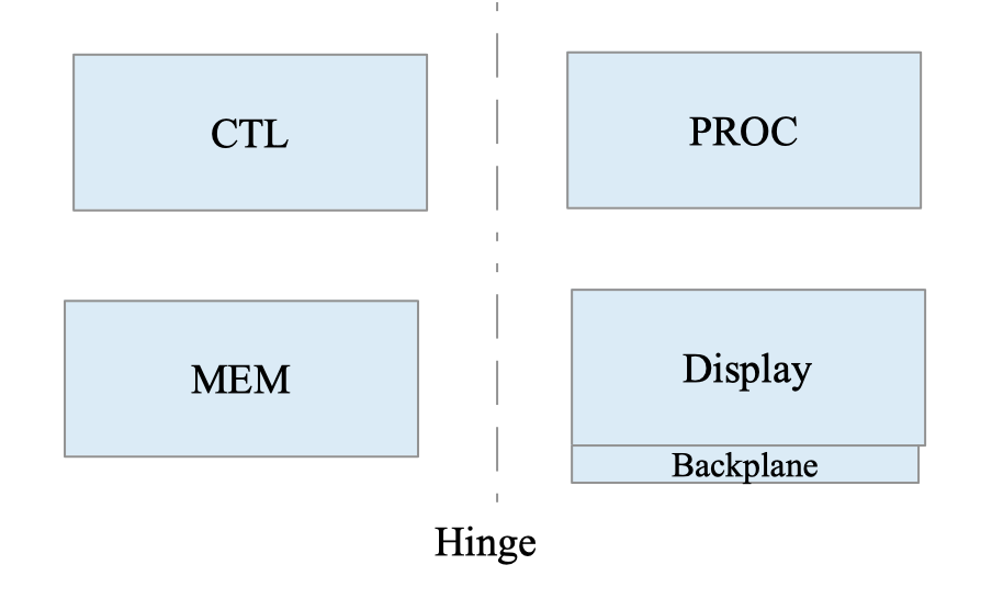


 Dave's Dev Lab
 Boxerbomb
 Pavel
Pavel
Fascinating and ambitious project, wishing you best of luck! I need to dig in more, but one question jumped out right away: what is the plan / approach to test the CPU? After all, the original only executed the actual moon landing mission code, which is probably available, but without right sensor inputs (or mocking their values in some way) its execution would not go far. Do you plan some test code, similar to what other CPUs have (I ran some on my Am9080 "implementation" in FPGA and it failed miserably, although monitor program ran without much problems, so I know that making a replica in any technology is hard).