1. Main feature
Figure 1 shows the external appearance of the PERSEUS-9. The enclosure is a die-cast aluminum case with external dimensions of 262 mm x 182 mm x 55 mm.
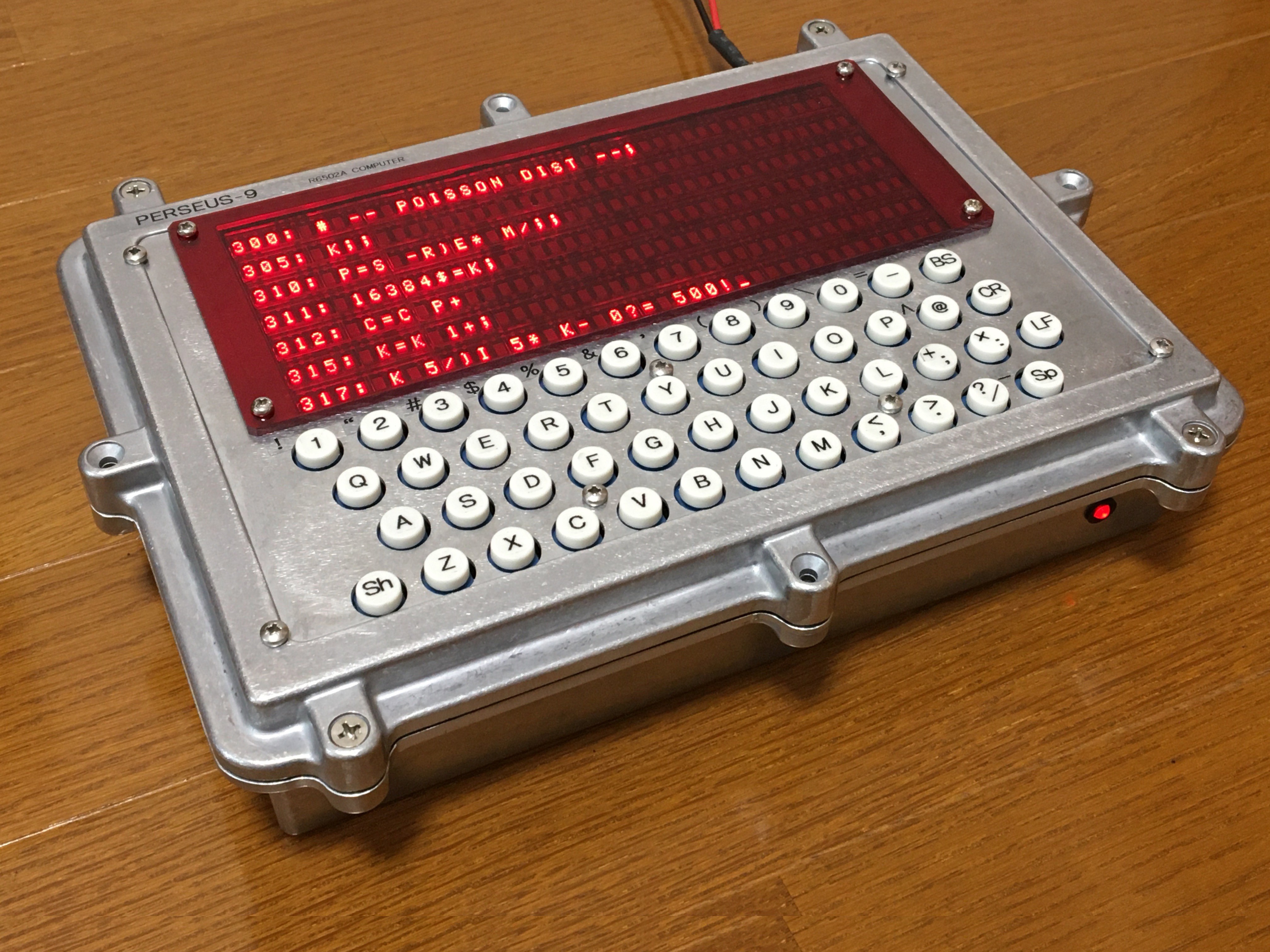
Fig.1 Appearance of PERSEUS-9
The user interface consists of a 48-key keyboard and a 40 x 7 LED character display. The display has been expanded from the 96-character display of the 6802 Serial Terminal to a 280-character display. Power is supplied externally via 5V, 3A power adapter. External Ni-MH 1.2V battery x 4 operation is also possible. User programs are backed up by the built-in battery.
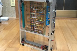
Figure 2 shows the inside of PERSEUS-9. The board has a two-tiered structure, and in this photo PB1, in which the main computer including the 1st CPU and the terminal part including the 2nd CPU are mounted, is visible. PB2, where the key switches and LED modules are mounted, is hidden underneath. The back of the enclosure has a power connecter, three D-sub connectors for the serial interface, and a 26-pin flat cable connector for the parallel interface. On the right side, the power switch, RUN/HALT switch, terminal select switch, and display reset switch are provided.
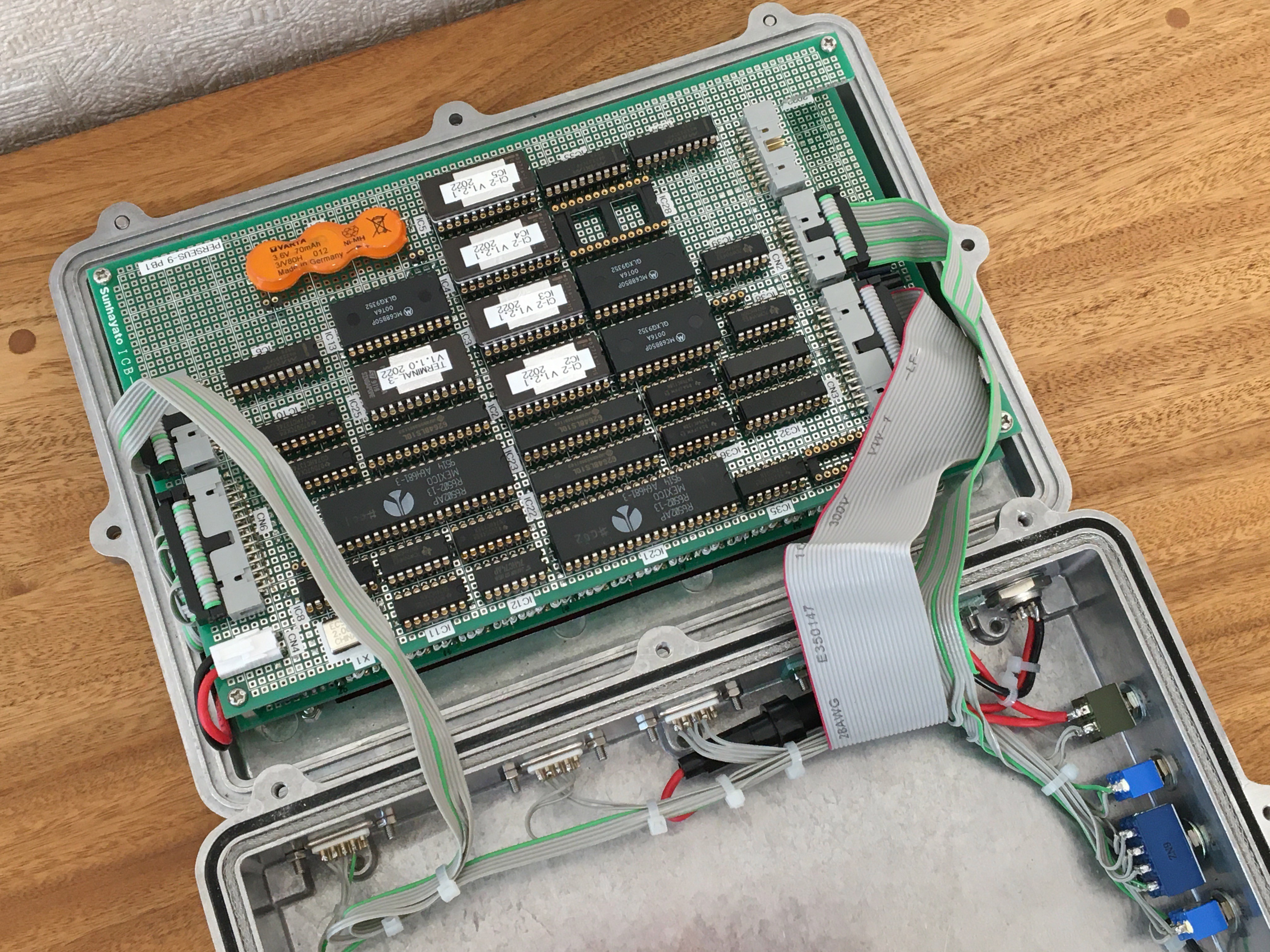
Fig. 2 Inside of PERSEUS-9
2. Enclosure
The enclosure is a die-cast aluminum case HQ-26-18-6N manufactured by Takachi of Japan, which is used. This enclosure is designed to be waterproof and dust-proof for outdoor equipment, but this function is ignored. Although the panel has many openings due to the hole drilling process, it maintains sufficient rigidity. Figure 3 shows the drilling of holes for switches in the panel using a reamer. 3mm-thick red transparent acrylic sheet is used as the filter for the LED display part.
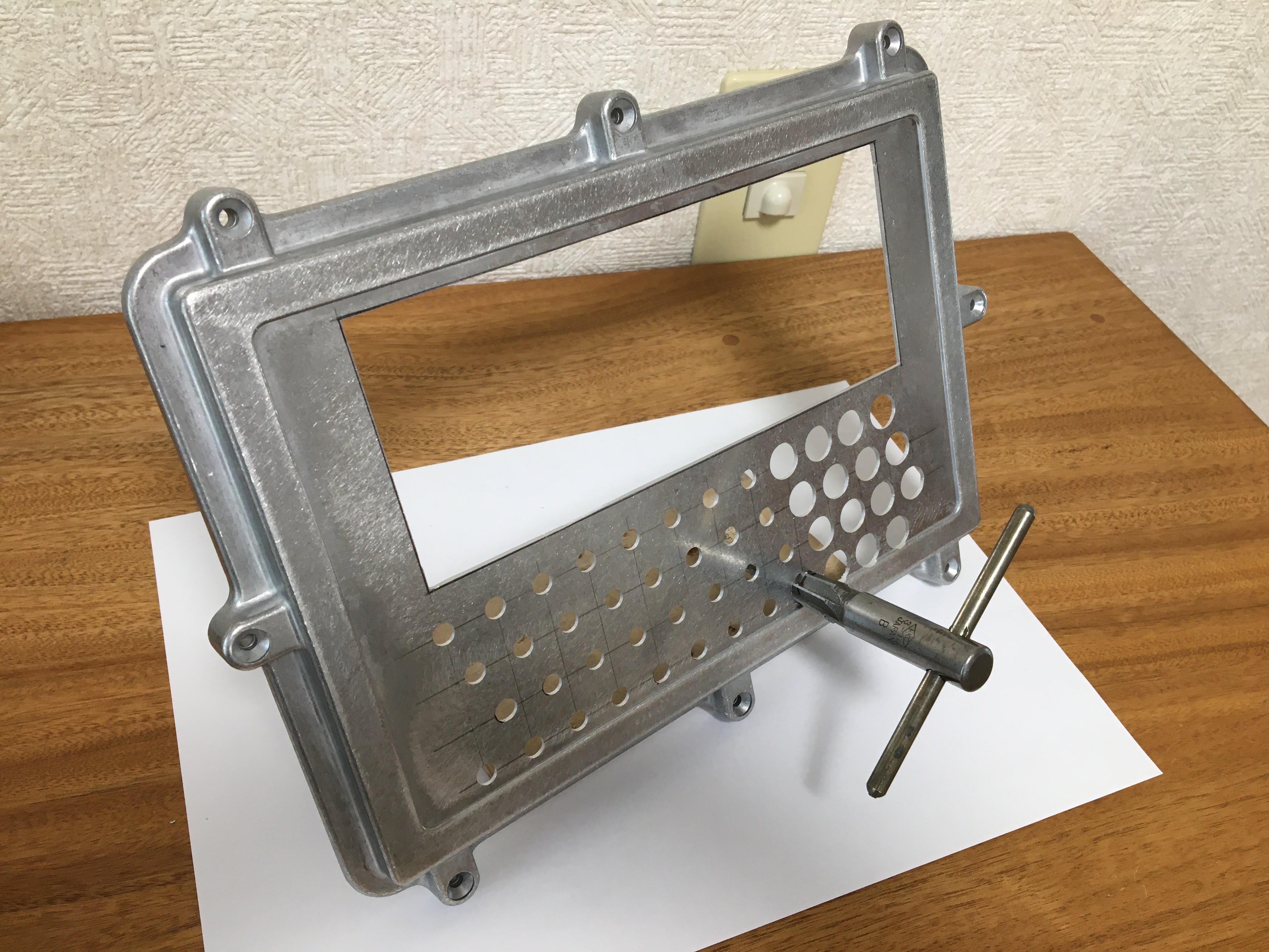
Fig. 3 Reaming work for enclosure
Figure 4 shows the connector holes for the interface and the holes for the toggle switches drilled in the back and sides. Such square holes are drilled continuously with a 3mm-diameter drill, the holes are pulled out, and then finished with a file.
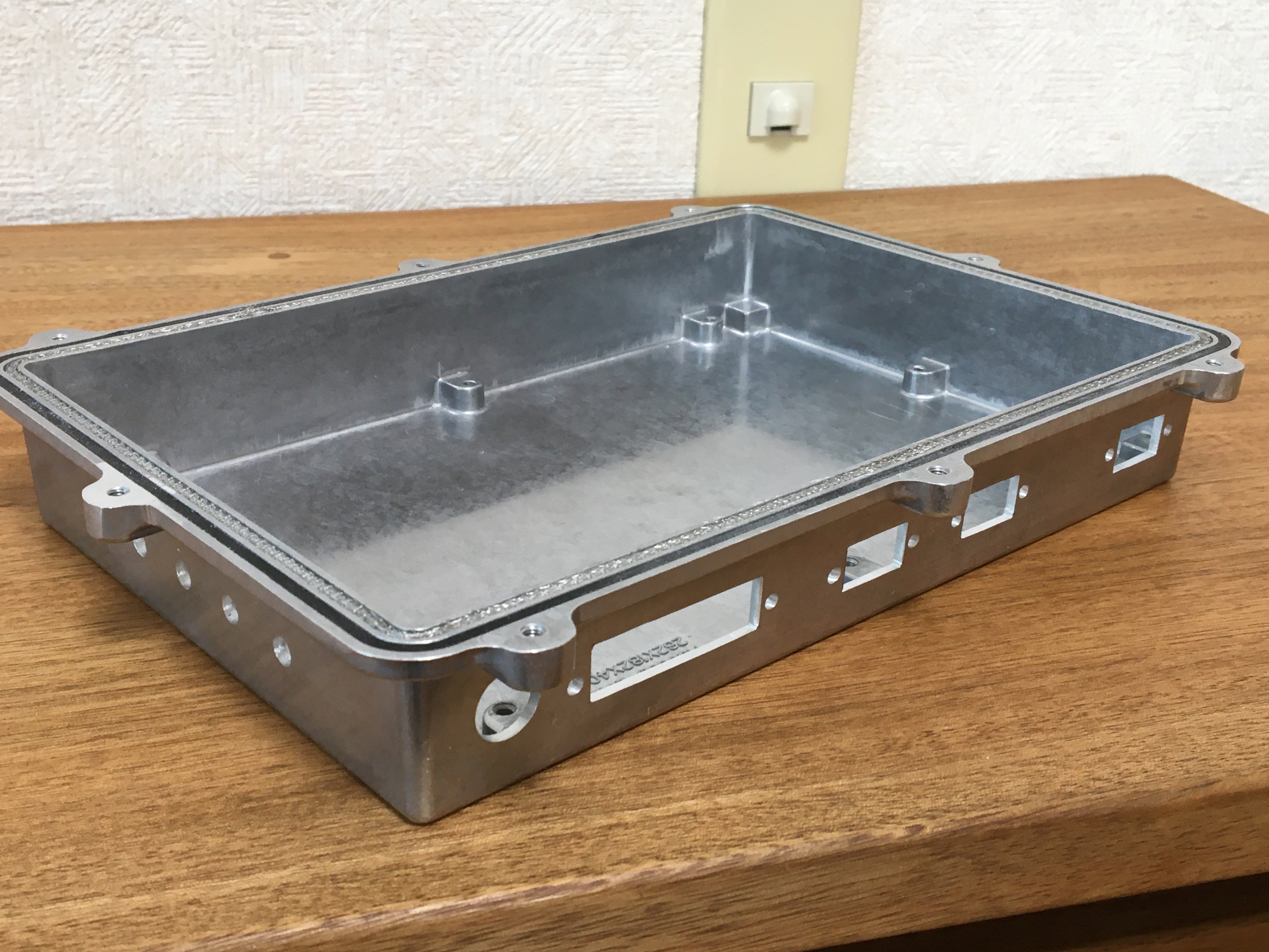
Fig. 4 Enclosure backside
3. Dual CPU hardware configuration
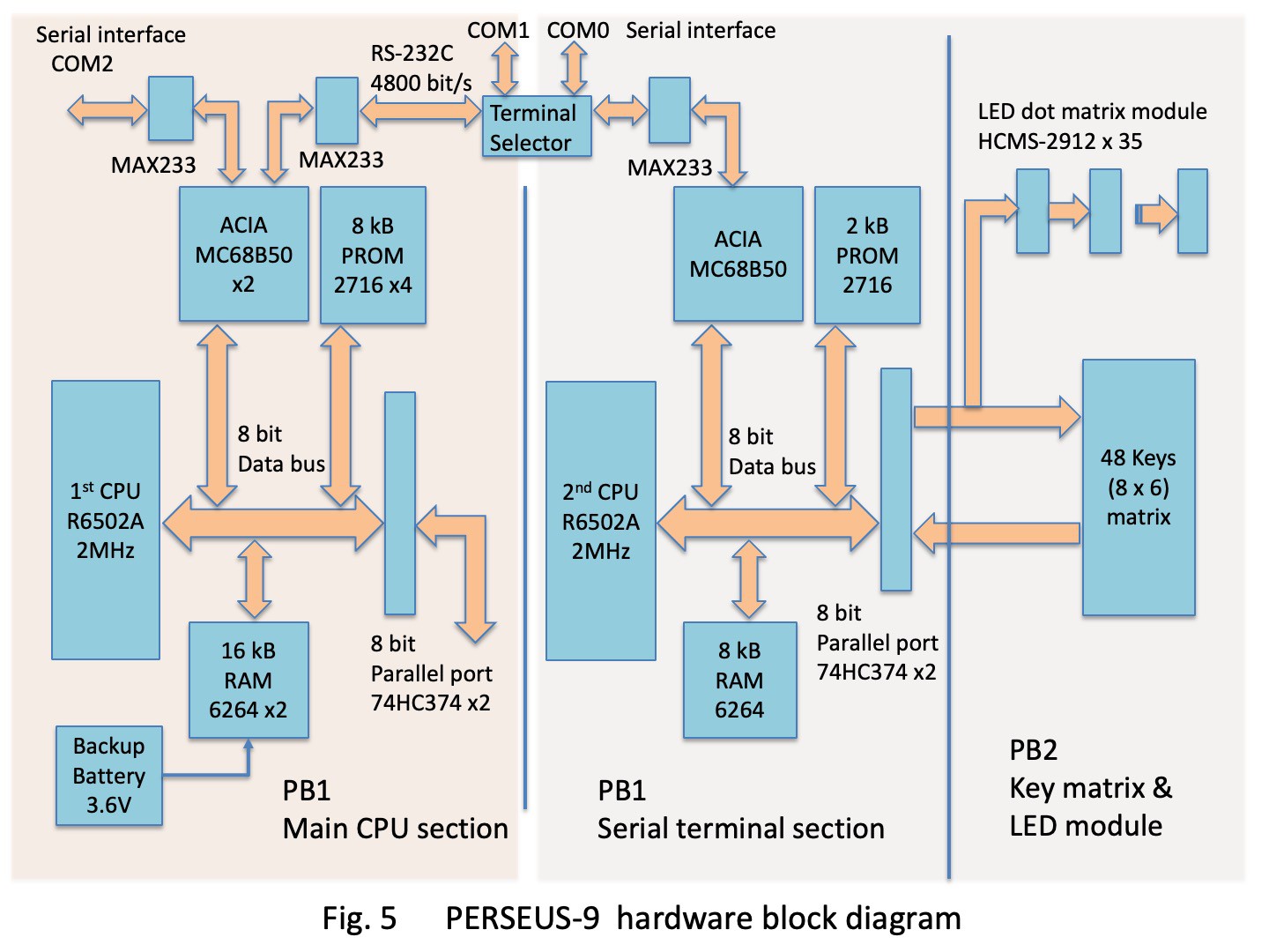
The hardware block diagram of PERSEUS-9 is shown in Fig. 5. The schematic and the parts location figure are shown in the attachment file. In Fig. 5, the left half of PB1 is the main CPU section shown on pages 1 to 3 of the schematic, and the 1st CPU is IC21. This is the almost same as removing the DMA control section which uses toggle switches and LEDs to input addresses and data from the PERSEUS-8 circuit. The main CPU section implements and executes homemade floating point interpreter CI-2 in 8 kB PROM area. The 16 kB RAM space is the user program storage area for the interpreter and the system work area.
The right half of PB1 in Fig. 5 is the serial terminal section including the 2nd CPU shown on page 4 of the schematic. The 2nd CPU runs the serial terminal system software CT-3 on a 2kB PROM. This is basically similar to the 6802 Serial Terminal, but PERSEUS-9 has 2.9 times more LED modules than the 6802 Serial Terminal, so the processing speed needed to be faster. Therefore, the MC6802 (1 MHz) CPU was replaced with a 6502A (2 MHz). This resulted in a 6502 (2 MHz) dual-CPU configuration for the entire PERSEUS-9. This is not a recent CPU configuration with many cores, but it is a configuration with a main CPU and an I/O CPU, which was common around 1980. The two computer parts have the same address mapping to facilitate hardware operation verification. For example, the ROM and flat cable of the terminal part can be replaced with the main part to verify the operation as a terminal.
4. Peripheral devices
In Fig. 5, PB2 consists of 48 key switch matrices and 35 5x7 dot 8-character LED modules (HCMS-2912) shown on page 6 and page 5 of the schematic. The data lines of the LED modules are connected in cascade. And all of these are connected to the 8-bit...
Read more » Mitsuru Yamada


 Keith
Keith
 jaromir.sukuba
I love the binary voltage display LEDs on the AD converter! This project is marvelous!