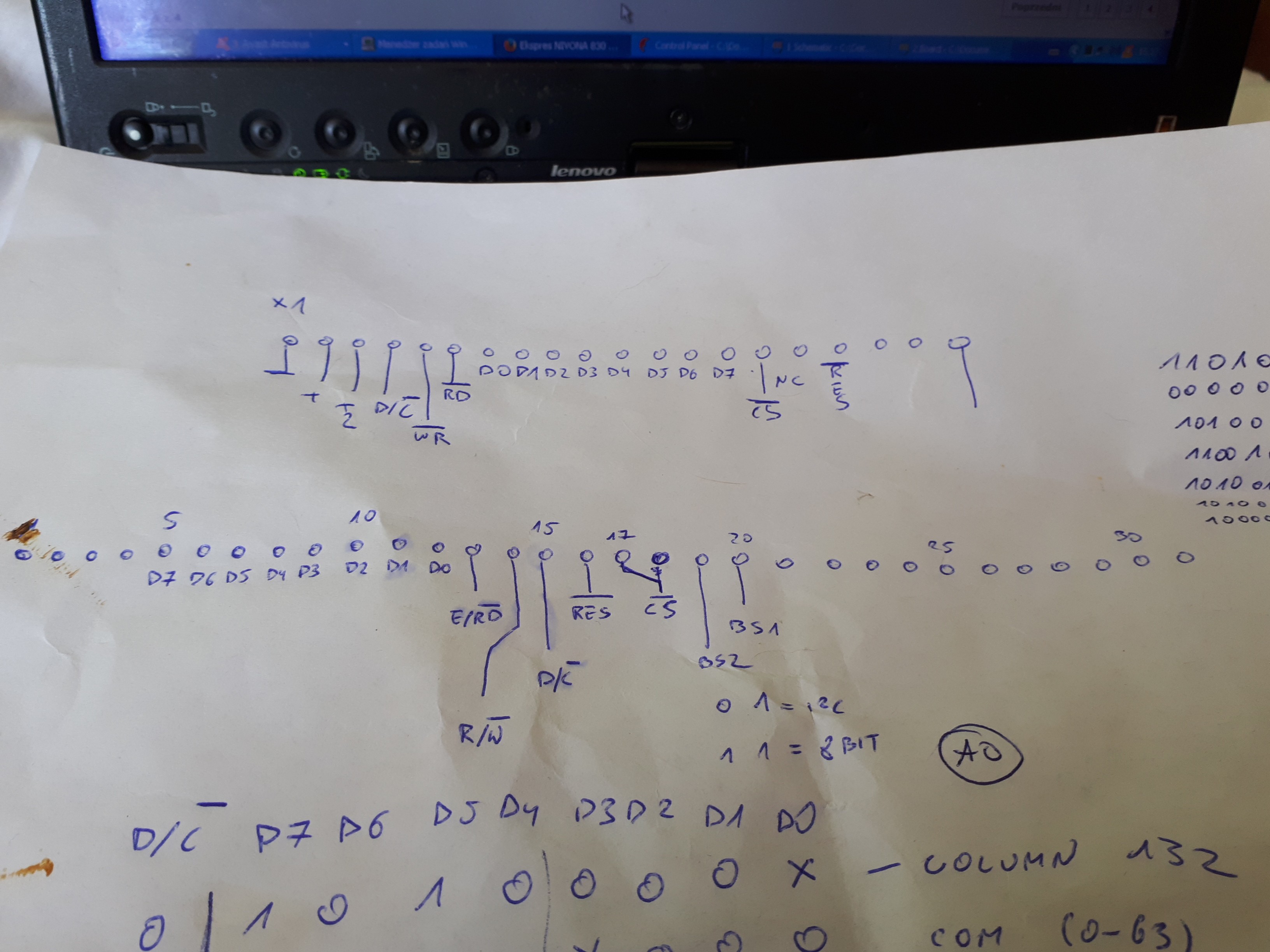
When in 2019 I try to order replace display for my machine - SSD1303T10, the last piece are gone. Someone have few on ebay on directly from china, but I need instant fix and waiting few weeks for shipping are not acceptable. But quick searching and Yes, similar OLED display sold as Ardruino compatible SPI display. I order one and using documentation make pinout map:
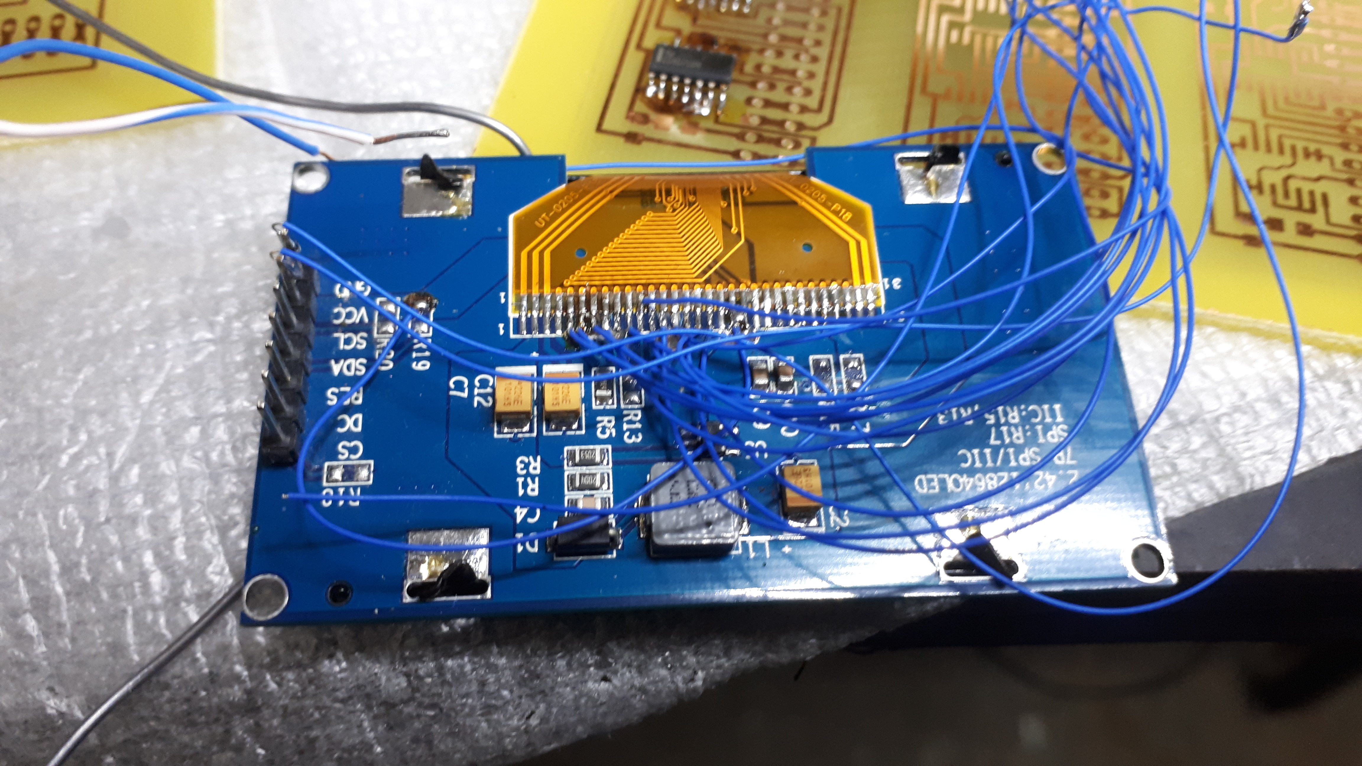
Using lots of wires I try to connect new display parallel to old, but first I must de-solder display connector because any not used in SPI communication pins are grounded on PCB.
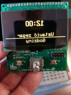
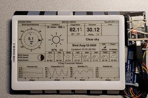
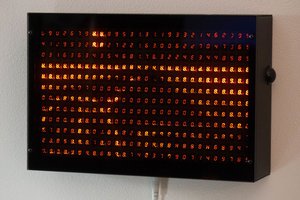
Finally I have see image but horizontal mirrored:
In this moment I start to read documentation for new controller and found command responsible for horizontal "scan direction". I think, if I use "man in the middle" attack and put some additional device on bus, I can send this command and reverse the screen. Searching for any uP test board, I found another idea. If Nivona panel CPU send this command, we can modify only one bit and maybe we don't need any uP for this. I'm not a extremist using only vacuum tube or single transistors, but using CPU for led blinking if we can use NE555?
Using my old Tektronix logic analyser, I found that any full screen data package are
preceded by this byte.
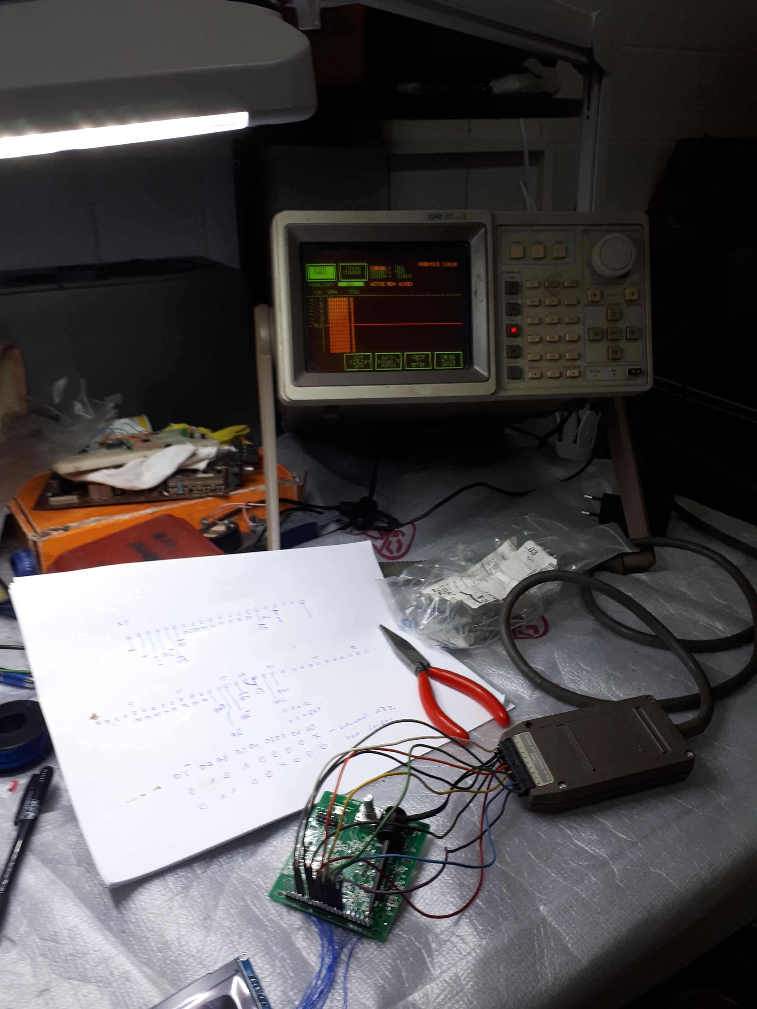
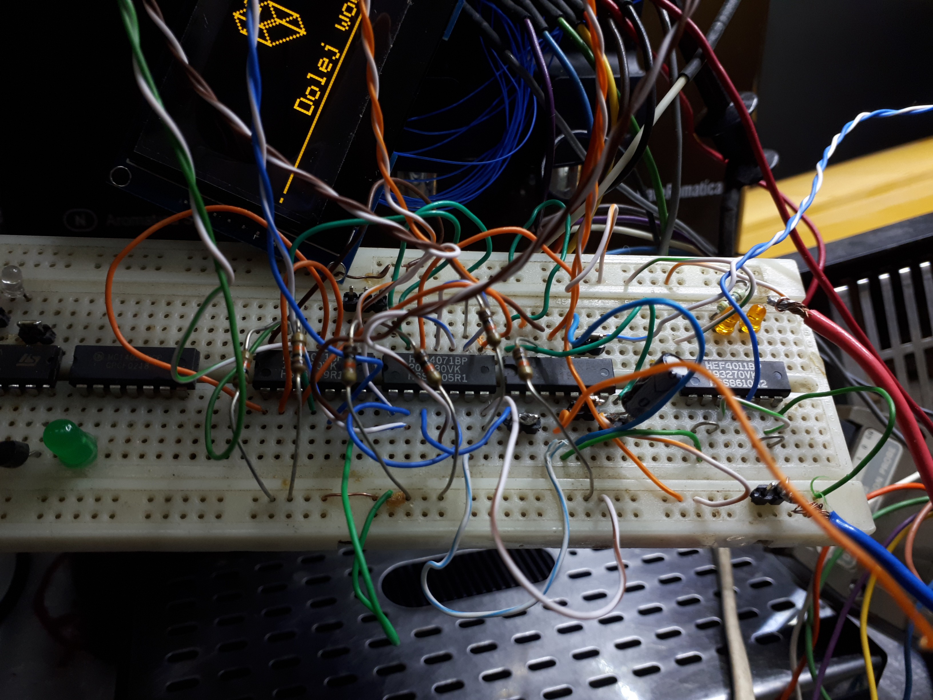
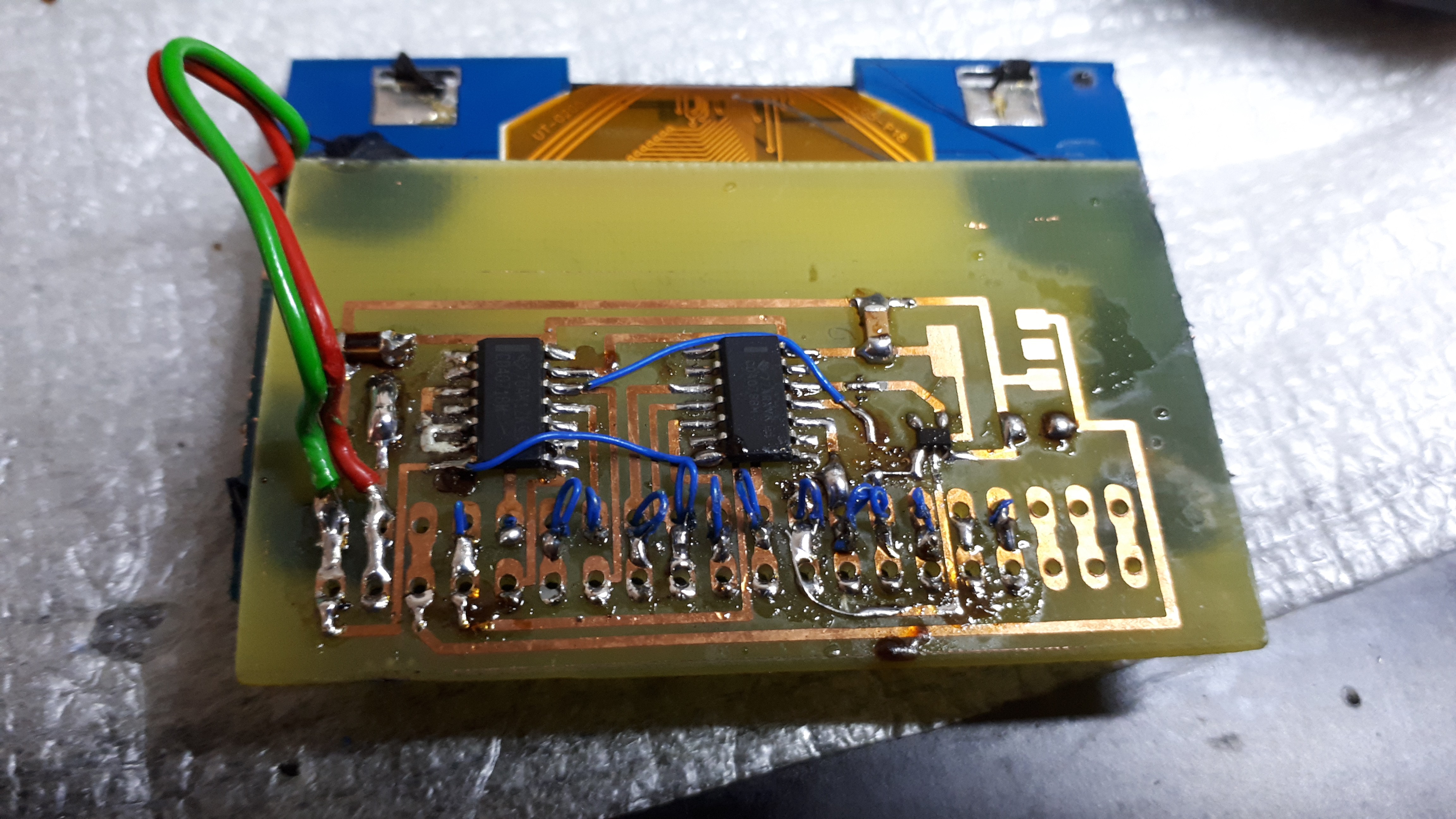
Using only 40xx logic chip I try to make circuit changing one bit in data stream, but mounted on breadboard circuit don't change anything on screen.
After few hours of changing chips, logic levels and supply voltages, time domain logic analyse show nature of problem.
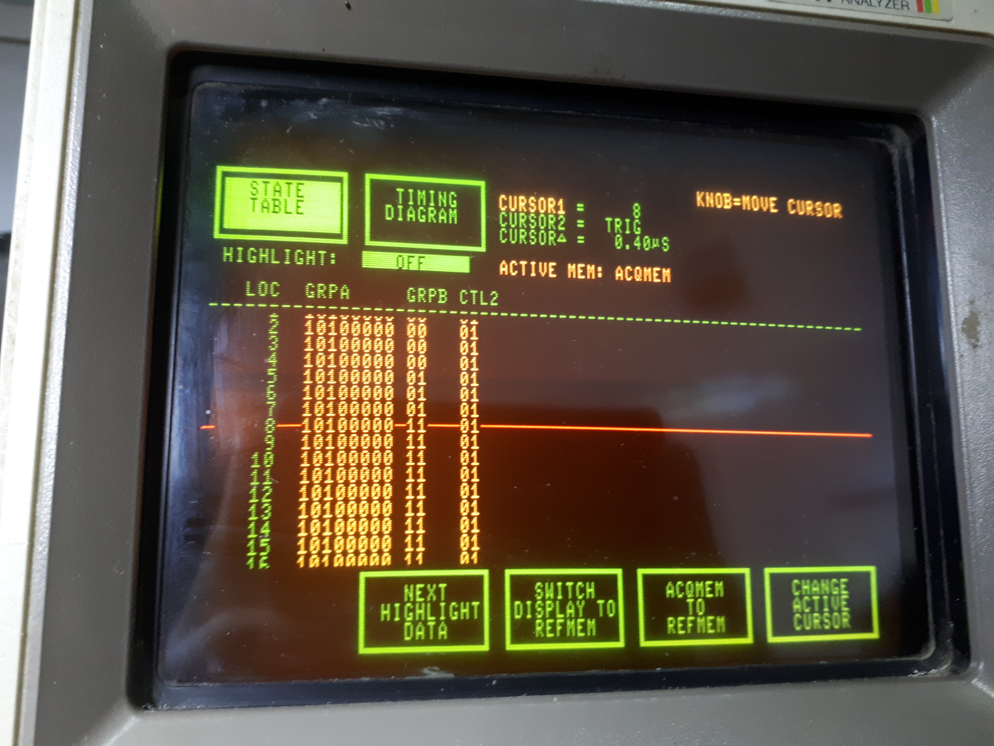
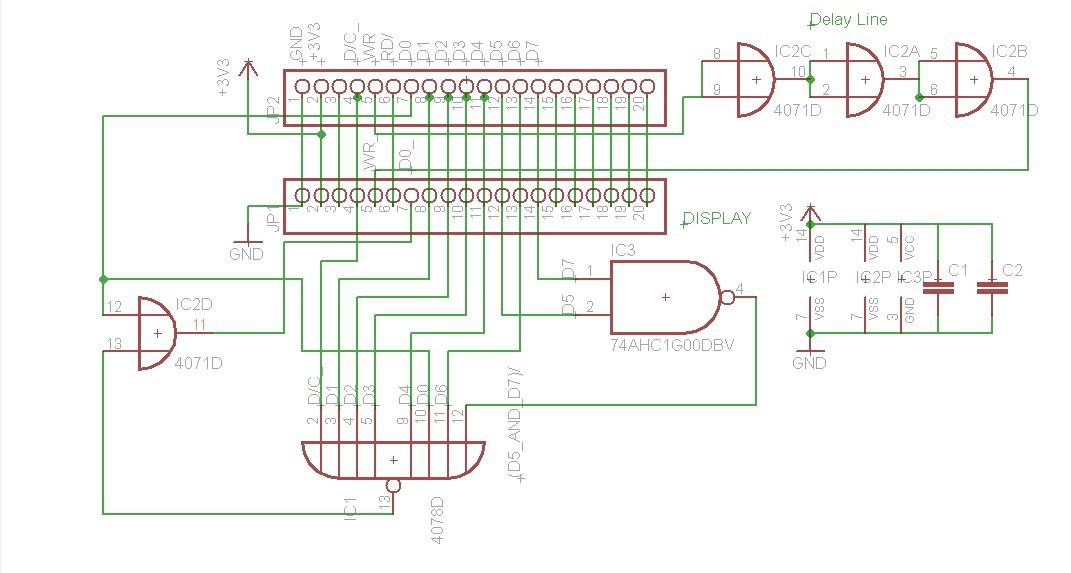
Time of propagation - 400ns, state change come to display control IC too late, after rising edge of writing pulse. Simple delay line make of not used gate solve problem.
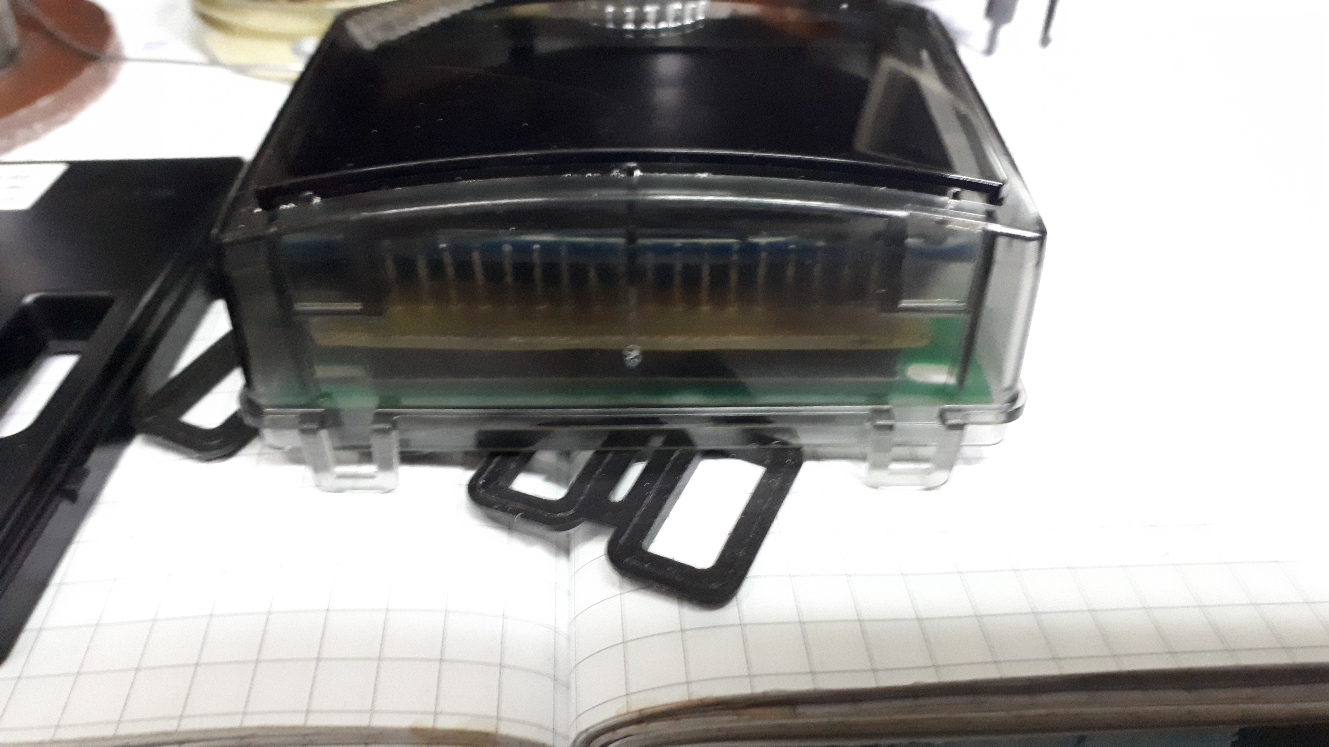
First home made PCB, some bug fixing wires and after removing parts of plastic from panel I can put it together.
Finally forum user amigos from elektroda.pl motivate me to make better board project - not a add in module but full replacement including DC-DC converter.
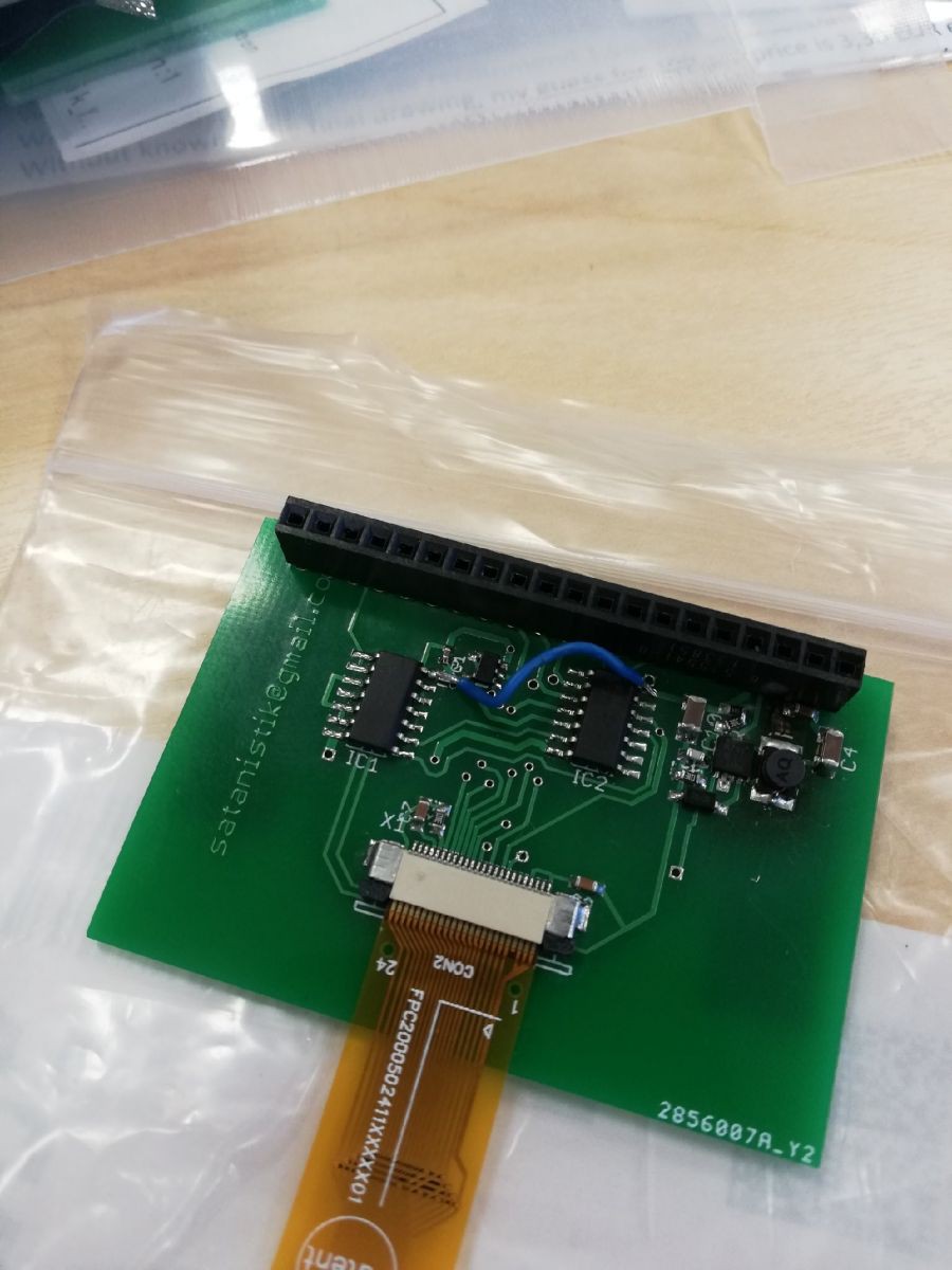
The extra bonus is we can use this not only for coffee machine but in Agilent U1273A multimeter and some industrial machine. I think this hack help save hundreds of gadgets - repairs are the best recycling ;-).
Sory for my English, I preferred scrap yards to school.

 Chris Combs