Guillermo Perez Guillen
-
3. LoRaWAN System Range Testing
07/26/2022 at 19:11 • 0 commentsThe received signal strength indicator (RSSI) is a reference scale (in relation to 1 mW) to measure the power level of the signals received by a device in wireless networks (typically WIFI or mobile telephony).
The scale tends to the value 0 (zero) as the center; y represents 0 RSSI or 0 dBm. Although theoretically it can be the case of measuring positive values, generally the scale is expressed within negative values; the more negative, the greater the loss of signal. On this scale a level of 0 dBm is equal to 1 mW (milliwatt).
RSSI indicates received strength, not signal quality; since the latter is determined by contrasting the intensity of the signal with respect to the signal-to-noise ratio.
Below you can see a table that can serve as a reference for the signal intensity.
Signal strength (dBm) Qualifier Appropriate uses -30 Excellent This is the maximum achievable signal strength and will be appropriate for any usage situation -50 Excellent This excellent signal level is suitable for all network uses -65 Very good Recommended for smartphones and tablets -67 Very good This signal strength will be sufficient for voice over IP and video streaming -70 Acceptable This level is the minimum signal strength required to ensure reliable package delivery and will allow you to browse the web and exchange emails -80 Bad Allows basic connectivity, but packet delivery is unreliable -90 Very bad A noise that inhibits most functions -100 Worst Total noise LINK TESTS WITH THREE TYPES OF ANTENNAS
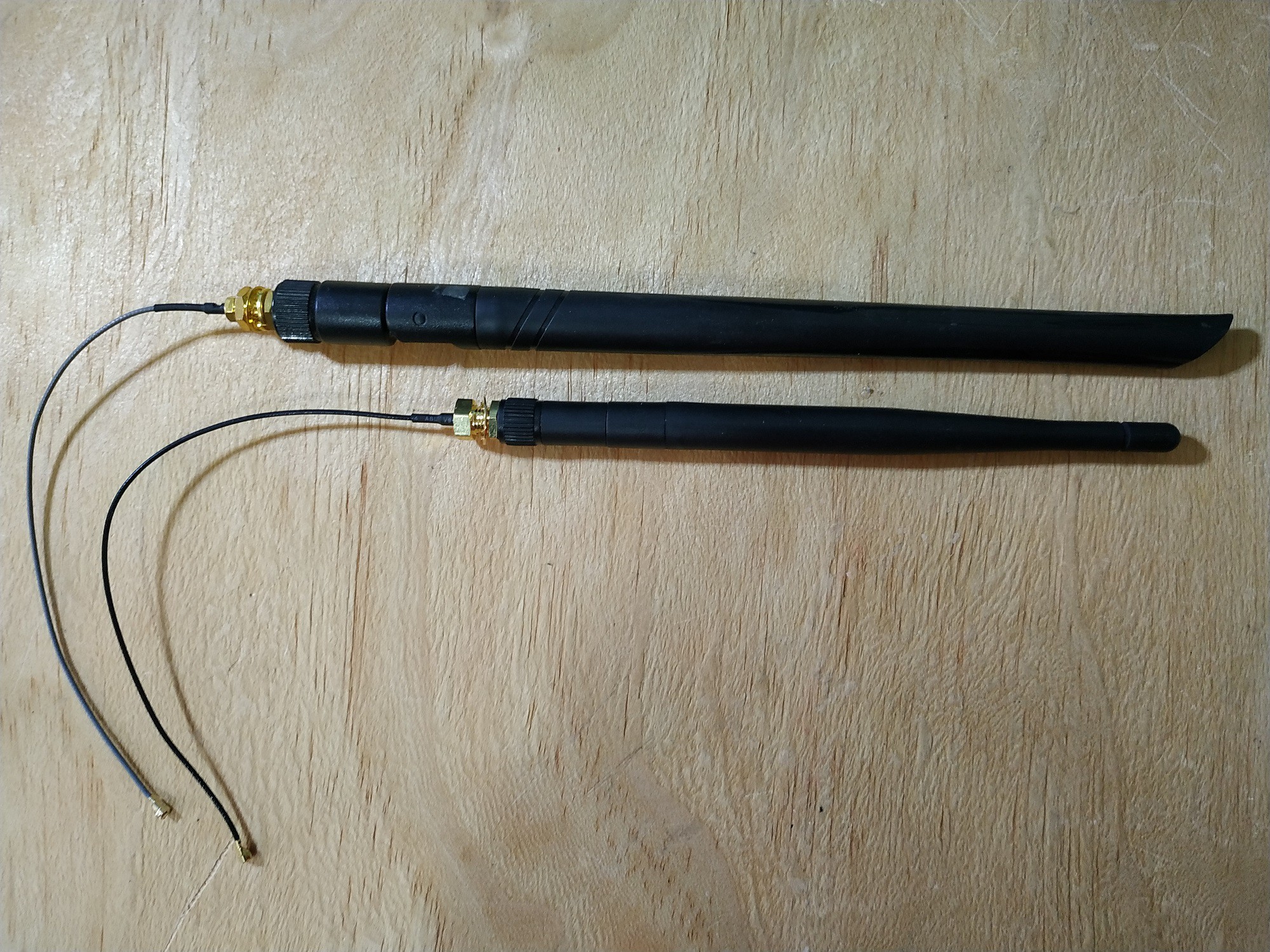
- Here I have used the schematic diagram from post # 4 and I made 50 meters test links to test three different types of antennas.. Below I show you two antennas used in WiFi devices.
![]()
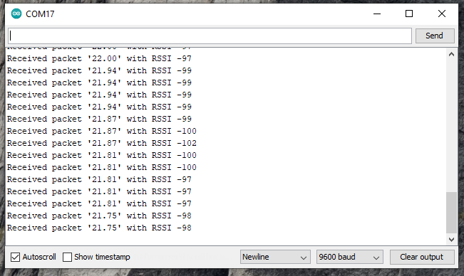
The quality of the signal is bad according to our table, in the image below we see reception signals between -97 and -102 dBm.
![]()
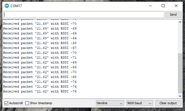
- Later we tested two antennas of a pole and of application in programming boards in GSM telephony.
![]()
The signal improved remarkably between -64 and -76 dBm, I only observe some instability in maintaining the signal as it goes up and down continuously.
![]()
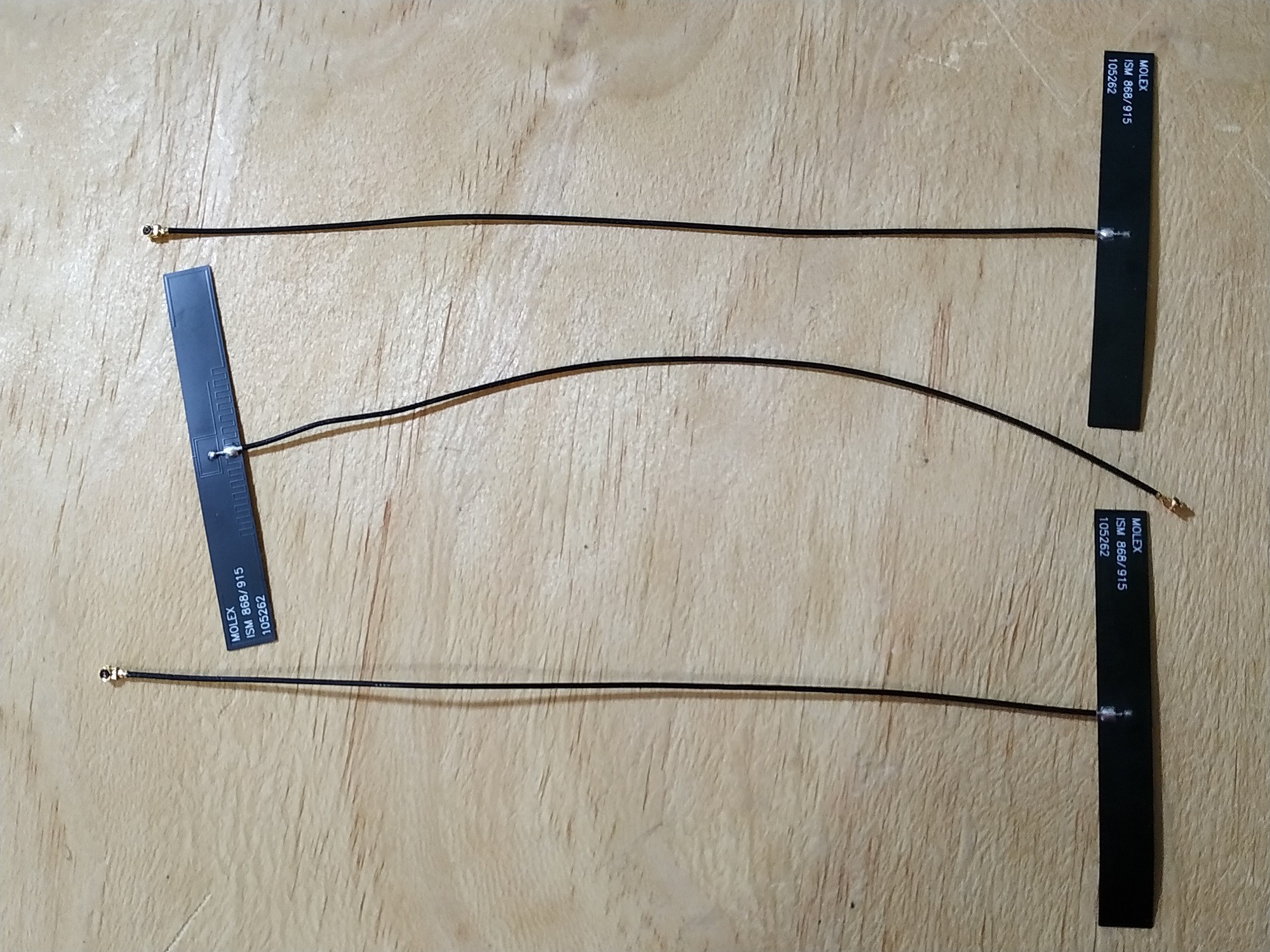
- Finally, I have tested the original dipole antennas shown in the image below.
![]()
The signal is good and stable, staying between -64 and -69 dBm for a long time.
![]()
Honestly, sending a message between two nodes in short links can feel like a real accomplishment. But the industry-wide excitement around LoRa is anchored in its long-range communication capabilities.
LONG LINK TEST
- I left the transmitter in the same room and headed out walking to the ecological reserve with the receiver to see if the distance affected the range signal. Through some obstructions, transmission faded out at around 300 meters. The verdict? Definitely better than Wi-Fi, but not morethan 350 meters where the street curved into an area where there was no longer a clear line-of-sight, transmission quickly stopped.
- In my case, this system works for me since the shortest point of the ecological reserve is 50 meters from my house, and the longest point is approximately 500 meters. So I can choose some strategic points to monitor the ecological reserve without problems.
-
2. Communication Between Two MKR WAN 1300
07/26/2022 at 18:43 • 0 commentsLoRaWAN allows devices to communicate over tens or even hundreds of kilometers, all without a cell network or a high-powered antenna array. The disadvantage with this technology is that data rates become severely restricted—in the low kb/s range depending on conditions. While you might not be able to stream a 4k movie or even a low-fi audio clip, LoRaWAN is an excellent option for intermittent sensor data spread over a wide geographic area.
Can you set up point-to-point communication between two MKR WAN boards as the first step towards LoRaWAN exploration?
The good news is that point-to-point communication is easy, though figuring out the steps can be tricky. Let’s walk through how to get one-way communication going between two of these boards.
Monitoring Temperature Using Two MKR WAN 1300
Once you have your hardware ready to go, follow these steps to install and run your Arduino LoRaWAN:
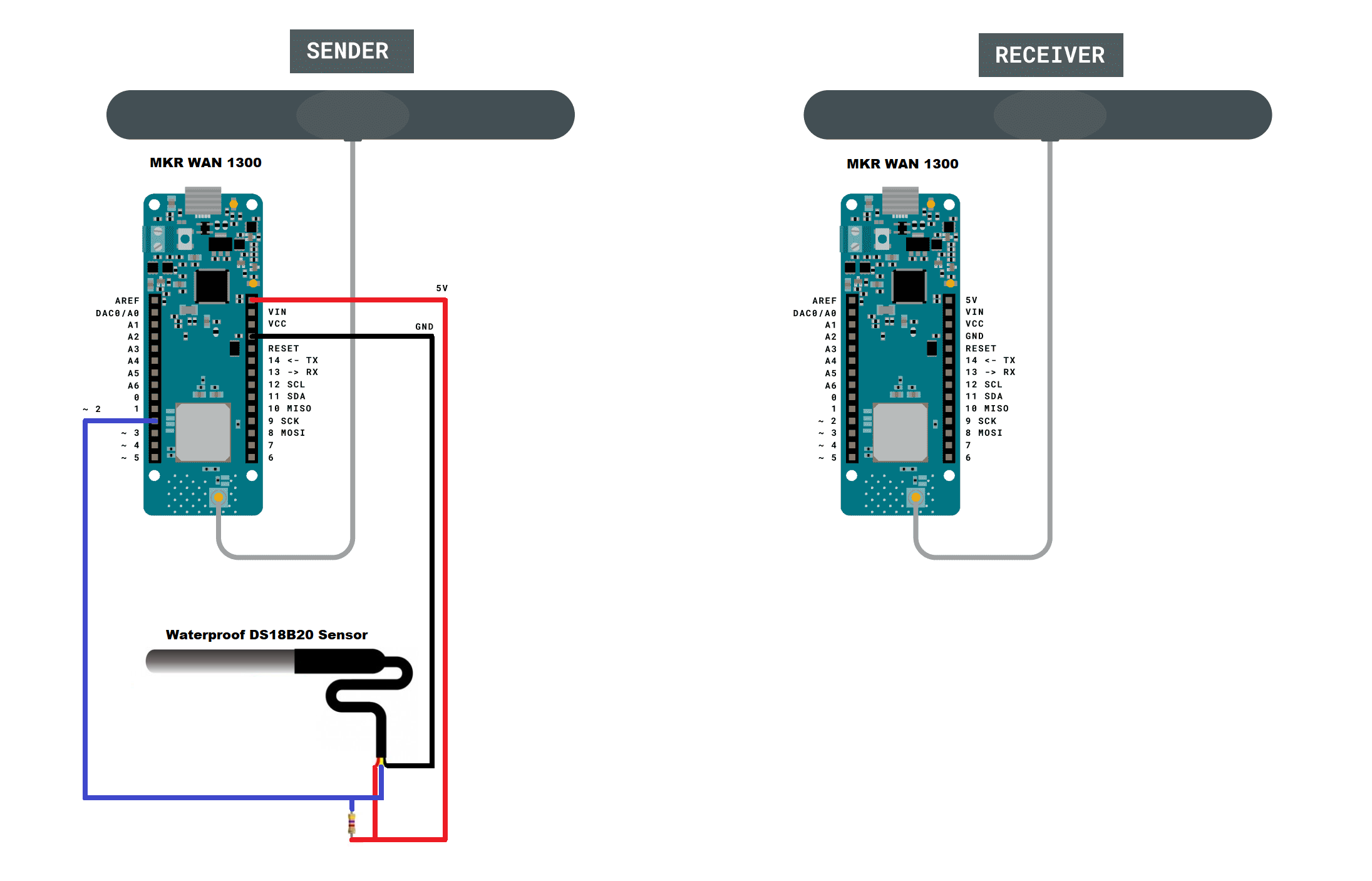
- Physically attach an antenna to both MKR WAN boards and make de connections as shown below in schematic diagram.
![]()
Open two instances of the Arduino IDE via a desktop or Start menu shortcut. Opening both separately allows you to manipulate two serial ports at the same time. Doing so will make the process much easier.
Navigate back to File-Examples, then LoRa. Under this section, load “LoRaSender” onto one board, then “LoRaReceiver” to the other.
In my case I modified these codes to monitor the temperature and using the "Waterproof DS18B20 Sensor" that came in the element14 gift kit.
The two libraries of the DS18B20 temperature sensor used you can download here: 1) Arduino-Temperature-Control-Library and 2) OneWire-Library
The sketch "LoRaSender_v1.ino" is shown below:
// AUTHOR: GUILLERMO PEREZ GUILLEN

#include <SPI.h>
#include <LoRa.h>
#include <OneWire.h>
#include <DallasTemperature.h>

// Data wire is plugged into port 2 on the Arduino
#define ONE_WIRE_BUS 2
// Setup a oneWire instance to communicate with any OneWire devices (not just Maxim/Dallas temperature ICs)
OneWire oneWire(ONE_WIRE_BUS);
// Pass our oneWire reference to Dallas Temperature.
DallasTemperature sensors(&oneWire);

int counter = 0;

void setup() {
  Serial.begin(9600);
  while (!Serial);
  Serial.println("LoRa Sender");
  if (!LoRa.begin(915E6)) {
    Serial.println("Starting LoRa failed!");
    while (1);
  }
  sensors.begin();
}

void loop() {
  sensors.requestTemperatures();   //The command to read the temperature is sent
  float temp= sensors.getTempCByIndex(0); //The temperature is obtained in ยบC
  Serial.print("Sending packet: ");
  Serial.println(counter);
  // send packet
  LoRa.beginPacket();
  LoRa.print(counter);
  LoRa.print(".- Temp = ");
  LoRa.print(temp);
  LoRa.print(" C");
  LoRa.endPacket();
  counter++;
  delay(4000);
}
The sketch "LoRaReceiver_v1.ino" is shown below:
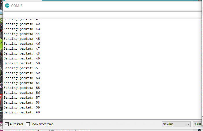
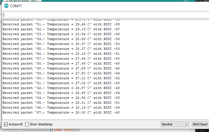
// AUTHOR: GUILLERMO PEREZ GUILLEN #include <SPI.h> #include <LoRa.h> void setup() { pinMode(LED_BUILTIN, OUTPUT); Serial.begin(9600); Serial.println("LoRa Receiver"); if (!LoRa.begin(915E6)) { Serial.println("Starting LoRa failed!"); while (1); } } void loop() { // try to parse packet int packetSize = LoRa.parsePacket(); if (packetSize) { // received a packet Serial.print("Received packet '"); // read packet while (LoRa.available()) { Serial.print((char)LoRa.read()); } // print RSSI of packet Serial.print("' with RSSI "); Serial.println(LoRa.packetRssi()); digitalWrite(LED_BUILTIN, HIGH); delay(2000); digitalWrite(LED_BUILTIN, LOW); } }- Start a serial monitor on both ports, and you’ll see the transmitter board sending a packet every four seconds. The receiver serial port—if everything works properly—will show it receiving these the packet with the sensor's temperature and a Received Signal Strength Indication (RSSI) number to show how well the pair is communicating.
Below you can see an image of the data submission:
![]()
Below you can see an image of the data reception:
![]()
-
1. Getting Started
07/26/2022 at 18:40 • 0 commentsMKR WAN 1300
Features:
- MKR WAN 1300 is a powerful board, and Its the ideal solution for makers wanting to design IoT projects with minimal previous experience in networking having a low power device.
- The Arduino MKR WAN 1300 includes Lora connectivity that can perform very long-range transmission operations consuming low power. The MKR WAN 1300 is incorporated with the Microchip® SAMD21 which is a low-power processor.
- A range of technologies available for the communication between IoT devices including WiFi and Bluetooth. But there is one major problem with these technologies – they consume a lot of power.
- The operating voltage of the circuit is 3.3V while the voltage through Vin and USB is 5V.
- There are total 8 digital I/O pins incorporated on the board while the number of analog pins is 7. And the pins that can be used for the PWM motor control are 12.
- The board controller comes with a flash memory of 256KB while the SRAM memory is 32KB. While the SRAM memory is reserved to generate and manipulate variables when it runs.
- Interface this MKR board with Arduino IoT cloud that guarantees safe communication between all connected devices.
- The carrier frequency of this board is 433/868/915 MHz which is termed as the frequency of a carrier wave, calculated in cycles per second, or Hertz.
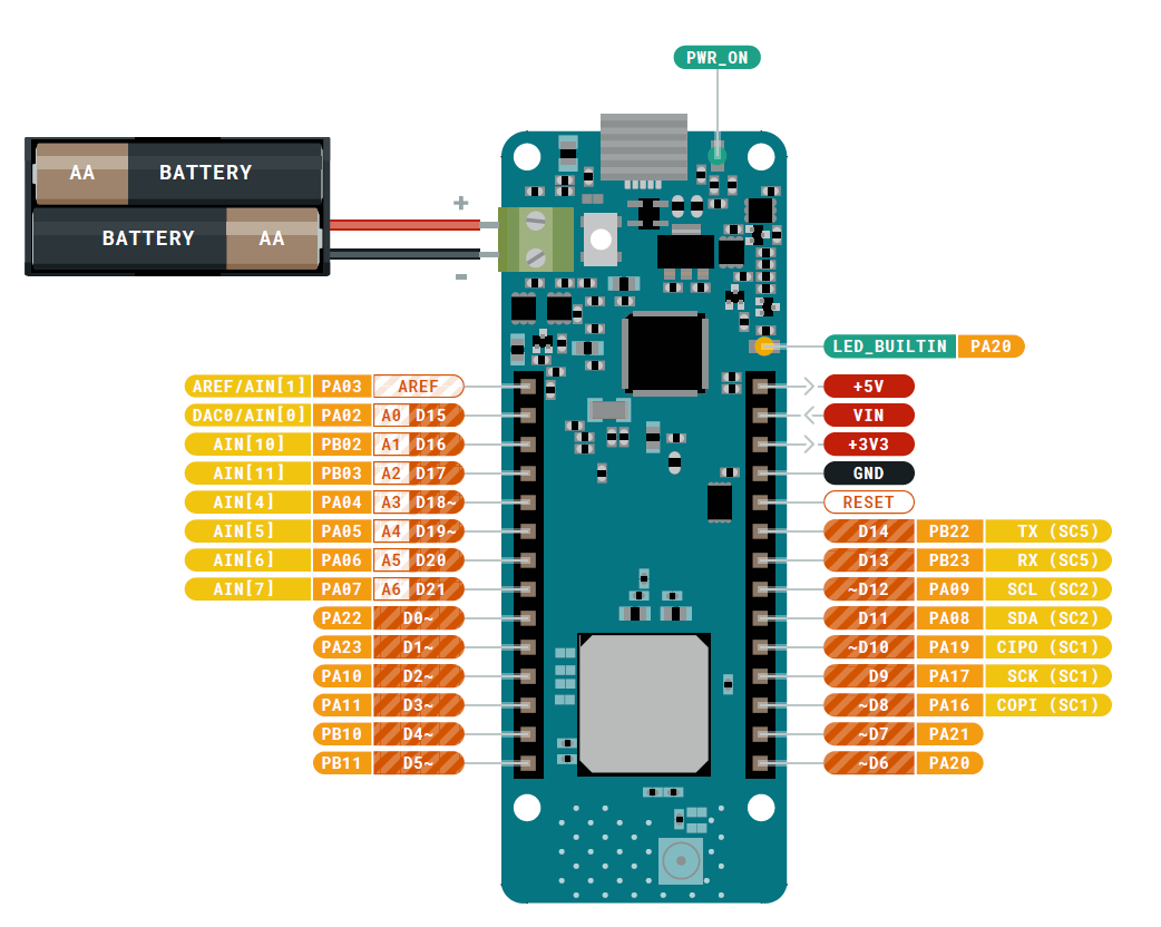
Pinout:
![]()
Pin Description:
- Analog Pins: There are 7 analog pins available on the board. These pins can get any number of values.
- Digital Pins: Total 8 digital pins are installed on the board which you can use either as an input or output based on the requirement. These pins offer only two states HIGH or LOW.
- PWM Pins: The number of pins that can be used as PWM pins is 12. These pins generate analog results with digital means when PWM pins are activated.
- UART Pins: The board contains two pins Rx and Tx for the serial UART communication. The Rx line is used to receive the serial data and the Tx pin is used to transfer the serial data.
- SPI Pins: This device also offers an SPI communication protocol that is mainly used to develop communication between the microcontroller and other peripheral devices like sensors. Two pins: MISO (Master Input Slave Output) and MOSI (Master Output Slave Input) are employed for SPI communication between devices. These pins are used to send or receive data by the controller.
- 12C Pins: The WAN board comes with a two-wire communication protocol known as the I2C protocol. This features two pins SDL and SCL. The SDL is a serial data line that carries the data while SCL is a serial clock line that is mainly employed for the synchronization of all data transfer through the I2C bus.
PROGRAMMING:
This board is programmed using Arduino IDE software which is an official software to program all Arduino boards: https://www.arduino.cc/en/software
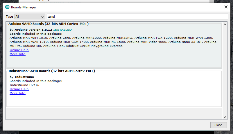
If you want to program your MKR WAN 1300 you need to add the Atmel SAMD Core to it. This procedure is done selecting Tools menu, then Boards and last Boards Manager as shown below.
![]()
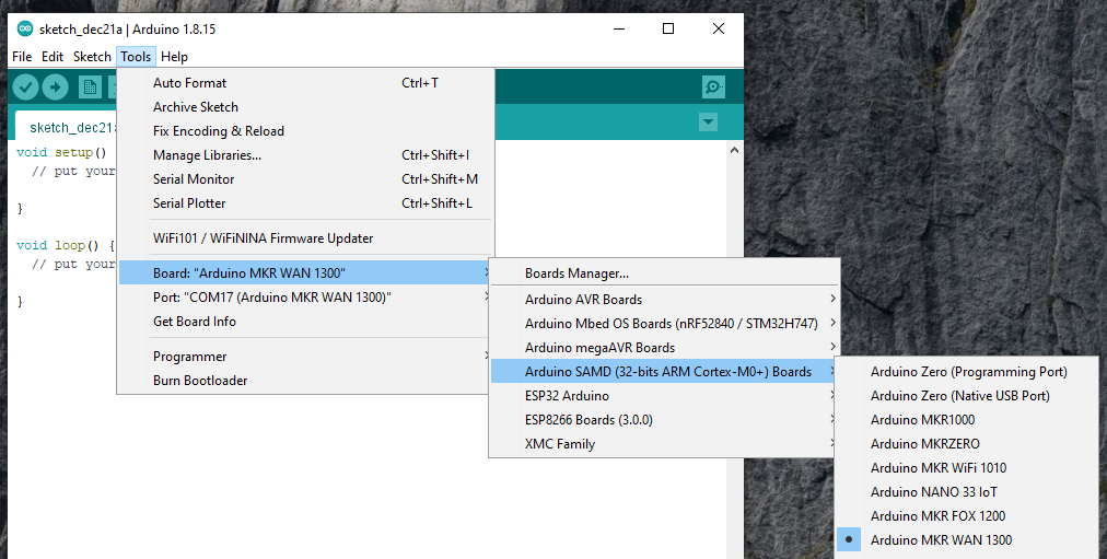
Now that the SAMD Core is installed, you can connect the board to the computer using a standard USB cable. Select your board type and port From Tools select the Board Arduino MKR WAN 1300. From Tools select the Board Arduino MKR WAN 1300.
![]()
Check the serial communication port.
![]()
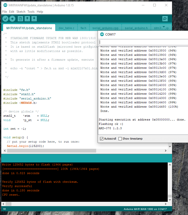
Now before you get started you will have to update the latest firmware on the MKR 1300 using the MKRWANFWUpdate_standalone sketch here: https://github.com/arduino-libraries/MKRWAN/tree/master/examples/MKRWANFWUpdate_standalone
![]()
After these steps, you are ready to start programming your MKR WAN 1300 board. For example you can try the blink sketch.
![]()
Environmental Toolkit for an Ecological Area
LoRaWAN IoT system with the Arduino MKR WAN 1300, that help my community to monitor the air quality and water of our ecological area